I can see a lot of traffic on the topic of tachometer accuracy. I studied the tach, with it's air core style meter, and came up with an idea. Why not design a replacement PC board that will work for all of the combinations? L4 1 coil and 2 coil, V6 1 coil and 3 coil, and V8 1 coil and 4 coil. One would just select the scale on a dip switch, replace the old PC board, and it would be right. The GT tach is rotated, and so may need a different PC board. It also might have a slightly different angle, as it goes to 6500RPM. But I need to confirm some math on this.. STOP me if I have it wrong, please.. L4 1 coil, fires twice per rev, 1800RPM at 60Hz, or at 6000 rpm, 200Hz. L4 2 coil, sensing one fire per rev, 3600RPM at 60Hz, or at 6000 rpm, 100Hz. V6 1 coil, fires thrice per rev, 1200RPM at 60Hz, or at 6000 rpm, 300Hz. V6 3 coil, sensing one fire per rev, 3600RPM at 60Hz, or at 6000 rpm, 100Hz. V8 1 coil, fires 4x per rev, 900RPM at 60Hz, or at 6000 rpm, 400Hz. V8 2 coil, sensing one fire per rev, 3600RPM at 60Hz, or at 6000 rpm, 100Hz. Were all Fiero tachometers scaled for 6000 RPM max? One detail would be making the non-GT board fit for the battery gauge or oil pressure gauge. Were there 2 oil pressure scales? And a big perk.. it could be made to capture peak RPMs, and you add external buttons to set/clear on the dash. I value any thoughts pro or con..
Originally posted by Chris Eddy: I can see a lot of traffic on the topic of tachometer accuracy. I studied the tach, with it's air core style meter, and came up with an idea. Why not design a replacement PC board that will work for all of the combinations? L4 1 coil and 2 coil, V6 1 coil and 3 coil, and V8 1 coil and 4 coil. One would just select the scale on a dip switch, replace the old PC board, and it would be right. The GT tach is rotated, and so may need a different PC board. It also might have a slightly different angle, as it goes to 6500RPM. But I need to confirm some math on this.. STOP me if I have it wrong, please.. L4 1 coil, fires twice per rev, 1800RPM at 60Hz, or at 6000 rpm, 200Hz. L4 2 coil, sensing one fire per rev, 3600RPM at 60Hz, or at 6000 rpm, 100Hz. V6 1 coil, fires thrice per rev, 1200RPM at 60Hz, or at 6000 rpm, 300Hz. V6 3 coil, sensing one fire per rev, 3600RPM at 60Hz, or at 6000 rpm, 100Hz. V8 1 coil, fires 4x per rev, 900RPM at 60Hz, or at 6000 rpm, 400Hz. V8 2 coil, sensing one fire per rev, 3600RPM at 60Hz, or at 6000 rpm, 100Hz. Were all Fiero tachometers scaled for 6000 RPM max? One detail would be making the non-GT board fit for the battery gauge or oil pressure gauge. Were there 2 oil pressure scales? And a big perk.. it could be made to capture peak RPMs, and you add external buttons to set/clear on the dash. I value any thoughts pro or con..
Wrong on most parts... I just put 86 4 cyl tach "made for" HEI engine as you think above on an 87 DIS Duke and tach does not care. (87 tach is bad and orange paint has faded and look close to yellow.)
1. OE and Aftermarket Tach's does not know or care what Ignition is used by the engine. DIS and HEI ignition modules have same tach output and hinds # of coils. Does need to know how many Cyl to report RPM. 4 cyl engine, whatever tach used and ecm gets 4 pulses per rev. 6 cyl engine tach/ecm sees 6 pulses per rev. and so on.
2. 4 and 6 cyl Tach electronics for Fiero (and many others) are the same but 4 cyl cars have oil pressure on same board. Get power and ground but otherwise have nothing to do w/ each other. 4, 6, and 8 cyl Tach does have same wiring but changes a few parts. A. Changes RC values for X pin(s) on the driver chip for total rage for needle swing. Example: V6 is ~270° but L4 is ~240° needle swing B. Changes RC values for Y pin(s) on the driver chip for Frequency base on # 1.
------------------ Dr. Ian Malcolm: Yeah, but your scientists were so preoccupied with whether or not they could, they didn't stop to think if they should. (Jurassic Park)
I respect the Mighty Ogre, but are you certain? I refer to these links.. https://www.fiero.nl/forum/A...031229-2-037230.html and http://www.fieros.de/en/articles/tach.html Let's take the single example of the 4 cylinder. If you have one coil (distributor), it fires twice per revolution. If you have DIS, there are two coils, and we only pick up one of them. There are two firings per revolution, but with 2 separate coils. Thus, we get only 1 pulse per revolution. Is this right so far?
Most GM tach reading high because the Capacitor in A. or B. above is bad. B. Cap Values see www.fiero.nl/forum/Archives...37230.html#p5 Many fix the resistor but is wrong part when you have bad tach. A new cap likely won't be exact so likely need a new trimmer resistor too. Cap's made in the same batch at the factory can vary a little and why GM used "laser cut" resister to fine tune the timing of RC set. You can replace a bad cap w/o resistor and see if close enough to work for most uses.
Note: B. cap could be fine and A. cap is making the chip to think needle range is bigger. IOW Tach in accurate but needle now moves to new total range. Was ~240° for 4cyl but now the chip thinks is 250° or more because of the bad cap in A. RC set
Oliver and others changes Resistor to convert for V8 mainly because Easy and Cheap to get them. Can work because Timing is done by RC and changing either part will change timing/frequency. And again, Even if Oliver used a cap... cap's can vary a little to a lot depending on type etc so might still need a resistor too to dial in the pointer for many conversions.
I can likely fix my 87 tach but gauge face is faded and I had a good 86 in spare parts. So I don't know exactly what part is bad or just even a crack in a solder joint is a problem.
[This message has been edited by theogre (edited 07-02-2016).]
I get all that, all true. But all of the Rs and Cs are converting a pulse waveform into a voltage, and the voltage drives the chip that moves the meter. I am planning to take the pulse waveform directly, without any F to V conversion, and drive the meter directly. So what I am trying to establish is the actual pulse frequencies for each engine/distrib setup, and just go past all of that analog stuff. And on your meter movement, there is a common post and two coil connections. You should read somewhere between 200 and 240 ohms from common to each coil, or 400-480 ohms across both coils. And the common is not the center post, it is one of the other two.
Unless you made a DIS module... You cannot see # of coils. Not even the ECM/PCM can see # of coils used. 4cyl using 1, 2 or 4 coils always behave as only 1 coil to the tach and ECM. (HEI And DIS of any type, ECMs often have different timing maps but doesn't matter for the topic.)
Car w/o Mechanical Distributor just move the function to primary and low volt side of system. You have a solid state distributor but just can't see it, even in many SM. Any and All coil switching is in the PIM/ICM and ECM and Tach doesn't know.
Again tach and ECM ignition reference signals are 1 pulse per spark plug firing. 4 cyl engine, whatever tach used and ecm gets 4 pulses per rev. Shape of signal pulse does not matter because signal goes thru buffers/filters to make signal good for whatever use.
Is Why you can use same Fiero OE Tach's regardless HEI or DIS as I said above and people w/ DIS v6 uses same Fiero V6 tach. All ECM and PCM does simple math for 4, 6, 8, etc, pulses on reference line per rev to calculate RPM for data stream. All OE and Aftermarket Digital Tach's work off the same signal and same tricks to get RPM.
[This message has been edited by theogre (edited 07-03-2016).]
I used to go to Advanced Circuits in Colorado, but I get them from China now. The schematic is done, the PC board is halfway done. My tach has been intermittent, and alas, I noticed yesterday that when I rap on the instrument housing, it makes/breaks the fault! Hopefully the new board solves that. Anybody out there have a GT style that they can loan me? Not working is fine.. the GT tach was at a different angle, and I have to work out the differences.
The PC board was ordered yesterday, looking at about 10 days to get it. Did I mention that it will incorporate a tach memory? Also, still looking for the GT style tach module, can be broken, just to use as a model and return. Anyone?
1. OE and Aftermarket Tach's does not know or care what Ignition is used by the engine. DIS and HEI ignition modules have same tach output and hinds # of coils. Does need to know how many Cyl to report RPM. 4 cyl engine, whatever tach used and ecm gets 4 pulses per rev. 6 cyl engine tach/ecm sees 6 pulses per rev. and so on.
I disagree with you on this...
With any 4 stroke engine the number of pulses per revolution will be half the number of cylinders regardless of the type of ignition.
4 cyl = 2 6 cyl = 3 8 cyl = 4
A 60 hz signal is equal to 3600 pulses per minute and a
4cyl = 1,800 6cyl = 1,200 8cyl = 900
[This message has been edited by jscott1 (edited 07-24-2016).]
Great minds think alike, I think that we agree. If you look at the OP, your 1800, 1200, and 900 are in there.. to the right of each engine with 1 coil. Since then I discovered that the 2.5 DIS that I have puts out a pulse stream of 2 pulses per revolution. Even though the schematic shows that the tach signal is plucked off of one coil, that is not reality. There is a pulse for both coils, so my DIS has the same pulse rate as a single coil (distributor) duke. The pulse is 5V and comes from the ignition module. And yes, I will market it to (us) through the forum. I am not sure that it merits going to Rodney or Fiero Store (or if they would even want to), so probably can fill the few interested parties direct. Gotta make it work first.. then make sure I can do the 3 variations so far. 1 Non-GT with oil pressure 2 Non-GT with battery 3 GT with ?? If anyone knows of more variations or has more data on ignition systems, please do tell. For instance, what are folks using on the 3800's?
Originally posted by jscott1: I disagree with you on this...
With any 4 stroke engine the number of pulses per revolution will be half the number of cylinders regardless of the type of ignition. 4 cyl = 2 6 cyl = 3 8 cyl = 4
Correct. Was Wrong on Pulse per Rev (can't sleep many days) but The rest Stands. Tach and ECM/PCM do not know any diff how many coils in the ignition. Already said above You can use any 4cyl tach and doesn't care or know the engine is HEI or DIS.
Can matter how you program Ignition Maps... HEI and others always have mechanical Base Timing that set at the distributor and ECM data counts for base timing. DIS w/ ECM control likely doesn't have base timing and timing calculated from TDC.
quote
Originally posted by Chris Eddy: Gotta make it work first.. then make sure I can do the 3 variations so far. 1 Non-GT with oil pressure 2 Non-GT with battery 3 GT with ?? If anyone knows of more variations or has more data on ignition systems, please do tell. For instance, what are folks using on the 3800's?
Just put 4/6/8 cyl switch/jumper on all of them. Otherwise you have same problem as OE one if/when they change engine later. 1. is used on 85-88 4cyl. 85 6cyl and maybe others w/o Rally Gauges but w/ v6 calibration and maybe different markings. (Have to set 6 cyl but can use same tach face.) 2. should skip for now. only used on 84. 3. "GT" w/ Rally Gauges are just a tach because oil and volt gauges over the radio. I'm guessing the the dash and "wires" on the back are the same. GT tack board just ignores oil sender. (Guessing but Knowing how GM made most parts to be the same.)
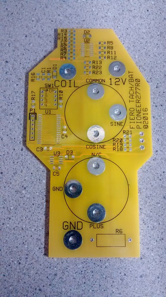
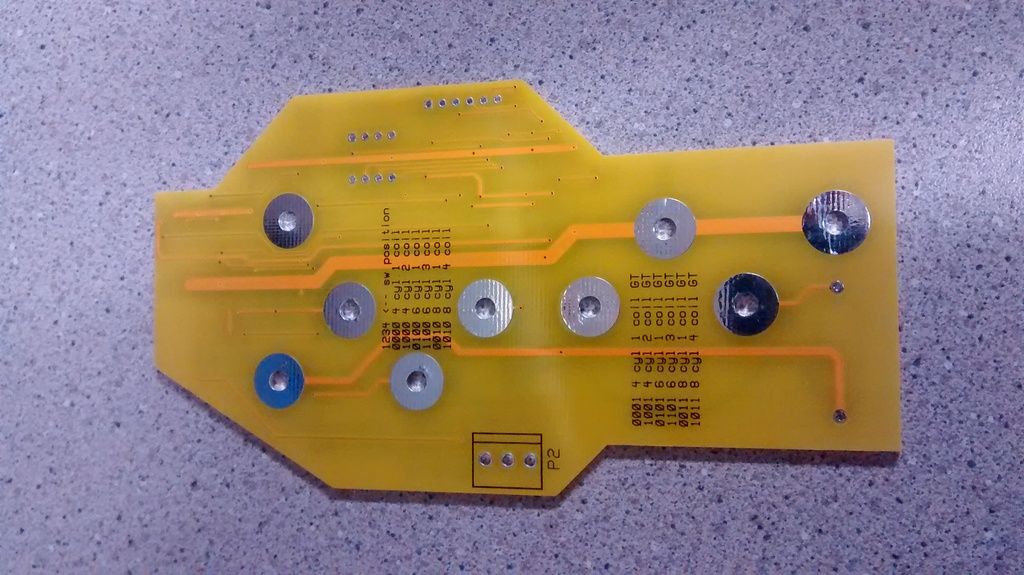
I did get the bare PC boards for the tach.. Notice the 3 pin connector on the back of the board. This is where one would wire in a button for tach memory recall. This one is the less common one with battery below. I have to take my own '87 apart to see what the differences are for the oil pressure version. I also do not have a physical example of a GT tach.. anyone want to loan out a broken one?? Just the tach module or tach PC board. I will start putting parts on it this week..
Ahoy.. Are you in the states? Patrick sent some photos, which helped with tying down the 3 variations. To do the oil pressure version, I only need to measure the exact position of the "sender" stud. Is this something that you can mail, or measure and report on? Thanks!
Ahoy.. Are you in the states? Patrick sent some photos, which helped with tying down the 3 variations. To do the oil pressure version, I only need to measure the exact position of the "sender" stud. Is this something that you can mail, or measure and report on? Thanks!
That's perfect.. just what I was looking for. I put the extra post on the revised PC board. I also have the software working somewhat now. I can make the needle go from 0 RPM to 6K, sweeping back and forth as a demo. When I get it smooth (it is jerky from floating point calculations) I will post a video.
Originally posted by Chris Eddy: That's perfect.. just what I was looking for. I put the extra post on the revised PC board. I also have the software working somewhat now. I can make the needle go from 0 RPM to 6K, sweeping back and forth as a demo. When I get it smooth (it is jerky from floating point calculations) I will post a video.
If chip will limit FP math to X points, y.xx not y.xxxxxxx, can help speed the math. If can limit # of samples/frames per second should help too. Above 24-30 fps, eye can't really see any more but adds a lot of math to process. You could likely use 15-20 FPS, maybe less, and see no different to your eye.
Part of Caps and RC net's in OE tach is to smooth out the needle movement. Could be need a change in meter output code or hardware to do the same.
If you test in the car... Iffy HEI tack filter can cause problems.
Agreed, the tach meter movement requires two voltages and a common.. one is the sin of the angle, and the other is the cos. I am considering just making a table of 250 integer value pairs (there are 250 degrees in the movement), and not doing any floating point calculations at all. With the tach filter, which affects only the 6 cylinder, I plan on performing basic debouncing of tach pulses input. Even if the pulses are dirty and bouncy, the software will hopefully sort through it.
Status update.. I have the processor controlling the tach needle movement. It just does a demo where it runs from 0RPM to 6KRPM and back again over and over. I would have included the video of it working, but I aint shmart enough to make photobucket work. Next, I read and scale tach pulse inputs, and scale them for 4/6/8.
Originally posted by Chris Eddy: With the tach filter, which affects only the 6 cylinder, I plan on performing basic debouncing of tach pulses input. Even if the pulses are dirty and bouncy, the software will hopefully sort through it.
Nope. Most HEI w/ OE Tach has the filter, including 84-86 L4 Fiero. Tach go to the Ignition Coil on HEI and many others and likely have a very noisy feed w/o the filter. Likely the filter helps stop Ignition noise to other circuits too because Tach wire connected to Ignition Coil can/will act as an antenna and broadcasts noise etc w/o a filter.
DIS engines Don't have the filter and Tach connect directly to the ICM. Tach pin is wires before coil drivers so can't get coil noise.
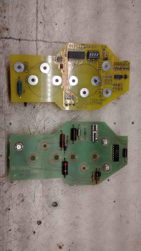
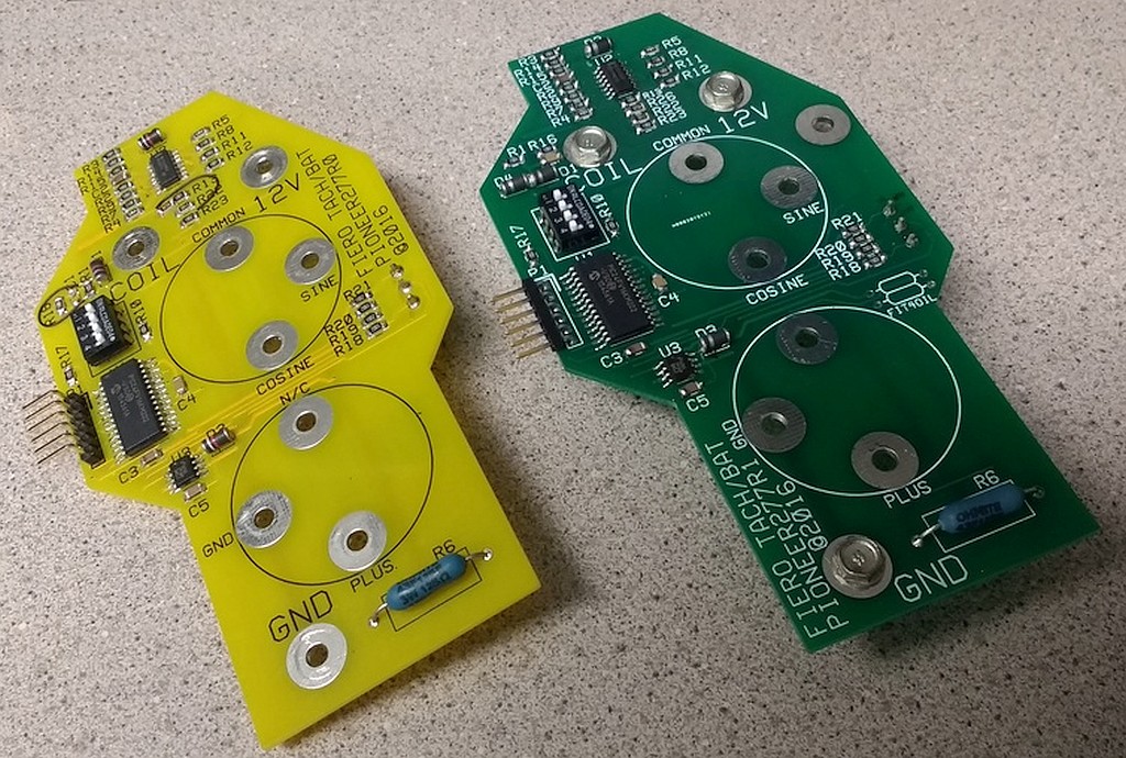
Ahoy, I have some progress to report on the universal tach. The old one is yellow, the new one is green.. The circuit where the tach pulses go in did not work on the older one, the new one has a new approach. Hope to put it on the car this weekend, and see if I can read tach pulses.