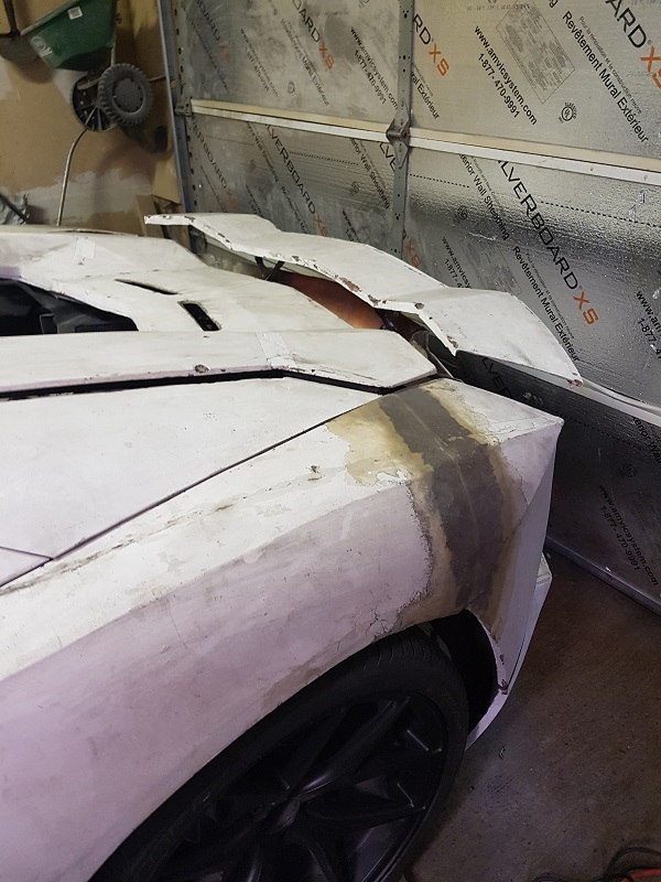
I completed welding the spoiler frame. I've also welded threaded inserts into the spoiler frame to ensure I have solid mounting points for the hinges. The hard part will be lining up the spoiler frame & hinges and then creating the required mounting points on the car's frame.
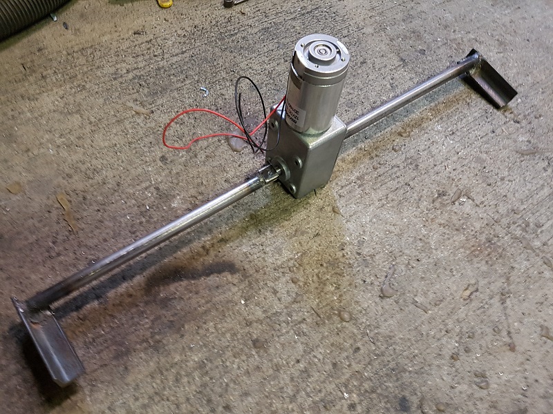
Started to put together the drive mechanism for the spoiler. It will be using a high torque, low speed geared motor. Of course I also discovered that the current framing for the bumper will be completely in the way of the drive mechanism...so, of course I'll have to make some changes to the framing. In the pics below, the spoiler framing is actually sitting about an inch and half lower than it should be. I'll set it up so that the mounting points are adjustable to allow me to easily adjust the lowest height and angle of the spoiler.
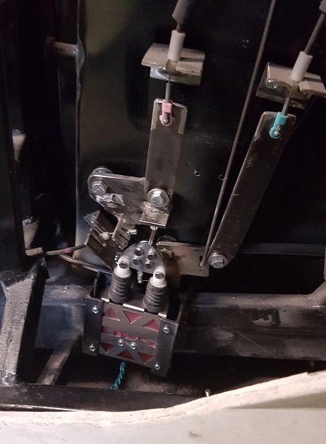
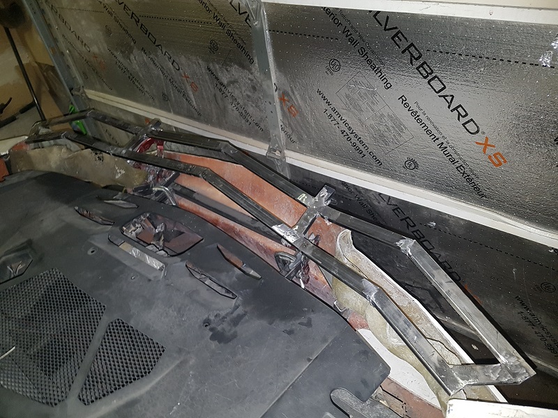
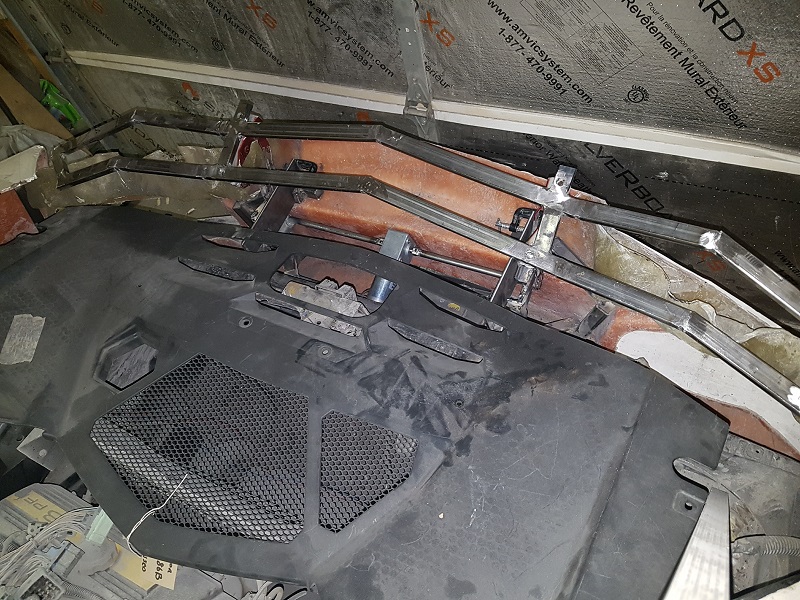
I've removed the framing that was interfering with the spoiler mechanism (also has the added bonus of getting it out of the way for the license plate lights). I'm now starting to install a couple of plates that will replace the removed framing and provide a surface for the hinges to be mounted. This gives me the ability to adjust the height and angle of the hinges easily. Lastly, once the hinges are bolted in place, I'll need to build a support bracket for the motor.
One thing I haven't touched on yet are the angle sensor, the limit switches and the motor controller that will be required. At some point I'll have to put all that together.
I took a few minutes to weld the adjustment plates into place for the spoiler hinges (plates can be seen in the previous pic). I can now properly align and clamp the spoiler hinges in place (to the plates)....giving me the ability to fine tune the adjustment. Almost. Before I align anything, I need to put together a bracket to mount the motor to the frame otherwise it will be the only thing spinning when I put power to it... Of course it will need to be adjustable too since it is rigidly mounted to the spoiler hinges.
It seems to me that an end-of-shaft magnetic angle sensor would be perfectly suited to this application:
A Melexis MLX91204 PCB-mounted 2D Hall sensor would give a sine/cosine output with angle. If you need a microcontroller to control the electric motor, it could be mounted on the same circuit board; all electronics in a single module. Might not need limit switches if you can teach the required target angles.
I would use a NdFeB diametrically magnetized magnet, with dimensions on the order of: 1/2" dia 1/4" thickness
Space it at least 1/8" from the angle iron, to avoid shunting the magnetic signal away from the sensor.
Thanks for the info! That is very similar to what I had in mind. I mentioned limit switches, but that was only since I was considering backup safeguards to be used to ensure power would be shut off to the motor should the angle sensor fail for some reason. Realistically, the spoiler isn't going anywhere since it mechanically stops at the two limits, but I hate the thought of driving more current into a stalled motor. The controller will be an Arduino with a motor driver shield, so likely will keep the sensor(s) independently mounted. The hall effect sensor is obviously a nicer solution than a simple resistive rotary sensor (i.e potentiometer). I've used them before in other projects.
Maybe a timeout would do it; if you don't get to the desired position within 10 seconds, the show stops.
Do you think the motor will need to be powered on to keep the wing up (due to aerodynamic downforce), or does the motor have too much drag to be backdriven?
In the fully up position, the turquoise and brown links (if you extend them) pass nearly through the rotation axis of the purple link. This means that the downforce won't have much tendency to force the wing down.
In the intermediate position, there is less angle of attack, so less downforce, but the linkage is less like a "locked knee", so this is probably the worst case in terms of torque required to hold the wing up.
I specifically selected a wormgear gearbox so that I wouldn't have to worry about that. It stays locked in whatever position it is in. I can definitely incorporate a timeout function in the code...obviously much simpler than bothering with the limit switch.
Time for a little update. I've slowed down significantly due to my ongoing health issues., but I'm still getting there slowly...
I did hit a big problem with the spoiler drive system and as a result I've modified my design slightly. While playing around with the spoiler drive mechanism I ended up damaging the motor gearbox. I didn't have the spoiler drive system clamped in place properly while I attempted to test run it. This resulted in something jamming on one side and with the amount of torque available from the motor something had to give... It ended up causing the output shaft to "slip" in the final gear. The shaft is now slightly loose in the gear and can actually be turned almost a quarter turn with the motor stationary. This is essentially useless now. I've shelved the motor for now and switched my design over to a using a linear actuator. The rest of the design remains the same, I'm just changing the method of generating the input torque. I'll try to get the new setup up and running over the next few days. (Things will be on hold for a week or so starting next Friday since I'm getting a little Lasik... )
If you're going to be re-doing this, I recommend to put the crankarm for the linear actuator adjacent to one on the hinges, not in the center. Having the crankarm in the middle of the shaft (and thus pushing on the middle of the shaft) will cause the shaft to bend like a banana.
Is this linear actuator also self-locking?
Does your software only do kinematics, or can it calculate forces as well (assuming a certain weight of the spoiler)?
With a crankarm, the linear actuator doesn't have a constant ratio; it is most effective when the actuator is perpendicular to the crankarm. So you may want to plot the required hold-up torque as a function of shaft angle, and then align the peak of the crankarm ratio with the "worst-case torque" angle.
Yes it is self locking and yes the crankarm is being positioned next to one of the hinges for exactly that reason (plus it keeps the linear actuator a little further away from the exhaust as an added bonus). I also switched from a hollow shaft to a solid shaft to additionally compensate for this. That particular software just does quick kinematics, though I'd design it in Solidworks and run it through Ansys if I was really worried about the specific torque-to-angle issues. I actually over designed it to begin with, so there shouldn't be any issues with this new configuration. The crankarm only has to rotate through 90 degrees, so this allows it to be positioned to minimize losses. Having said that, sadly the downforce on the spoiler isn't as much as many people would believe. They are more for show than function.
I would have preferred to keep my original setup...but I don't feel like buying another motor. Gear-motors with that amount of torque aren't cheap, and the warranty has expired on the one I had. Fortunately I have lots of linear actuators (of various specs) sitting on the shelf. Remember...design work is easy...manufacturing is always a little tougher. Sometimes one has to make compromises based on the parts and tools available. (Once the car is finished I'm putting together a CNC plasma cutter which will help a lot for future projects....just don't have the room right now).
Thanks for the info! That is very similar to what I had in mind. I mentioned limit switches, but that was only since I was considering backup safeguards to be used to ensure power would be shut off to the motor should the angle sensor fail for some reason. Realistically, the spoiler isn't going anywhere since it mechanically stops at the two limits, but I hate the thought of driving more current into a stalled motor. The controller will be an Arduino with a motor driver shield, so likely will keep the sensor(s) independently mounted. The hall effect sensor is obviously a nicer solution than a simple resistive rotary sensor (i.e potentiometer). I've used them before in other projects.
Rather than limit switches for end of travel, use load sensing to shut off power to the motor when a load spike from a stalled motor is detected. The benefit to this is that it will detect a stalled motor at any point in its travel. So if something happens to get caught in the mechanism - twig, stone, fingers, etc - it will stop the motor.
I personally have issues with sensors - especially mechanical sensors - in an automotive environment. Too many opportunities for failure due to environmental impact on the sensors. Hall-effect sensors are better as there's no moving parts, but their impact on the mechanism occurs, by design, at a single point, whereas triggering off the current load occurs at any point in the mechanism's travel.
In addition, swap out the motor for a stepper motor, and you can have a system that can "learn" where its limits are (with proper programming) and from that point on, will only drive excess current to the motor when something blocks the mechanism. You can also use the properties of the stepper motor to drive your mechanism to specif angles.
Welcome to PFF!
Since I've switched over to a linear actuator, this has actually eliminated a number of the issues that I faced by using the gearmotor. Limit switches are built in, and through design, it'll open and close to the full extremes without needing to worry about external sensors to stop it. It does need a sensor to indicate when it reaches the intermediate setting (only because I didn't happen to have a linear actuator with built in potentiometer), but everything else is built in already. Using a load sensor is a good idea (especially if you fear the failure of the mechanical limit switches), and I may incorporate it at some point since it is actually relatively easy to incorporate with my control system.
Using a stepper motor is more complex...and wouldn't help eliminate the requirement for position sensors. While you can use the count to indicate position, if the spoiler were ever held up in one spot, then the count is meaningless. There are ways around that, such as resetting to a bump-stop, or having at least one limit switch to indicate a defined position. The added control system is quite a bit more complex.
Well, that's what I get for trying to hold/follow two similar conversations at once - this one, and one on arduino control of a power window system. I knew you'd switched to a linear actuator, and replied with the idea of using a load sensor, but somehow mixed in some of the power window system ideas as well...really need to focus on one thing at a time
Personally, I think the biggest benefit to load sensing is safety. Limit switches are fine for either end of the mechanism's travel, but have no way of detecting when the mechanism is unexpectedly blocked. A load sensor will detect that. Potentially protecting your motor or mechanism from damage. Or more importantly, poorly positioned fleshy bits.
I agree. Load (current) sensors are a definite safety asset but are often overlooked. They can make a control system seem like it's more complex to put together...yet in reality they don't take a lot of effort to include. I use Arduinos for controllers since this is what they excel at. A simple amount of code, and an endless array of digital and analog sensor inputs, plus multiple digital, analog and pwm outputs. Limit switches are valuable for defined positional cutoffs, stopping the need for the motor to hit a hard stop to raise the load sensor enough to trigger a stop.
Finally got into the garage for an hour today. Not much, but didn't want to over do things having just gotten the eyes done.
Having said that, I really didn't actually achieve anything. The plan was to cut and shorten one of the links on the spoiler hinges to improve the angle at the top setting. Unfortunately, even after shortening the maximum I could, I'm still not happy with the angle that the spoiler achieves in it's final position. Installed, it just looks like it's coming up too flat. The spoiler is supposed to go to 4 degrees and 11 degrees for the two settings. It does that, but that's assuming that the lowest setting is considered 0 degrees, and the given specs use the down position as the reference...at least that was my understanding. It's lowest setting really isn't documented anywhere (that I've found), and I had just assumed that without actually thinking about it. I suspect it's lowest setting should be a negative angle giving much more than 11 degrees of total rotation. I'll have to reassess the hinges and see if I can modify them to give a more aesthetically pleasing final angle position (ummm...plus awesome downforce from great engineering calculations...)
So....summary....I spent an hour cutting two links, re-welding them back together and essentially getting no significant change. Welcome back to the garage.
Perhaps you can take some "artistic license" with the spoiler angle, and do what you find is pleasing to the eye. I would consider this approach.
I would think that the parked position is unspecified, and that 4° and 11° refer to the angle of attack; the angle of the chord line relative to the wind... or if not the wind, the horizontal (perhaps more likely).
Yes...I had a big discussion with the surgeon on this. I was a little worried about the welding fumes but he reassured me that a week was sufficient. I still need to ensure good ventilation, etc.
I'll definitely go with artistic feeling. I'm really just aiming for "close enough"....but it still needs to look "functional".
First pic more or less shows a comparison between oem and my setup. Too flat...but I'm running out of options to tweak the angle. Unfortunately, the link I need to shorten to correct this is already as short as I can make it without completely tearing the hinges apart and rebuilding them from scratch.
There are quite a few videos of the spoiler operating. The best one is this: https://www.youtube.com/watch?v=dVzWV_7586E since it shows the oem drive system being bench tested. If I decide to do a redesign, I'll probably duplicate this. The problem still comes down to creating pivot joints without slop. I could design and draft it up and have it manufactured at a machine shop, but that will be pricey. As mentioned before, I lack much of the machine shop equipment required to do it completely myself.
I finally got back to working on the door opening mechanism today. I replaced the annoyingly loud door release solenoid with an AVS dual-motor opener. Works perfectly...and definitely much quieter!
I was finally able to get rid on the last two remaining Fiero body panels that I sitting around (the two roof panels). I had them for sale...but after waiting two years I was happy to just them get rid of them (did get a nice bottle of wine out of it though, lol)
I received a nice shipment of exhaust parts from Summit Racing. So I figured this is as good a time as any to finish the exhaust.
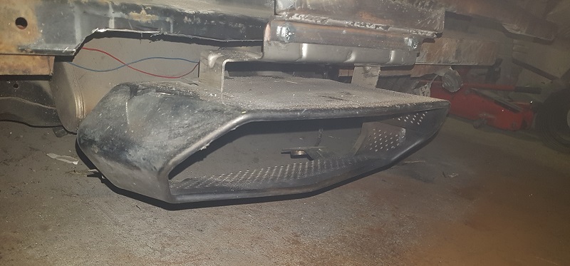
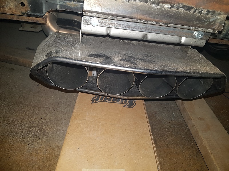
I started by adjusting the angle of the exhaust heat shield. The outlet seemed to be pointing down a little. After some tweeking (as opposed to some twerking... ) the exhaust shield angle is much more pleasing. (Picture shows exhaust shield with bumper moulding removed.)
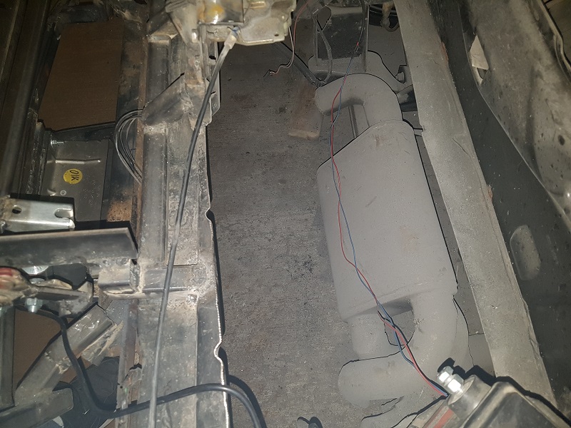
The muffler (Jones Full Boar, Quiet Tone) has a single 2.5" inlet and dual 2.5" outlets. It sits in the stock position. Of course the trunk has been completely removed since it no longer has any function.
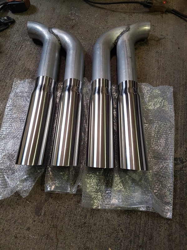
Now for the most important part...3" stainless steel exhaust tips. I've created a couple of single inlet, dual outlet pipes. The tips slip over top of these pipes...so once the pipes are welded to the muffler outlets, I'll be able to accurately align the tips to the shield. (I'll remove any excess of the pipes before the tips are welded).
Thanks Bob! I'll save the twerking for the "after-build-completion" party.
Getting everything welded together is a little tough. I started by welding a small beam across the two splitter sections so that the four outlet pipes are properly aligned with respect to each other. Now I just need to weld a couple of 90 degree bends to connect the muffler to the pipes. I'm hoping to get the assembly welded into place tomorrow.
[This message has been edited by Neils88 (edited 05-27-2017).]
I was away this week for a nice visit with family. Back to work today. I shortened the pipes and added the curved sections to connect to the muffler. I still need to make the final welds to the muffler outlets, then I can do the final alignment of the 3" stainless exhaust tips. They have a fair bit of play where they connect to the 2.5" pipes so it should be relatively easy to get them properly aligned
I've finished most of the welding on the Exhaust. I'll still need to install some hangers to keep the exhaust in place. I will need to add a couple of flanges between the muffler and catalytic converter so I can more easily split the system. Then I'll be able to take the rear section off and complete the welds that I can't currently reach.
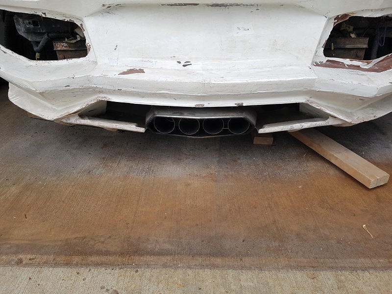
I'm not sure if I'm really happy with the exhaust though. If you crouch down behind the car, you can see into them fairly far and the inner pipes look a little awkward. Real Aventador exhaust pipes come directly off the muffler and are angled...you can't see more than about 6" into the tips, at which point they bend upwards. You can see about 16" into my pipes. I'll likely leave it for now, but if I obsess over it, then I'll have to change them again, lol. (Note, rear bumper moulding isn't fully aligned and installed in the pic below)
Maybe use some kind of fine screen a couple inches inside the end, possibly stainless to reduce being able to see into the tips. Might look like a spark arrestor but could be worth a try.
Maybe use some kind of fine screen a couple inches inside the end, possibly stainless to reduce being able to see into the tips. Might look like a spark arrestor but could be worth a try.
That's a good idea...but I think that may draw more attention to the issue (and I worry that I won't be able to make the mesh look good). If the carbon buildup doesn't mask it (the metal is really shiny inside the exhaust currently) then I may just adjust the pipe angle so that it becomes much harder to see into the exhaust. Mind you, even the pic I took had me almost lying on the ground, so I suspect no one else will notice this unless they are really inquisitive.
I would be tempted to try some high heat flat black BBQ paint and bake it on per can instructions. Just tossing up ideas. I'm about ready to figure out how to "hide" the fuel cap on my Countach with a vent type screen door. I'm just not good with it showing like the originals. Plus mine is on the driver side.
I would be tempted to try some high heat flat black BBQ paint and bake it on per can instructions. Just tossing up ideas. I'm about ready to figure out how to "hide" the fuel cap on my Countach with a vent type screen door. I'm just not good with it showing like the originals. Plus mine is on the driver side.
I think you're right about the BBQ paint. Flat black paint would definitely take away the reflection that makes it stand out more than I had anticipated.
I was going to keep my gas line on the driver's side as well, but I ended up biting the bullet and installed it on the passenger side, like the oem. Now I've got to reroute the fill line. What exactly are you trying to hide? I'm keeping the Fiero fuel cap, but of course it's hidden under an oem fuel door.
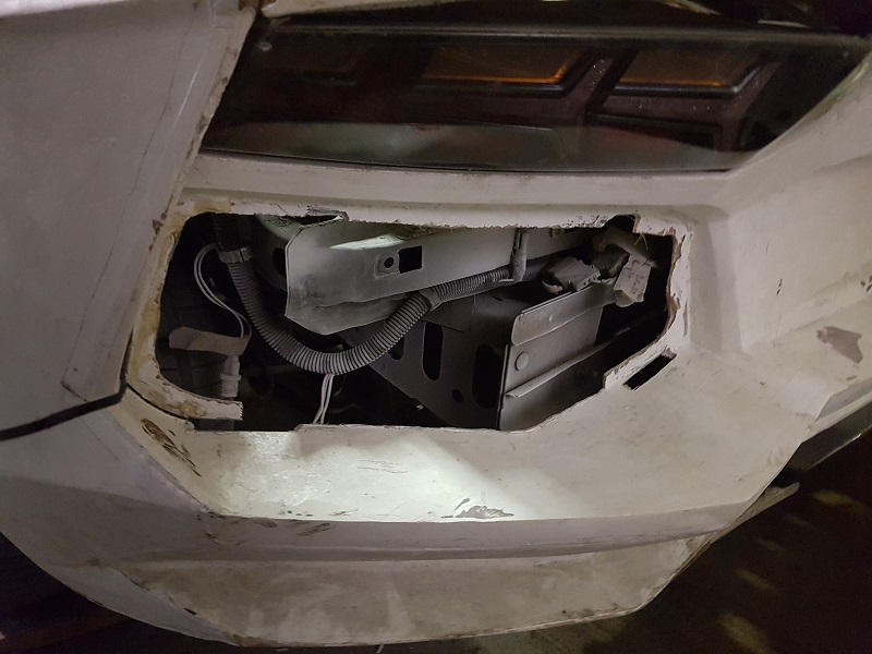
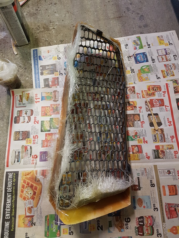
While I'm working on the rear end of the car, I figured I'd get the rear grills set up. This is the opening...
I'll likely be removing some of the interference items and will install dual intercoolers (one per side) for use at a later date. These will visually block the openings which would otherwise just look messy. (I think I discussed this earlier in the thread). There will be a decent amount of air flow through the upper side vents passing over the wheel wells and directed out through the grills. I'll just leave the intercoolers disconnected for now.
I'm using oem grills and decided to mould the trim pieces to hold them securely. The trim pieces will eventually be sanded and painted flat black, then I'll add some fasteners to allow me to bolt them in place.
...unfortunately I ran out of some supplies, so I wasn't able to get these finished.


 Of course it will need to be adjustable too since it is rigidly mounted to the spoiler hinges.


 The controller will be an Arduino with a motor driver shield, so likely will keep the sensor(s) independently mounted. The hall effect sensor is obviously a nicer solution than a simple resistive rotary sensor (i.e potentiometer). I've used them before in other projects.
 It ended up causing the output shaft to "slip" in the final gear. The shaft is now slightly loose in the gear and can actually be turned almost a quarter turn with the motor stationary. This is essentially useless now. I've shelved the motor for now and switched my design over to a using a linear actuator. The rest of the design remains the same, I'm just changing the method of generating the input torque. I'll try to get the new setup up and running over the next few days. (Things will be on hold for a week or so starting next Friday since I'm getting a little Lasik...
  )
)