And any suspension points I want (custom suspension)
ccfiero and coppertop have made some sweet knuckles with plate steel and a brake
I scoured the internet looking for others who have made knuckles from a plate steel and welded construction, I could only find some 4x4 knuckles made this way.
I believe the Slalom front suspension made by HELD has drop spindles made from plate steel and tubing.
I am just looking for advice or tips on constructing knuckles in this manner and am open to other ways of doing it as well.
Obviously one goal is too keep the knuckles lightweight, but at the same time I would not want knuckles to fail on me. I am planning on using FEA with the cad file I produce to determine whether it will be strong enough to withstand track abuse
I have substantial CAM and CNC milling experience as well so the possibility of milled aluminum knuckles came to mind, though I would most likely need to mill on a 5 axis machine and I have never done that before. There would also be higher material costs and I have seen that machined knuckles are not as strong as cast knuckles, though the source was referring to a specific application so I do not know if this is a general rule of thumb or just one instance.
Let me know your input, I am in the beginning stages of design so I am open to anything.
Machined vs cast depends greatly on material cast, and casting method used. I would imagine just about anything machined from a chunk of billet aluminum would be stronger than a cast aluminum counterpart.
------------------ "I am not what you so glibly call to be a civilized man. I have broken with society for reasons which I alone am able to appreciate. I am therefore not subject to it's stupid laws, and I ask you to never allude to them in my presence again."
Lots of OEM's cast knuckles in aluminum... you can compare older steel spindles to new aluminum knuckles to get a feel for where the casting has to be thicker to take the same loads.
I would suggest starting with 1/2" or thicker plate steel water jet cut into a shape that will accept the hub of your choice (mine would be C6 Corvette ZR1) and the brake calipers. Then drill holes to bolt on ball joint bosses. If you have access to CNC equipment, you could make your own bolt on ball joint bosses. I think most or all of the universal ball joint bosses sold by race car fabrication supply houses are intended to be welded on. There are also bolt on or weld on steering arms available from the street rod industry.
If you have the capability to move the bosses an steering arm around, then you can play with camber, caster, kingpin inclination and ackerman MUCH more easily than if you welded up one set of knuckles at a time.
Originally posted by zkhennings: Obviously one goal is too keep the knuckles lightweight, but at the same time I would not want knuckles to fail on me. I am planning on using FEA with the cad file I produce to determine whether it will be strong enough to withstand track abuse
I assume you have access to a decent FEA package through an institution of higher learning. If you spin this right, you can probably get class credit for it. I think back when I did an FEA project for class credit it was a driveshaft yoke, but that's going on 10 years ago now.
The real challenge with the analysis, as I see it, is getting some idea for what the design loads at the knuckles are. Any load values you put in will produce a pretty Blue-green-yellow-red topography, but it's really meaningless if it doesn't correlate to what's happening on the car.
Then again, that might get you some credit in another class, if you set up one of your current front knuckles with some strain gauges and calibrated them and then took some data on a skidpad, slamming sideways into a curb, and so on.
Perhaps you can ballpark something like.... Load in Z: MASS_vehicle x %weight_front x 3.5G x safety_factor (to simulate hitting a bumpstop in suspension compression, with one wheel carrying all frontend load) Load in Y: MASS_vehicle x %weight_front x 2x max_expected_cornering_G x safety_factor (to simulate peak instantaneous lateral load on the front) Load in X: MASS_vehicle x 1.2G x safety_factor (to simulate worst-case load on knuckle during max-effort braking with decent tires)
^Really just talking out my ass here, spitballing, I'm a powertrain engineer, so I don't look at the numbers involved at the wheel ends much, if at all.
Of course, you'd want the knuckle to be able to handle all the forces simultaneously for situations that happen at the track like running off-track in a corner, where you're some combination of piling on the brakes and/or turning at max ability to avoid going wide, and also crashing over the rumble curbs on the outside of the corner.
You also have to consider the fatigue properties of your choice of material, since it has to be able to endure some lower levels of these cyclic loads tens-to-hundreds of thousands of times in the part's life.
Perfect, thanks for all the responses. I looked up some rapid waterjet companies, has anyone used a company for waterjetting that they would recommend?
Kurt, thanks for the input on loading, unfortunately I graduated recently and my FEA access is through my work now, so no class credit for me.
Ultimately do you think plate steel knuckles would end up heavier than a machined aluminum knuckle of the same strength? Because I'm definitely trying to reduce unsprung weight by being able to use lighter calipers and don't want to totally negate that with heavy knuckles. I assume a steel construction would be heavier but roughly by what percentage?
[This message has been edited by zkhennings (edited 01-21-2015).]
Originally posted by zkhennings: Ultimately do you think plate steel knuckles would end up heavier than a machined aluminum knuckle of the same strength? Because I definitely trying to reduce unsprung weight by being able to use lighter calipers and don't want to totally negate that with heavy knuckles. I assume a steel construction would be heavier but roughly by what percentage?
30-40% heavier is generally what you're going to get with steel over aluminum.
I've been looking around for the possibility of using some knuckles from other cars on the Fiero, as well, but haven't found anything that will let me use the hubs I want. As a result, I've also been pondering with the idea of designing and machining some custom billet aluminum knuckles for the Fiero. The plan to design them is to design them in a way to accept a few different bolt-on hub types. When I get my mini mill set up, and converted to CNC, I should be able to make some easily enough, once I get the design done. As a first design, I'd probably make them to fit the stock 84-87 suspension, since I have an 87 GT, and am not necessarily trying to redesign the suspension yet. I just want the brake dimensions and design, and wheel sensors, off the Matrix/Vibe, to start with.
[This message has been edited by dobey (edited 01-21-2015).]
I have been looking into building a CNC and might do so in the near future, this would be a fun first project to run on the mill. Almost all of the CNCs I have seen for home use have no coolant setup, have you seen any that do? Seems to make endmills last a lot longer than just using compressed air.
I will most likely make knuckles in the near future with plate steel and I will make them customizable as Will was suggesting. Then I will know the ideal geometry and if I am unhappy with the unsprung weight I can machine them from aluminum.
[This message has been edited by zkhennings (edited 01-21-2015).]
I have been looking into building a CNC and might do so in the near future, this would be a fun first project to run on the mill. Almost all of the CNCs I have seen for home use have no coolant setup, have you seen any that do? Seems to make endmills last a lot longer than just using compressed air.
I will most likely make knuckles in the near future with plate steel and I will make them customizable as Will was suggesting. Then I will know the ideal geometry and if I am unhappy with the unsprung weight I can machine them from aluminum.
The customizable design lets you set the geometry where you want it. In addition to kingpin inclination, caster angle, etc. there are many things to tune. For example, Fiero steering is very slow. Shorter steering arms would speed the steering up. If you bolt on a shorter steering arm and find that the tires scrub in tight turns, you can then just shim the steering arm to get the ackerman right... If you'd machined the knuckle, you'd have to make another new part every time you wanted to change something.
What I'd *REALLY* like to play with is a low steering offset and shallow kingpin angle combined with a high caster angle to give caster induced camber gain to help with grip in tight corners. The larger caster angle would result in a large mechanical trail, high steering effort and poor steering feel. To negate these, cut a main plate with some forlauf (leading pin) geometry to reduce the mechanical trail.
If you're a smidge smart about the steel plate design and include shims under the ball joint bosses from the beginning, then you can simply ditch the shims and install water jet cut 5/8" or 3/4" aluminum plate in place of the 1/2" steel plate.
People over on Locostusa.com build spindle/knuckles for the locost cars quite often. Some even post plans. I have plans for a rear knuckle but I don't think I have anything for a front spindle. You might be better off finding a spindle from another car that meets your requirements and fabing new arms to that spindle. There are multiple suspension calculators for checking different spindle and pick up point combinations. The Locost guys usually use a program called "Wishbone" that is available for download. You plug in all your pivot points and dimensions and it outputs camber gain charts, roll centers, etc for differnet amounts of bound and rebound. All of this is extremely important to the design of suspension.
People over on Locostusa.com build spindle/knuckles for the locost cars quite often. Some even post plans. I have plans for a rear knuckle but I don't think I have anything for a front spindle. You might be better off finding a spindle from another car that meets your requirements and fabing new arms to that spindle. There are multiple suspension calculators for checking different spindle and pick up point combinations. The Locost guys usually use a program called "Wishbone" that is available for download. You plug in all your pivot points and dimensions and it outputs camber gain charts, roll centers, etc for differnet amounts of bound and rebound. All of this is extremely important to the design of suspension.
I have wishbone right from the locost site. I had not seen ones with custom knuckles however I will check them out
Originally posted by zkhennings: I have been looking into building a CNC and might do so in the near future, this would be a fun first project to run on the mill. Almost all of the CNCs I have seen for home use have no coolant setup, have you seen any that do? Seems to make endmills last a lot longer than just using compressed air.
I've seen various cooling set ups on the mini mills/lathes that have been converted to CNC. I'll probably build a fogger for mine. You don't really need coolant for aluminum and other softer metals though; only really for steel and harder metals. And I plan to hook up a small shop vac to pull the chips out of the way, and bucket them for recycling.
What I'd *REALLY* like to play with is a low steering offset and shallow kingpin angle combined with a high caster angle to give caster induced camber gain to help with grip in tight corners. The larger caster angle would result in a large mechanical trail, high steering effort and poor steering feel. To negate these, cut a main plate with some forlauf (leading pin) geometry to reduce the mechanical trail.
I have had very similar ideas to lower the offset (kingpin angle) and decrease steering arm length but I had not considered bumping the caster to gain camber. Would you then decrease camber gain from suspension compression to gain better straight line braking performance?
Also, I can see vorlauf geometry making for extremely fast steering but would the downside be crazy kickback on bumps around turns? In a straight line it would track very well and with a low offset not be disturbed by bumps very much, but when turning that must create a decent moment, how far back from the center of the wheel would the kingpin axis have to be moved?
At 8* of caster say and stock wheel tire diameter is 24.69"
Then (12.35)sin(8) = 1.719" as a rough mechanical trail length.
So would you figure if stock steering feel is fine at caster of 5* then
(12.35)sin(5) = 1.076" --> 1.719 - 1.076 = 0.643" of offset to lower steering effort to that of stock?
So I figure in a straight line this will behave similarly to 5* of caster, but around turns you get the camber gains of 8* of caster
I know the trail lengths are not exact since I used the adjacent length (tire radius) as the hypotenuse but close enough to get the idea
I've seen various cooling set ups on the mini mills/lathes that have been converted to CNC. I'll probably build a fogger for mine. You don't really need coolant for aluminum and other softer metals though; only really for steel and harder metals. And I plan to hook up a small shop vac to pull the chips out of the way, and bucket them for recycling.
Without coolant I have gotten tons of chatter in tight radius corners where there is a lot of flute engagement (milling around 1 inch deep into 6061) and I wrecked a few parts until I went with a machine with coolant, a HAAS minimill. It also helped to use a tool path in those tight corners that did not follow the wall profile until the finishing pass
Originally posted by zkhennings: Without coolant I have gotten tons of chatter in tight radius corners where there is a lot of flute engagement (milling around 1 inch deep into 6061) and I wrecked a few parts until I went with a machine with coolant, a HAAS minimill. It also helped to use a tool path in those tight corners that did not follow the wall profile until the finishing pass
You were taking a full inch deep of material out of a 6061 block at once? You should take lighter cuts.
The biggest problem with the cheap mini mills isn't the lack of coolant systems, but the fact that they are small and have less stability than larger and heavier mills do. If you get chatter on one, something is loose somewhere, you're hitting backlash, or taking too big a cut. Adding coolant probably wouldn't help. It might dampen the chatter noise, but it won't increase stability. Anyway, there's lots of videos on YouTube, and plenty of discussion on hobby machinist forums and such, if you want to learn more about CNC conversions for the cheap mini mills/lathes. We're starting to get a bit too off topic with it.
When I get my machines set up and CNCed though, I'll be making some parts for Fieros, for sure.
HAAS mini mill very expensive
and no I think it was doing 0.15" steps not an inch at once, but at those corners once you are in the final passes it chatters because it is close enough that the chatter at the bottom since the endmill has to have decent stick out, it causes it to chatter along the whole length.
Ive used manual lathes with no coolant on aluminum but cut depth is quite shallow
Regardless it's all moot because you wouldn't run into those conditions milling knuckles
[This message has been edited by zkhennings (edited 01-21-2015).]
I have had very similar ideas to lower the offset (kingpin angle) and decrease steering arm length but I had not considered bumping the caster to gain camber. Would you then decrease camber gain from suspension compression to gain better straight line braking performance?
Also, I can see vorlauf geometry making for extremely fast steering but would the downside be crazy kickback on bumps around turns? In a straight line it would track very well and with a low offset not be disturbed by bumps very much, but when turning that must create a decent moment, how far back from the center of the wheel would the kingpin axis have to be moved?
At 8* of caster say and stock wheel tire diameter is 24.69"
Then (12.35)sin(8) = 1.719" as a rough mechanical trail length.
So would you figure if stock steering feel is fine at caster of 5* then
(12.35)sin(5) = 1.076" --> 1.719 - 1.076 = 0.643" of offset to lower steering effort to that of stock?
So I figure in a straight line this will behave similarly to 5* of caster, but around turns you get the camber gains of 8* of caster
I know the trail lengths are not exact since I used the adjacent length (tire radius) as the hypotenuse but close enough to get the idea
Caster induced camber gain only occurs when caster is greater than kingpin inclination and is only effective when there is a large steering angle... it doesn't affect more or less straight line performance like braking.
Because the center of force of the contact patch still has a lever arm equal to the mechanical trail, this is what pavement forces use to work on the steering... so I don't think it gives more kickback on bumps. BMW uses vorlauf geometry on older M3's, which run more caster than normal 3 series cars.
When a tire is generating grip but not sliding, the center of force of the contact patch is behind the geometric center of the contact patch. When the tire starts to slide, the center of force of the contact moves forward to the geometric center. If the migration of the center of force is a large enough component of pure mechanical trail (30%? 50%?), then there will be a significant reduction of steering effort when the tire starts to slide. The overall result is good "contact patch feel" and steering feedback.
Caster induced camber gain only occurs when caster is greater than kingpin inclination and is only effective when there is a large steering angle... it doesn't affect more or less straight line performance like braking.
Yes what I meant was because you will gain more camber on turns, would you design the suspension to not gain as much camber on compression, and that would result in better braking since when the front end squats under braking the tire will remain perpendicular or close to it.
The caster induced camber gain happens in slow turns with high steering angle. Higher speed turns with less steering angle still need camber gain to keep the tire effective with body roll.
and no I think it was doing 0.15" steps not an inch at once, but at those corners once you are in the final passes it chatters because it is close enough that the chatter at the bottom since the endmill has to have decent stick out, it causes it to chatter along the whole length.
Why would you buy a new CNC for hobby jobs? I know of dozens of usable, full 3 axis CNC mills for sale for less than 25k. A good knee mill with 3 axis CNC control can do this no problem, and is a lot cheaper than an enclosed machining center.
Regarding the chatter in the corners, either slow down your federate on all G02/G03 internal arc commands, or put in a half second dwell command while in the corner, so the cutter doesn't cut on 2 sides at once. This will eliminate your chatter. Make sure you climb mill.
[This message has been edited by cam-a-lot (edited 01-23-2015).]
Why would you buy a new CNC for hobby jobs? I know of dozens of usable, full 3 axis CNC mills for sale for less than 25k. A good knee mill with 3 axis CNC control can do this no problem, and is a lot cheaper than an enclosed machining center.
Regarding the chatter in the corners, either slow down your federate on all G02/G03 internal arc commands, or put in a half second dwell command while in the corner, so the cutter doesn't cut on 2 sides at once. This will eliminate your chatter. Make sure you climb mill.
I was planning on DIY CNC router type deal for cheap like ~ $1000, the enclosed machine is the HAAS mini mill that I used a lot in college, not what I would be planning on buying. And yea we chose a profile that took out pockets at a time instead of following the wall profile.
And Will, I know you still need camber gain in normal cornering situations, but the additional caster angle would cause additional camber in higher speed turns, just not as much. I was just wondering if that gets taken into your considerations when designing the camber curve of the front suspension.
A custom made machined aluminum rear spindle would be something I would buy .Would make it much easier to do this : You could machine in a fork type mount on both sides for bolting in upper arms .Bolting arms to the strut stub is a bit of a pain .
I put the pivot where it is so the arm would follow the same basic motion as the strut .I did not want to wrestle with all the calculations to figure the geometry changes so I hope that it will be close to stock geometry .The arms are very simple to build , I am going to see how this setup works and decide if I need to change it or not .I have to drop the cradle to finish the welding so it will be a while before a test run in my backyard .
I put the pivot where it is so the arm would follow the same basic motion as the strut .I did not want to wrestle with all the calculations to figure the geometry changes so I hope that it will be close to stock geometry .The arms are very simple to build , I am going to see how this setup works and decide if I need to change it or not .I have to drop the cradle to finish the welding so it will be a while before a test run in my backyard .
Well... don't finish the welding just yet...
An arm can't follow the motion of the strut. Ever. The arm moves in an arc and the strut moves in a straight line. I see only one upper link. Am I missing something? Do you still have the stock toe link?
[This message has been edited by Will (edited 01-25-2015).]
I am going to use a QA1 coilover .The mount for it will go in between the arm mounts and what remains of the strut .Trying to get it as close to the strut mounting stub as I can , I do not want the upper arm to carry the cars weight .The large bolts will just hold the finished arm and coilover mount assembly to the stub , the same as they hold the strut assembly on a stock setup .I will get a pic of the finished mount later today , got a lot of welding and grinding to do to get it ready to paint up .
Toe link is there but it will not be used .The arm will not move like a strut , I know that .My reasoning was to mount the arm on the line that you can draw from the strut to the lower ball joint .That way I am hoping the geometry will be close to stock , only now I can use a much better coilover assembly .If it does not work as planned , I can go back to what I had .The shock tower will remain , I will just have to patch it up .
Yes .I would like to see more info about custom spindles .I have street dreams by ross drop spindles on the front of my car , but nothing is available for the rear .
This is what will be used to hold the upper arms to the stub on the spindle .This allows me to get rid of the strut and use normal coilovers in the rear of the car .Using coilovers instead of Fiero struts gives you a choice of hundreds of shocks .We have a choice of three at present , none of them adjustable .I have coilovers on my 91 civic wagon that have 36 damper positions .And the set for all 4 corners was less than 1000.00 .Now this design you see in the pic is just a variation of what people on the locostusa website have done for quite a while now .the difference is that they usually use a true upper A arm with a ball joint and a tie rod .A locost frame has tons of free space to be able to mount the inner tie rod pivot in the perfect spot . I made this mount to eliminate the tie rod because :1 It is next to impossible to find the magic inner mount point(it is not where GM put it) and 2 with an upper arm setup like this , you simply eliminate the tie rod .If somebody would make spindles that could accept upper arms , then a lot of work could be saved and geometry could be improved .But most of the member made spindles still use a strut and are 88 style trailing arm suspension .And I am not interested in either of those features .So here is the pic of my mount system , I have not added the coilover mount yet and it will get cleaned up with the grinder before I paint it .I won't post any more on this thread because I have led it astray and all this is all on my own thread anyways .But I will hopefully comment if someone comes up with something good .
[This message has been edited by wftb (edited 01-25-2015).]
Are you planning on having the upper arm be the sole link that keeps the wheel straight?
I have been looking at essentially running square tubing from the cradle that would bolt to the underside of the strut tower where the strut would bolt, and building an upper A arm off of that. Obviously the profile would be complex to keep it close to the lower frame rails, I may bolt it to there in addition.... I will scan a picture of my idea... hold on for edit
The plan is to eliminate the toe link and have the upper arm keep it all straight .So far I think it will work .If you go to my build thread you will see that it takes quite a bit of surgery and bracing to get a place to mount the arms .
The plan is to eliminate the toe link and have the upper arm keep it all straight .So far I think it will work .If you go to my build thread you will see that it takes quite a bit of surgery and bracing to get a place to mount the arms .
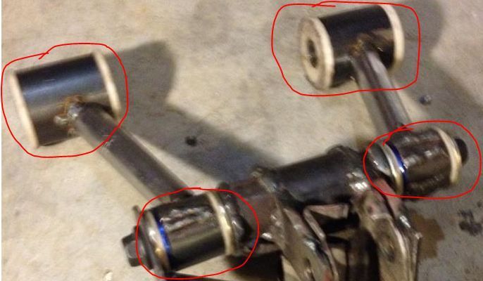
Where did you source your bushings and outer sleeves?
West coast fiero 84-87 front bushing replacement kit .They have to be machined to fit the tubes shown .They actually fit stock control arms .I do not know if these are still available or not.These arms are just a mockup and the outers are getting machined to fit proper tubing now .
I really need to drop by one of these days to check out what all you are building after all you are only a half hour or so away. Dan
------------------
DARN Cars now open with Over 30 years wiring experience between cars and trade as an avionics technician in both Canadian Air Force and civilian aviation. Over 25 years experience building and modifying cars. Over 10 years of full Fiero engine swaps and harnesses building and still going.
That would be great .I work 12 hour rotating shifts so I will PM you my cell .Easiest way to get hold of me .Upcoming Super Bowl weekend :working nights lucky me .


 right from the locost site. I had not seen ones with custom knuckles however I will check them out