I used to offer a service reworking the rear 88 knuckles. The hole for that long bolt goes thru is over-sized. When GM made them they drilled that hole and probably with one drill bit. Doing that creates a tapered hole so one end is usually even larger. They should have been drilled under size and reamed. Plus they go slightly larger so it makes the assembly line move faster during assembly. My repair was to counter-bore for around tube steel inserts. This made the hole very precise and the long bolt had maybe .001 or so play. They were so labor intensive I decided it was just too much work no matter what I would charge for that service so I dropped that. Talking to someone today about that I mentioned the weld in washer idea I have had. If I find large outer diameter washers and ream the ID so they fit the long bolts very precise and then the customer has them welded to both sides of the casting. The casting is a cast steel and accepts weld. Once installed and tightened up there is no movement and thus no wear. So a 1/8" thick washer should work. This would spread the suspension arms out about 1/4" but both rubber and poly have some give and that should not affect anything.
Would be a cheap and easy fix.
------------------ Rodney Dickman
Fiero Parts And Acc's Web Page: All new web page!:www.rodneydickman.com Rodney Dickman's Fiero accessories 7604 Treeview Drive Caledonia, WI 53108 Phone/Fax (262) 835-9575
I think you would find that it would be a very temporary fix. All of the loads normally spread over the entire surface area of the bore would end up acting on the 1/8" thick washers at either end. I believe that the concentrated load would either wear out the washer holes very quickly or the washers would wear a groove in the long bolt. The part that wore would depend on the hardness of the washer relative to the bolt. Much like this Jeep spring eye bolt which was under similar conditions:
Edit to add: A alternative is to have a good machine shop with a CNC mill drill out the lower knuckle bore to 1/2" (12.770 mm) diameter, up from the stock 12mm diameter. This also makes finding the correct strength long bolt much easier since SAE bolts are more common in that length than metric ones.
[This message has been edited by Bloozberry (edited 09-11-2014).]
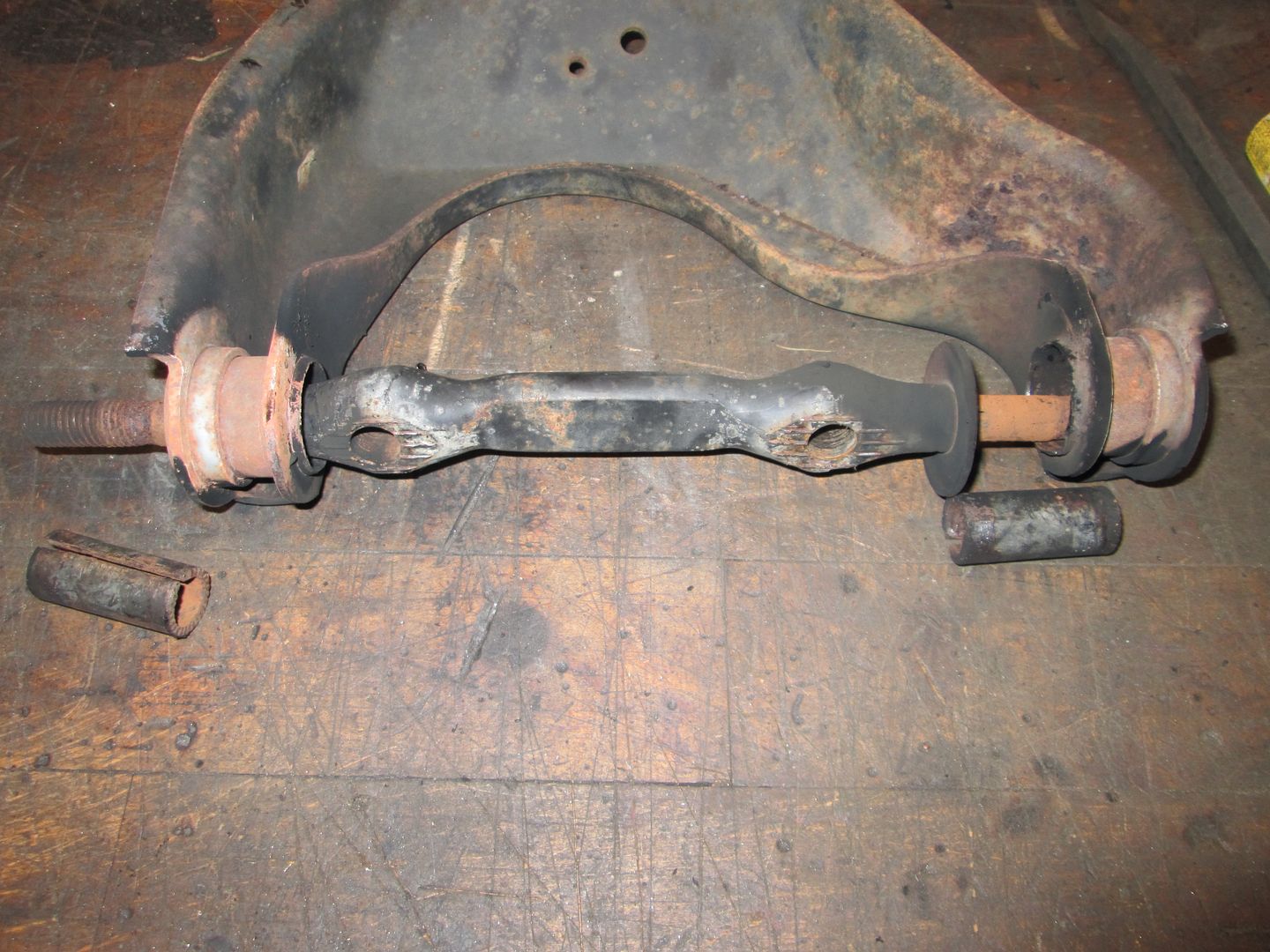
I went with the 1/2" bolt idea, it tightened everything up considerably. Since the 1/2" bolt is only .026" larger O.D it may not clean up excessively elongated holes though. Pushing through the lateral link and adjustable link bushings, with a little anti-seize was uneventful and I could still rotate the bolt in the bushing. (with a wrench)
Originally posted by Bloozberry: I think you would find that it would be a very temporary fix. All of the loads normally spread over the entire surface area of the bore would end up acting on the 1/8" thick washers at either end. I believe that the concentrated load would either wear out the washer holes very quickly or the washers would wear a groove in the long bolt.
Since the properly tightened bolt would not move, there would be no wear. It would be a suitable fix.
BTW the loads is not normally spread out over the entire surface area of the bore -- not only is that not possible because of stress/strain distribution but even with a simplified model of the bolt being perfectly rigid, the bore would have to precisely fit the bolt for that to happen.
That might be true if the bolt were holding two or three flat plates together in shear but that's not the case here. The bolt is only holding two relatively small cross sectional area tubular bushing ends against the casting. Lateral loads are transmitted as bending stresses not shear stresses to the bolt since the centerline of the lateral links is offset from where bolt enters the knuckle on either side. The bending stresses are reacted mostly by the knuckle material surrounding the hole, but are also reacted by the surface area of the entire bore as the hole is larger than the bolt and the bolt will bow within the bore. In my opinion, that is why the holes become egg shaped in the first place. If then, a 1/8" thick washer is welded to an oversized hole as a repair scheme, then the only material reacting the bending stresses at the surface of the knuckle is the material thickness of the washer. In my opinion, that will result in the condition I described above. But I'm open to debate and alternate views.
I don't know a lot about welding, but I was under the impression that welding cast iron wasn't an easy thing to do? ?
Looks like forged steel, not cast iron to me.
I have access to a CNC mill an could easily fix a bunch of these. The problem is that setup and fixturing is only worthwhile for doing runs of at least 20-40 knuckles... which will never happen.
Originally posted by Bloozberry: The bolt is only holding two relatively small cross sectional area tubular bushing ends against the casting. The bending stresses are reacted mostly by the knuckle material surrounding the hole, but are also reacted by the surface area of the entire bore as the hole is larger than the bolt and the bolt will bow within the bore. In my opinion, that is why the holes become egg shaped in the first place. If then, a 1/8" thick washer is welded to an oversized hole as a repair scheme, then the only material reacting the bending stresses at the surface of the knuckle is the material thickness of the washer. In my opinion, that will result in the condition I described above. But I'm open to debate and alternate views.
Interesting and descriptive explanation of what seems to be happening. It doesn't take long for the process to start, in my case I had 54,000 miles on the odometer. Do you suppose that as the small cross sectional area of the tubing, as it flexes against the softer casting material gnawing into it, would cause the bolt to loosen, speeding up the process? The nice thing about the spherical rod ends is the thick cross sectional area to help spread out the stresses at that critical point.
One solution may be replacement link bushings, with a large cross sectional area?
Originally posted by Jims88: Do you suppose that as the small cross sectional area of the tubing, as it flexes against the softer casting material gnawing into it, would cause the bolt to loosen, speeding up the process?
It's possible, but I haven't seen any knuckles where the material is chewed up around the lower bolt holes. Perhaps others have.
How about tapping the holes out to 9/16 then having studs made up that are 9/16 thread to screw into the holes and 1/2 inch to mount the control arms? There would be no flex and all loads would be directly handled by the spindle. I would think you would want the 9/16s portion of the stud to go an inch into the spindle.
How about tapping the holes out to 9/16 then having studs made up that are 9/16 thread to screw into the holes and 1/2 inch to mount the control arms? There would be no flex and all loads would be directly handled by the spindle. I would think you would want the 9/16s portion of the stud to go an inch into the spindle.
I used to offer a service reworking the rear 88 knuckles. The hole for that long bolt goes thru is over-sized. When GM made them they drilled that hole and probably with one drill bit. Doing that creates a tapered hole so one end is usually even larger. They should have been drilled under size and reamed. Plus they go slightly larger so it makes the assembly line move faster during assembly. My repair was to counter-bore for around tube steel inserts. This made the hole very precise and the long bolt had maybe .001 or so play. They were so labor intensive I decided it was just too much work no matter what I would charge for that service so I dropped that. Talking to someone today about that I mentioned the weld in washer idea I have had. If I find large outer diameter washers and ream the ID so they fit the long bolts very precise and then the customer has them welded to both sides of the casting. The casting is a cast steel and accepts weld. Once installed and tightened up there is no movement and thus no wear. So a 1/8" thick washer should work. This would spread the suspension arms out about 1/4" but both rubber and poly have some give and that should not affect anything.
Would be a cheap and easy fix.
There are several ways the bolted joint can fail, as discussed above. Tightening the clearance to the through-bolt doesn't fix any of them.
In order for the joint to work as designed, the bolt needs a certain minimum preload. Because the inner sleeves on the bushings are butted, the joint CAN NOT have enough preload because applying it will spread the inner sleeves of the bushings. Also, the "teeth" at the ends of the inner sleeves can dull/blunt as the bushing moves around and further relax the preload on the bolt.
My suggestion for a bolt-in solution is to build a set of lateral links designed around these or similar parts:
Lemforder 34756-01 - sealed automotive grade spherical bearings which have been mass-produced and used across the Mercedes product line for the last 25 or 30 years. The ZF webcatalog lists its length at 48mm, so it's probably a little bit long to fit into the cradle mounting points for the lateral links. (I haven't verified with a measurement yet)
The solid center sleeve of a unit like this would allow the proper amount of preload--say 80 ftlbs--to be applied to the bolt. Then it doesn't matter if the hole's worn, as the bolt isn't going anywhere.
[This message has been edited by Will (edited 09-13-2014).]
Originally posted by Will: There are several ways the bolted joint can fail, as discussed above. Tightening the clearance to the through-bolt doesn't fix any of them.
I don't think you are seeing the problem and solution for what it is. The joint consists of a long bolt being passed through a cast steel knuckle (cam-a-lot I am pretty sure this is a cast piece, not forged) that has a through hole in it. Any free clearance between the bolt and the knuckle will result in cold forming of the through hole in the knuckle over time as it is subjected to cyclical loading. The service that Rodney offered was a stop-gap fix for the cold forming issue on the knuckle.
quote
Originally posted by Will: My suggestion for a bolt-in solution is to build a set of lateral links designed around these or similar parts:
Lemforder 34756-01 - sealed automotive grade spherical bearings which have been mass-produced and used across the Mercedes product line for the last 25 or 30 years. The ZF webcatalog lists its length at 48mm, so it's probably a little bit long to fit into the cradle mounting points for the lateral links. (I haven't verified with a measurement yet)
The solid center sleeve of a unit like this would allow the proper amount of preload--say 80 ftlbs--to be applied to the bolt. Then it doesn't matter if the hole's worn, as the bolt isn't going anywhere.
It does matter if the hole is worn in the Fiero knuckle! The real solution would be a knuckle that does not have a through hole, but two separate threaded bolt holes that would attach the links separately. Using bushing at the ends of the links similar to what you have pictured would allow for the pre loading of the bolts. But such a design would have a risk of shearing the retention bolts at the point where the bushing contacts the knuckle.
In regards to the knuckle being cast iron, I can't say for sure about the 88 knuckle but I would assume that it's grey cast. I have done welding on the 84 to 87 knuckles though and can say for sure that they are cast iron and the resulting strength of the weld after was extremely brittle. The weld had no strength and would usually crack while cooling, or break off in the vice under hand loads.
Having said this there is a way to weld it as after a bunch of testing, I did find a way to weld it and maintain adequate strength. I experimented with a few different documented methods and found the one to have the best strength to be the copper rod with pre-heating the part and cooling afterwards. However even though the copper alloy had more strength it wasn't very forgiving in the technique (since the part may be out of the oven too long while us armatures mess around with the setup). So what I ended up doing was using a nickle alloy rod. I pre-heat the knuckle to between 350 and 400 degrees C (sorry I'm Canadian), and welded the break ears (that's what I was working on at the time) on immediately. Then I put the knuckle back in the oven for an hour and then slowly dropped the temperature 50 degrees C every 30 minutes until cool.
Good luck.
I think you are better off using a counterbore bit and then press fitting a bushing in to both ends. Also I would put a slight chamfer on the bushing outside facing ID so that it would accommodate an o-ring seal to keep the bolt from seizing in it's bore.
Aaron
.
[This message has been edited by aaron88 (edited 09-13-2014).]
Originally posted by aaron88: I think you are better off using a counterbore bit and then press fitting a bushing in to both ends. Also I would put a slight chamfer on the bushing outside facing ID so that it would accommodate an o-ring seal to keep the bolt from seizing in it's bore.
True but very hard to offer a do it yourself kit. I'm still pondering this. Ideally I would like to offer a do it yourself kit of some type.
------------------ Rodney Dickman
Fiero Parts And Acc's Web Page: All new web page!:www.rodneydickman.com Rodney Dickman's Fiero accessories 7604 Treeview Drive Caledonia, WI 53108 Phone/Fax (262) 835-9575
I am pretty sure the 88 rear uprights are a ductile cast iron. They can bend slightly, but when you machine it (like boring it for a larger wheel bearing), the chips are very, very small like cast iron vs being curled like steel. It also cuts with a hack saw much, much easier than steel. Its not a material I would recommend welding by any method.
By definition, once the two pieces in a bolted joint have any relative movement, the bolted joint has failed. So as long as the bolted joint doesn't fail, the hole elongation in the upright is pretty much irrelevant. All bolted joints are supposed to be designed for zero relative movement between the two parts.
In the event the bolted joint fails, then having a tighter hole will temporarily result is less toe change, until the moving parts start to wear. The bolted joint can fail because the installed failed to properly torque the bolt, or the sleeves in the bushings compressed allowing the bolt to loose it clamp load. The stock sleeves have a split down the middle, so they tend to deform if over tightened. Poly is worse, because the sleeves are a thinner wall material and easily deform. This is why its quite common for someone to install poly in the 88 rear and torque it down, then 1 week later have the rear end moving all over the place and find the bolt loose (even if they double nut it).
The rod end lateral link upgrade is very nice in that is eliminates bushing deflection, but more importantly, its end connection with the bolt is very hard and will not compress/deform. So tighten the bolt once and you are done. It will not deform and lose its clamp load. With these, it doesn't matter what condition the hole is, but I normally use a heavy/hard washer between the upright and the rod end because the side of the upright is often worn and might not allow the rod end to seat properly.
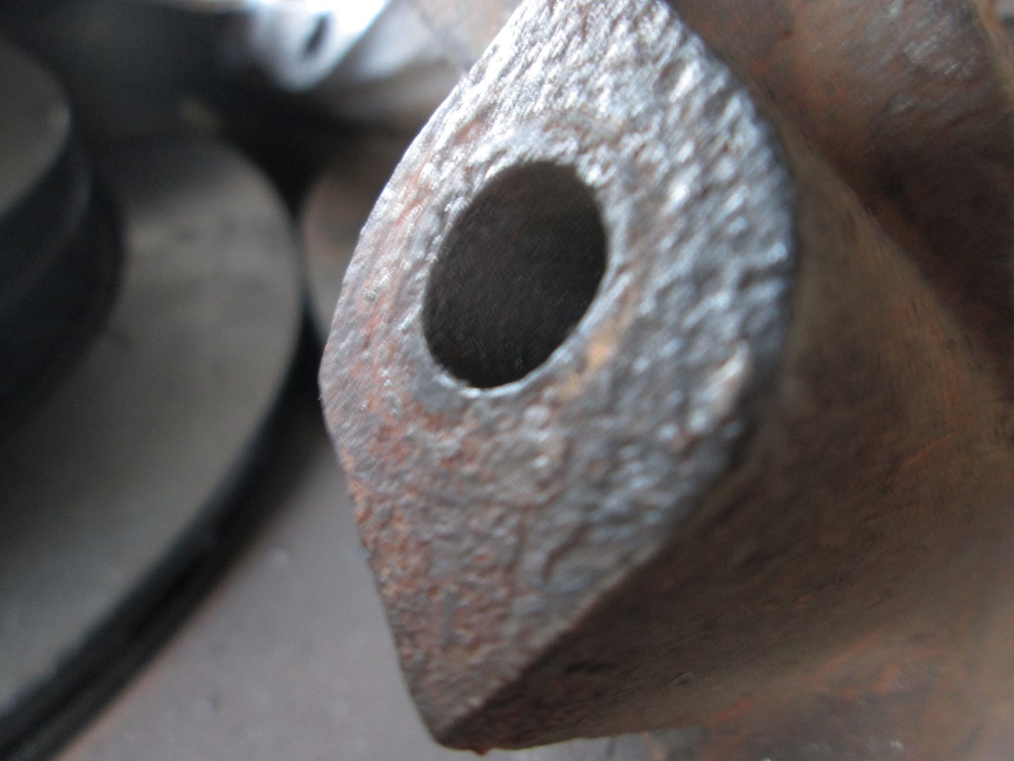
I happen to have more than my fair share of 88 rear uprights on the shelf and you can see the various stages of conditions with them. Here is one that has always had the lateral link bolt tight.
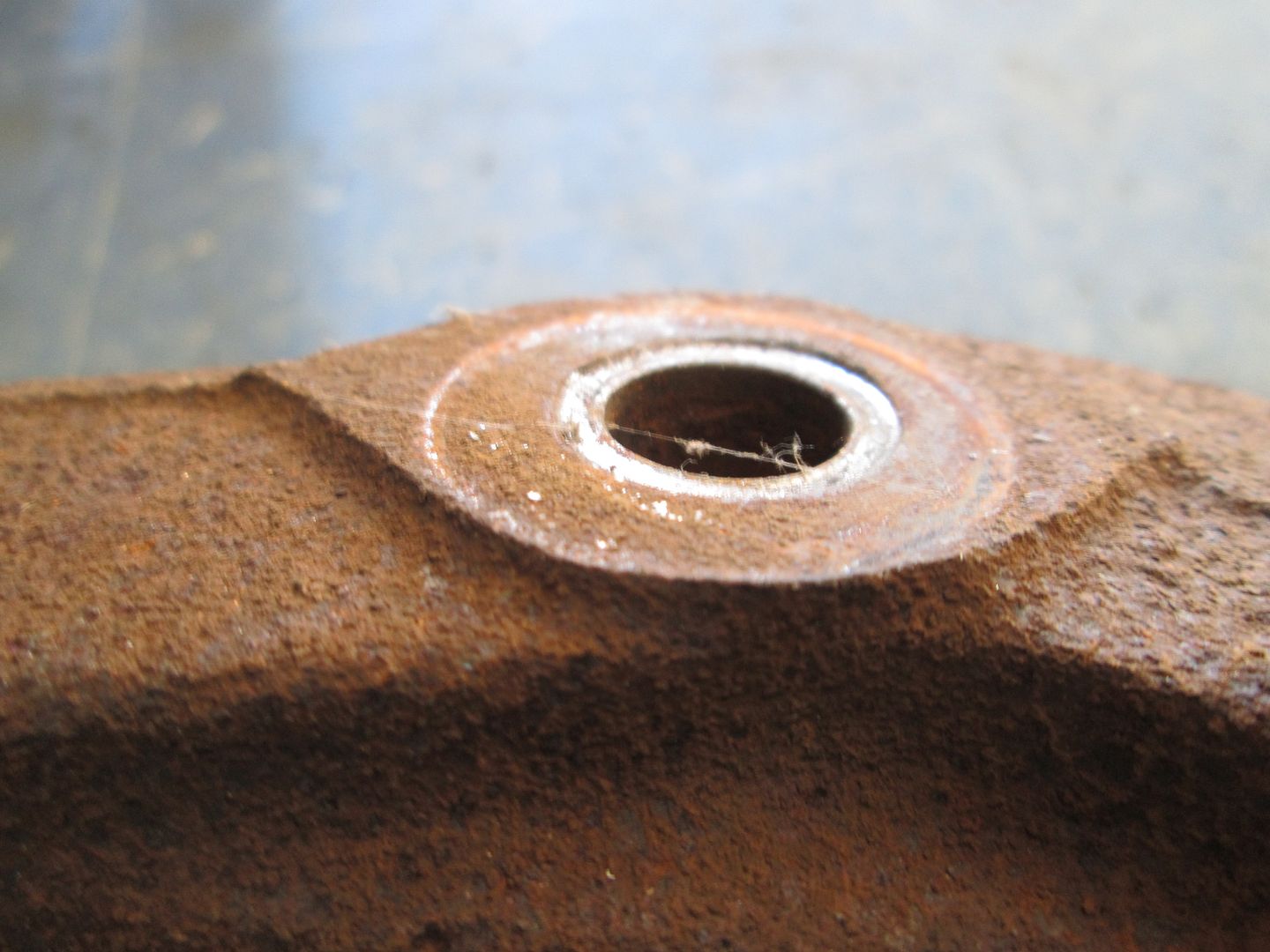
Here is one where the bolt was slightly loose, but the hole was snug. You can see the area where the bushing sleeve made contact has been worn down slightly.
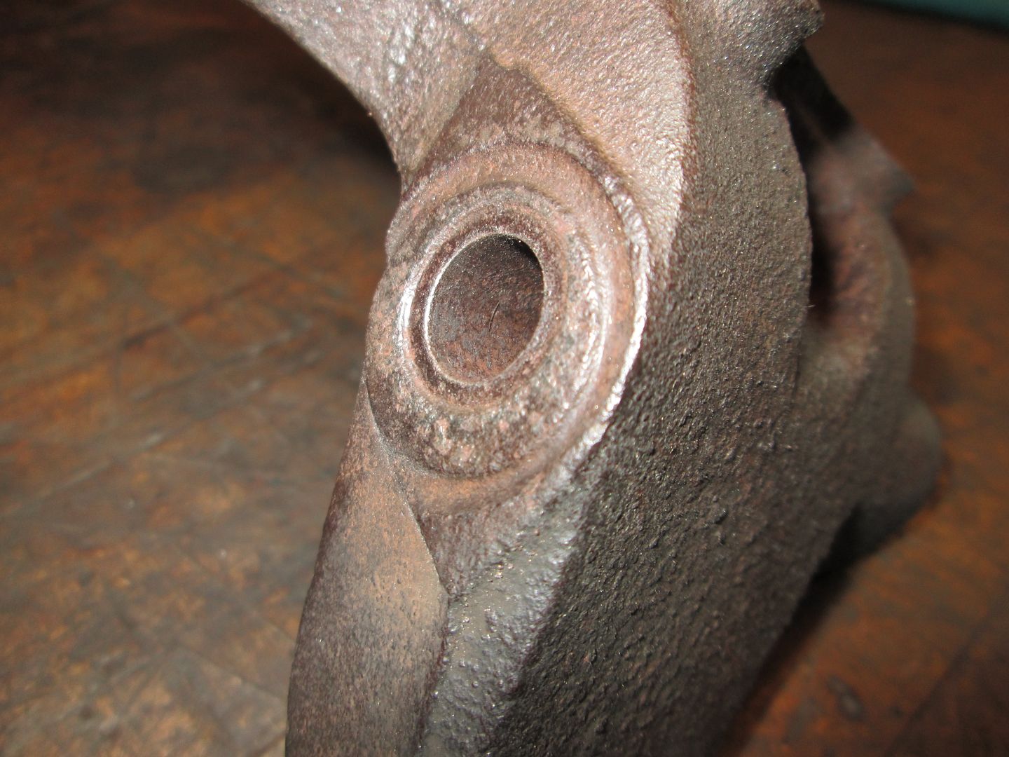
Here is one where the bolt was loose and the hole is slightly enlarged. The wear pattern from the bushing is slightly larger as well as the outer bushing sleeve started to make contact and wear into the upright as well.
True but very hard to offer a do it yourself kit. I'm still pondering this. Ideally I would like to offer a do it yourself kit of some type.
We really do need some kind of low cost service repair solution for 88 knuckle. Could the washer idea work using a taper/cone type washer that would use the O.D. of the knuckle to center up on, so the bolt tension can clamp it, with out welding? The longevity may be questionable, but if the cost is low just throw them away and buy new ones. With fieroguru's pictures this is what I was trying to illustrate.
Not as much area to secure it here though, maybe Loctite.
[This message has been edited by Jims88 (edited 09-14-2014).]
If you wanted something that could take care of the slop in the bolt hole and repair any previous damage from the bushing sleeves... Countersink the ends of the upright and have some hard countersunk/tapered washers made that fit snug to the bolt.
The kit could include the countersunk bit (most people don't have one of these - but I do!), the tapered washers, new bolt, and lock nut.
[This message has been edited by fieroguru (edited 09-13-2014).]
Here is one where the bolt was loose and the hole is slightly enlarged. The wear pattern from the bushing is slightly larger as well as the outer bushing sleeve started to make contact and wear into the upright as well. [/QUOTE]
Great pictures!
This one is unique, it looks like the rubber material let go on the outer sleeve so it could walk into the knuckle? If that is the case it would explain why the factory used the large washers on the ends of the lateral links to keep them from sliding off.
[This message has been edited by Jims88 (edited 09-13-2014).]
Most times when bolts and bushings move in ways they should not, something is wrong. Mostly the bolt/nut cause the problem and the rest are side effects. In your knuckle problem... Inner sleeve and hard bolt will "eat" the knuckle when parts/bolt have rust problems, low torque, aftermarket poly, etc.
Even Class 10.9 or SAE Grade 8 bolts can and will stretch or bend from hitting too many big bumps. Big knuckle bolt is fairly small diameter + long = the bolt can fail easier. Re-torquing might work or not. If bolt is stretched then tightening can break it now or soon. 88 knuckle bolt Is Not same as long bolt for 84-87 front UCA. Front bolt is connected to frame and insulated by bushings from any impact from CA or knuckle. Back 88 bolt is directly connected to hub/knuckle and sees all impact and road/tire vibration.
Fixing worn knuckle? Be careful. Adding a sleeve might make cast/whatever iron too thin to hold up in the long run.
Even after fix/replace the knuckle... You still need to check that bolt isn't showing sign of stretching etc or you will be fixing/replacing the knuckle again. Check every time you change engine oil. If you find anything wrong or need to fix a dead bushing then get a new bolt and Correct nut. I'm guessing GM used a lock nut here.
Note that Many torque specs are on Dry threads for a reason. Any lube, including anti-seize, on the thread then OE torque spec can/will stretch the bolt and could make it fail soon. Lube can/will interfere w/ locking of nut then Nut can back off. When using bolt and nut... Avoid use torque wrench on the bolt. Knuckle etc can cause false torque resulting in bolt is under torque spec.
This bolt's nut is torqued in two steps. Torque the Nut to 50 N-m (37 ft/lbs) then add 90° more. 88 SM, Pages 3D-8
------------------ Dr. Ian Malcolm: Yeah, but your scientists were so preoccupied with whether or not they could, they didn't stop to think if they should. (Jurassic Park)
I don't think you are seeing the problem and solution for what it is. The joint consists of a long bolt being passed through a cast steel knuckle (cam-a-lot I am pretty sure this is a cast piece, not forged) that has a through hole in it. Any free clearance between the bolt and the knuckle will result in cold forming of the through hole in the knuckle over time as it is subjected to cyclical loading.
I don't think you understand bolted joints. We have essentially this same discussion about flywheel bolts on a regular basis. GM's single shear design for mounting the bushing is junk. If the side of the bolt and the side of the hole ever see cyclical loading against each other, the joint has already failed. Wallowing out the hole is a result of the failure, not a cause.
A bolted joint is held together by friction between the two components. This friction is achieved via clamp load obtained by tightening the bolt. The problem with the '88 suspension is that THE BOLT CAN NOT BE TIGHTENED enough to achieve the requisite clamp load... Try it... if you tighten the bolt, you'll crush/spread the inner sleeves of the bushings. If you put spherical bearings on it, the bolt can be tightened to 80 fltbs (about the limit for a 12mm class 10.9 bolt). At that point the clamp load of the bolt is enough that the spherical bearing and knuckle have enough friction that lateral loads on the suspension will not cause them to slide across each other. Clearance between the hole and the bolt is not relevant. Bolt in a set of rod end links and get an alignment... problem solved.
quote
Originally posted by lateFormula: The service that Rodney offered was a stop-gap fix for the cold forming issue on the knuckle.
Correct.
quote
Originally posted by lateFormula: It does matter if the hole is worn in the Fiero knuckle! The real solution would be a knuckle that does not have a through hole, but two separate threaded bolt holes that would attach the links separately.
Fine... go have one cast
quote
Originally posted by lateFormula: Using bushing at the ends of the links similar to what you have pictured would allow for the pre loading of the bolts. But such a design would have a risk of shearing the retention bolts at the point where the bushing contacts the knuckle.
No it doesn't... if the hole and bolt have contact, the joint has already failed.
[This message has been edited by Will (edited 09-16-2014).]
Ideally I would like to offer a do it yourself kit of some type.
quote
Originally posted by Will:
Bolt in a set of rod end links and get an alignment... problem solved.
Probably should include a new bolt with the rod-end link kit.
I'm pretty sure I've seen rod-end versions of the sealed spherical bearing I linked above, but didn't note them as they weren't what I was looking for at the time.
The ideal repair in my opinion is to counter bore and press in a steel sleeve of some type. Problem is to use a counter bore the ID of the hole has to be close to the OD of the pilot of the cutter will enlarge the counter bored hole oversize making a sleeve loose. When I did them I reamed the hole to a precision .501" or so. Then I could use my counter bore to cut a precision hole for the sleeve but undersized. I then reamed the counter bored hole for the sleeve. Then I reamed the ID of the pressed in sleeves so the long bolt passed thru but did not bind. I'm not sure if a tapered piece is a good option. All the pressure pushing outward may make the casting crack?
An idea is a counter bore reamer with a very long pilot. Maybe that would create a hole that is precision enough to accept a steel tube. I think a tool sharpener could take a long flute reamer and grind the end into a pilot and make the cutting edge again. The pilot could be maybe 1" or longer. But you still have the factory hole which is not precise. One side may work well. The other side might wobble around and go oversize. A end user would use a hand drill to do this reaming.
Just no easy answer on this one (yet?). ------------------ Rodney Dickman
Fiero Parts And Acc's Web Page: All new web page!:www.rodneydickman.com Rodney Dickman's Fiero accessories 7604 Treeview Drive Caledonia, WI 53108 Phone/Fax (262) 835-9575
[This message has been edited by Rodney (edited 09-16-2014).]
The ideal repair in my opinion is to counter bore and press in a steel sleeve of some type.
I disagree. This doesn't solve the problem, which is related to the design of the bushing, not the knuckle. The damage to the knuckle is a result of the problem, but is not the problem.
The problem is:
The bushing is held in single shear, allowing rotational loads from the bushing to work on the bolt. The inner sleeve of the bushing can flex, because it is rolled and butted, but not welded. Over time, flexion of the sleeve can move the tines cut into the end of the sleeve such that they gouge into the knuckle. The the bushing tines gouging into the knuckle reduces the total length of the assembly, which reduces the clamp load the bolt holds on the knuckle and bushings. As the clamp load is reduced, the bushing sleeves can move more.
It is not possible to tighten the bolt enough to avoid this because doing so would crush the bushing sleeve.
What's needed is a new bushing design with a sleeve that either has a much thicker wall and possibly has large diameter shoulders at either end such that the assembly can take the 80+ lbft of torque allowable on the bolt. The out-of-round hole in the knuckle then becomes irrelevant since the bolt is only providing a clamping force. The larger diameter, thicker walled sleeve will obviously limit the thickness allowable for the (rubber) bushing material, but that is not a problem since some here have used solid spherical bearings and haven't reported any markedly worse noise, vibration or harshness for this particular area.
Originally posted by Bloozberry: but that is not a problem since some here have used solid spherical bearings and haven't reported any markedly worse noise, vibration or harshness for this particular area.
Correct... there's no perceptible change in noise or ride quality from going to spherical bearing lateral links.
Where the lateral links contact the knuckle is spherical movement needed? Would pressing an oil impregnated bronze bearing into the lateral link, with a thick wall internal bushing; have a negative effect on required motion?
The forward lateral link is shorter than the rear lateral link to provide toe changes through the suspension's travel, so some degree of spherical movement is probably required at the knuckle to prevent binding. It's possible that the inboard bushings could handle that task by themselves allowing what you suggest though.
Where the lateral links contact the knuckle is spherical movement needed? Would pressing an oil impregnated bronze bearing into the lateral link, with a thick wall internal bushing; have a negative effect on required motion?
Besides the two lateral links being different lengths, the trailing link moves in an arc that the lateral links must follow. This means they will see some front to back motion along the rigid axis of the bushing. This is one of the reasons rod ends are hard to beat for this application, zero bushing deflection, but good range of motion to accommodate suspension movement.
Is there enough meat on the poly bushings to change to a larger ID and use a thicker walled tube through the center that can handle the forces without deforming? Desire would be that you could torque the bolt down tighter without crushing the tubes and adequately lock everything together while still having some compliance from the poly to account for non-rotational deformation requirements?
Maybe combine that with changing to a 1/2 inch bolt to reduce the play in the knuckle hole a little bit?
The forward lateral link is shorter than the rear lateral link to provide toe changes through the suspension's travel, so some degree of spherical movement is probably required at the knuckle to prevent binding. It's possible that the inboard bushings could handle that task by themselves allowing what you suggest though.
quote
Originally posted by fieroguru:
Besides the two lateral links being different lengths, the trailing link moves in an arc that the lateral links must follow. This means they will see some front to back motion along the rigid axis of the bushing. This is one of the reasons rod ends are hard to beat for this application, zero bushing deflection, but good range of motion to accommodate suspension movement.
Is there enough meat on the poly bushings to change to a larger ID and use a thicker walled tube through the center that can handle the forces without deforming?
Maybe combine that with changing to a 1/2 inch bolt to reduce the play in the knuckle hole a little bit?
I think I have seen some pictures of the poly kits with bushings laid out separately. I haven't purchased a poly kit, but if they are separate; I wouldn't think it would be to difficult to drill them out for over sized bushings.
Drilling existing bushings out for a larger thicker tube would be an easy way to test the concept, but for production, I was figuring someone (Rodney) could produce poly bushings with the ID already larger than "typical". I'm just trying to muse solutions to the problem that don't require changes to the knuckle or arms.
As for the tube being separate, I'm no suspension guy, but in my limited experience, motion on poly bushings like that has always been on the ID (the tube rotates inside the poly). And because of that the tubes have to be separate since that's where the pivot point is. That's one of the things that fundamentally set poly apart from the rubber style.