Pennock's Fiero Forum
  Technical Discussion & Questions
  Temp gauge pegging fix (questions)

Post New Topic  Post A Reply
Email This Page to Someone! | Printable Version


next newest topic | next oldest topic
Temp gauge pegging fix (questions) by Enix
Started on: 05-07-2014 12:18 AM
Replies: 8 (847 views)
Last post by: Enix on 05-14-2014 09:06 PM
Enix
Member
Posts: 66
From: Clackamas, OR
Registered: Mar 2007


Feedback score: (2)
Leave feedback

Rate this member

Report this Post05-07-2014 12:18 AM Click Here to See the Profile for EnixSend a Private Message to EnixEdit/Delete MessageReply w/QuoteDirect Link to This Post
I have been reading up on how to fix the pegging temp gauge problem (here: http://www.fierosails.com/tempgage.html) and am left with two questions:

1: the info in the article is referencing 84 and 88 models; has anyone done this exact fix to 85-87 2.8s with success?

2: the plastic connector on my temp sensor wiring loom has completely melted away (as most do) and although I can find out which wire is for the idiot light and which is for the gauge needle, I cannot find any references to which pins do what on the actual sensor; can anyone tell me which pin on the sensor is for the idiot light and which pin is for the gauge needle?
(the reason I ask is because I'm supposed to swap the wires... but I can't swap them if I don't know which orientation they were in to begin with )

Thanks in advance! I'll be completing the wire swap this weekend.
IP: Logged
PFF
System Bot
phonedawgz
Member
Posts: 17106
From: Green Bay, WI USA
Registered: Dec 2009


Feedback score:    (23)
Leave feedback


Total ratings: 291
Rate this member

Report this Post05-07-2014 12:55 AM Click Here to See the Profile for phonedawgzClick Here to visit phonedawgz's HomePageSend a Private Message to phonedawgzEdit/Delete MessageReply w/QuoteDirect Link to This Post
Yes it works for 84, 85, 86, 87, 88. Both the 2.5 and 2.8 engines

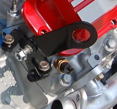
The temperature gauge sending unit has two functions. The wire that connects to the pin that is AWAY from the side notch is for the gauge. The wire that is close to the side notch is for the TEMP light (yes your Fiero has one).


AFTER COMPLETING THE DASH WIRE SWAP

Turn the key on but leave the engine off. Ground one of the wires. Then try the other. One should light the temp light. The other should make the temp gauge (or just pivot in your case) move. Then just make sure the wires are on the correct pins so the two devices work correctly.
The plastic shell on the temperature gauge sender connector tends to get brittle and fall apart. New plastic shells can be obtained from Rodney Dickman for $7.50 delivered to your mailbox. Damn cheap if you ask me.

http://rodneydickman.com/ca...h=21&products_id=174

[This message has been edited by phonedawgz (edited 05-07-2014).]

IP: Logged
Enix
Member
Posts: 66
From: Clackamas, OR
Registered: Mar 2007


Feedback score: (2)
Leave feedback

Rate this member

Report this Post05-07-2014 01:04 AM Click Here to See the Profile for EnixSend a Private Message to EnixEdit/Delete MessageReply w/QuoteDirect Link to This Post
 
quote
Originally posted by phonedawgz:

The wire that connects to the pin that is AWAY from the side notch is for the gauge. The wire that is close to the side notch is for the TEMP light (yes your Fiero has one).


So just to clarify: the above orientation you've listed needs to be swapped along with the wire swap at the dash?
The reason I ask is because I have a friend who says he's only ever done the swap at the dash and never at the sensor.

Thanks!
IP: Logged
phonedawgz
Member
Posts: 17106
From: Green Bay, WI USA
Registered: Dec 2009


Feedback score:    (23)
Leave feedback


Total ratings: 291
Rate this member

Report this Post05-07-2014 09:35 AM Click Here to See the Profile for phonedawgzClick Here to visit phonedawgz's HomePageSend a Private Message to phonedawgzEdit/Delete MessageReply w/QuoteDirect Link to This Post
If only one end is swapped the gauge and light won't work.

When I build engine swap harnesses I build the swap into them so only the dash end is needed.

I don't identify the wires by color but instead by testing. So if the dash swap was preformed the wire that lights the light/activates the gauge swaps but will still give you the correct results.

 
quote
Originally posted by phonedawgz:

The wire that connects to the pin that is AWAY from the side notch is for the gauge. The wire that is close to the side notch is for the TEMP light (yes your Fiero has one).


This is how the sender is built.

[This message has been edited by phonedawgz (edited 05-07-2014).]

IP: Logged
Enix
Member
Posts: 66
From: Clackamas, OR
Registered: Mar 2007


Feedback score: (2)
Leave feedback

Rate this member

Report this Post05-07-2014 05:53 PM Click Here to See the Profile for EnixSend a Private Message to EnixEdit/Delete MessageReply w/QuoteDirect Link to This Post
So I've done the wire swap at the dash:
- Light green wire from 11 has been moved to 13
- Dark green wire from 13 has been moved to 11

Went to swap the wires at the temp sensor and was grounding them (as people say to do) to find out which wire controls what.
I found the gauge wire easy enough (the gauge pegged as usual).
But when I grounded the idiot light, it didn't light up! The bulb has been tested as good, so why is the idiot light not turning on when it's grounded?
IP: Logged
Enix
Member
Posts: 66
From: Clackamas, OR
Registered: Mar 2007


Feedback score: (2)
Leave feedback

Rate this member

Report this Post05-07-2014 06:04 PM Click Here to See the Profile for EnixSend a Private Message to EnixEdit/Delete MessageReply w/QuoteDirect Link to This Post

Enix

66 posts
Member since Mar 2007
I know that the wire swap at the dash is correct because I triple checked the wire colors AND their associated pin locations.
Plus, I soldered each connection when I extended the wires. So connectivity shouldn't be an issue...
IP: Logged
Enix
Member
Posts: 66
From: Clackamas, OR
Registered: Mar 2007


Feedback score: (2)
Leave feedback

Rate this member

Report this Post05-14-2014 05:43 PM Click Here to See the Profile for EnixSend a Private Message to EnixEdit/Delete MessageReply w/QuoteDirect Link to This Post
 
quote
Originally posted by Enix:
...
But when I grounded the idiot light, it didn't light up! The bulb has been tested as good, so why is the idiot light not turning on when it's grounded?


Just for closure (and for historical reference in case anyone else faces this), some of the traces on the printed circuit board (on the rear of the instrument panel) were broken. The plastic film had separated in the lower corner behind the tach and severed the traces for the temp warning light and the e-brake light. I swapped out the circuit board and both lights work fine now.
IP: Logged
NW-Fiero
Member
Posts: 447
From: Pierce County - WA
Registered: Aug 2008


Feedback score: N/A
Leave feedback

Rate this member

Report this Post05-14-2014 08:03 PM Click Here to See the Profile for NW-FieroSend a Private Message to NW-FieroEdit/Delete MessageReply w/QuoteDirect Link to This Post
Enis I am at the point where the describe the no light. Will go home now and pull the dash out again and check that dang flexi circuit board..

Thanks..

.

------------------
Mark
' 85 2m6 3.4PR
In the Great Northwest!

IP: Logged
Enix
Member
Posts: 66
From: Clackamas, OR
Registered: Mar 2007


Feedback score: (2)
Leave feedback

Rate this member

Report this Post05-14-2014 09:06 PM Click Here to See the Profile for EnixSend a Private Message to EnixEdit/Delete MessageReply w/QuoteDirect Link to This Post
 
quote
Originally posted by NW-Fiero:

Enis I am at the point where the describe the no light. Will go home now and pull the dash out again and check that dang flexi circuit board..


My friend supplied me with the extra circuit board and it too had started to separate in the exact same spot (the lower corner below the tach), so it must be a common place for these to deteriorate. We just taped the new one back together with electrical tape because the copper traces weren't broken.
IP: Logged

next newest topic | next oldest topic

All times are ET (US)

Post New Topic  Post A Reply
Hop to:

Contact Us | Back To Main Page

Advertizing on PFF | Fiero Parts Vendors
PFF Merchandise | Fiero Gallery
Real-Time Chat | Fiero Related Auctions on eBay


Copyright (c) 1999, C. Pennock