Well I did the Speedhut gauge face swap, and I wasnt satisfied at all with the needle lighting. But honestly, the more I went into this project, the more I realized that you could simply swap some of those 194 sized LED bulbs into the cluster, but if you're like me, you'll find this very entertaining to do
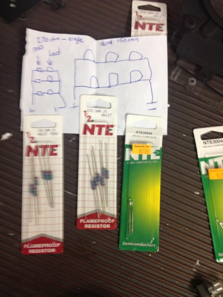
Step one: Gather parts necessary. You will need 5 3mm LED's for the main cluster, and 2 for the auxiliary gauges. You could probably use another size, but you will need to recalculate the size of the resistors. I went with white LED's for my white needles, but again, choose what color you will. Of course, you'll need wire. I just got one thin size, just a little thicker than the leads on the LED's, and another that is a little thicker, I went with 16 gauge. You will also need 2 sizes of resistors. Get a pack of 150 ohm and a pack of 270 ohm. Sorry the picture is blurry, but what it is saying is that when wiring 2 LEDs in series, wire in a 150 ohm resistor. When only doing one at a time, use a 270 ohm. It also says that you should be able to wire 3 LED's in series, but I could not get it to work. Might just be me though. Moving along!
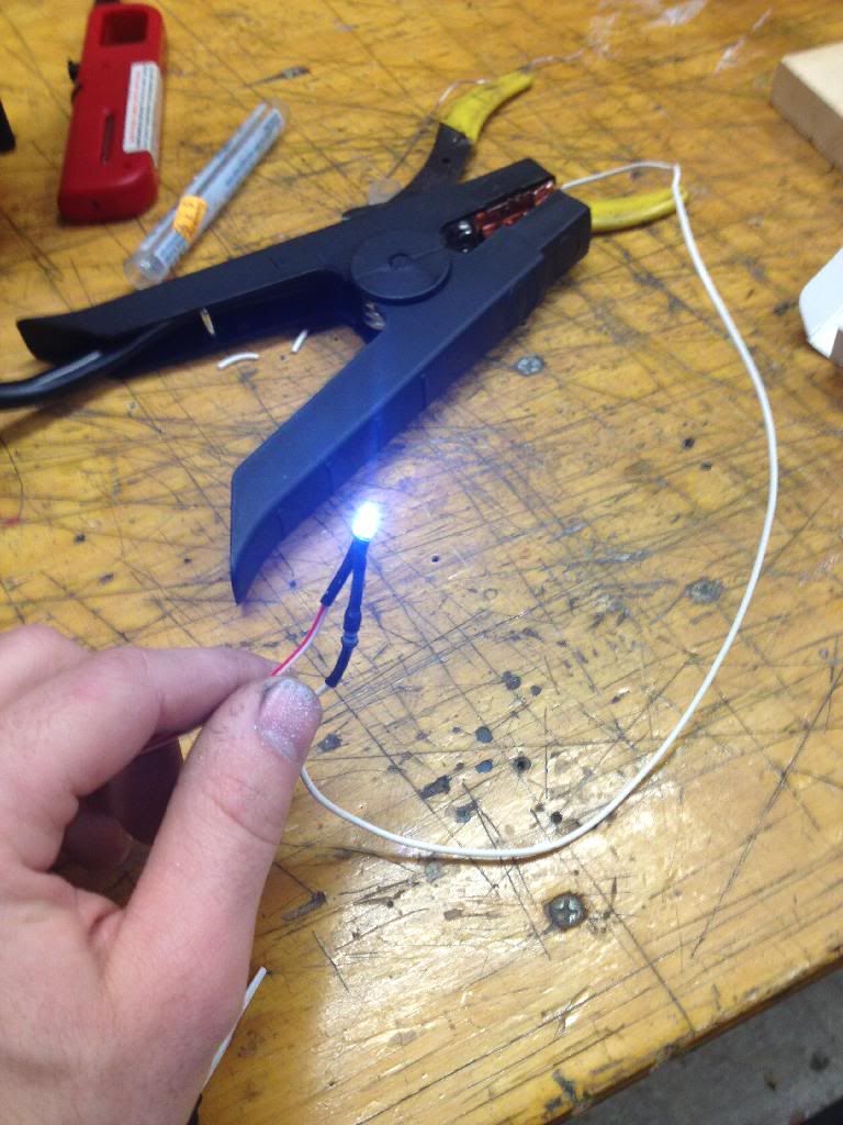
Step 2: Test your abilities!
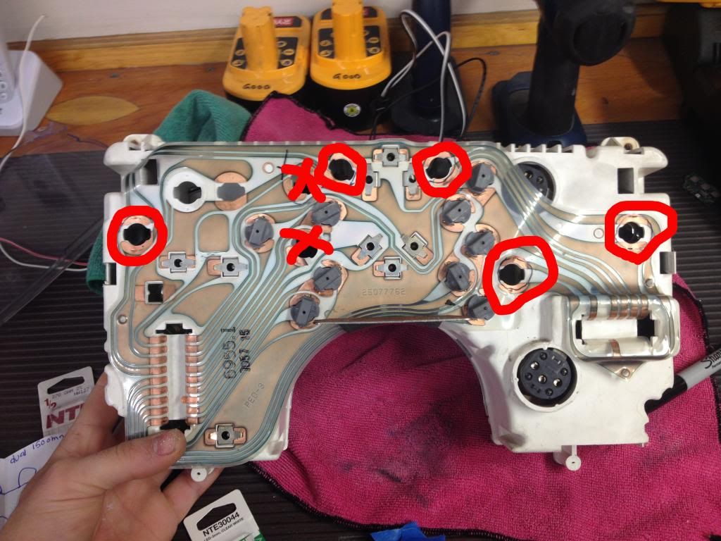
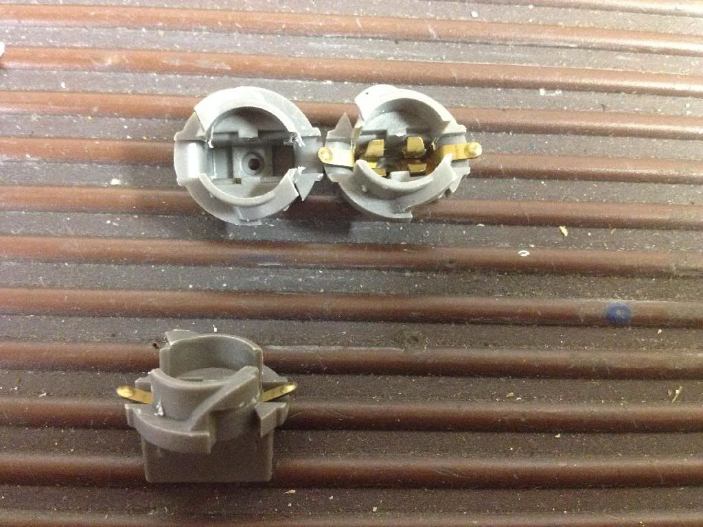
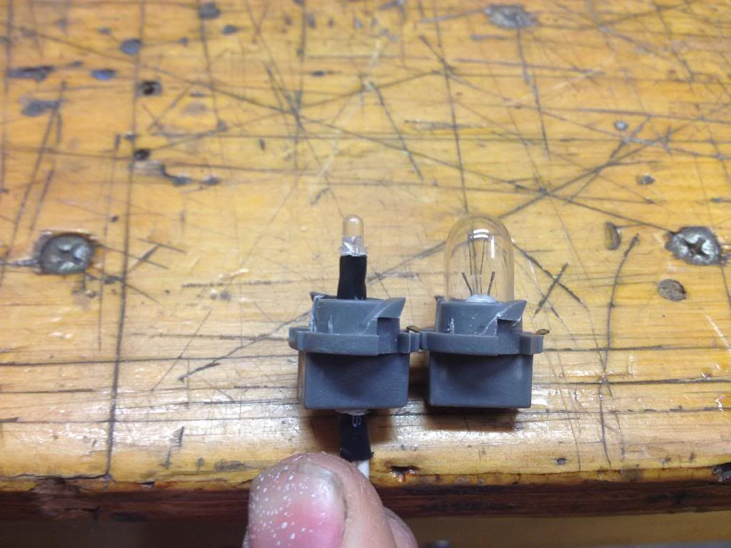
Step 3: Remove your cluster, and take out the 5 circled back light bulbs. The top "X" marks the shift light (I had to out source my bulbs, since one was missing. Figured I wouldnt need this one), and the lower one is a blank. Dont worry about touching those.
Step 4: Take the contacts out of the grey things, and drill a hole just big enough to fit the wires for your LED through.
[This message has been edited by grkboy707 (edited 01-05-2014).]
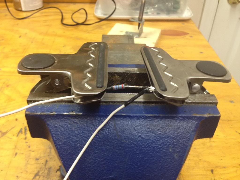
Youre gonna want to build an apparatus to help you solder. I just put 2 chip clips in a vise.
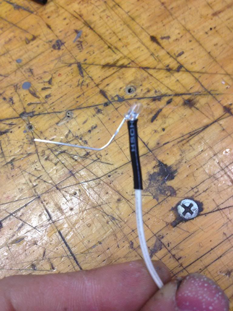
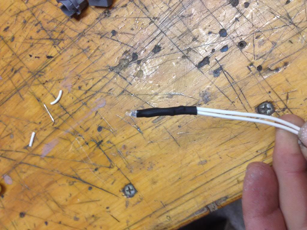
Step 5: Solder wire to LED and shrinkwrap. Do the same on the other contact, and shrinkwrap both together.
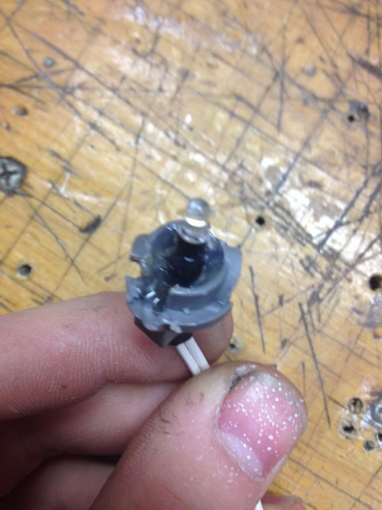
Feed that through the bulb socket, to the approximate height of a stock bulb.
Just for a little extra security, fill socket with hot glue, or equivalent.
Repeat this step, and wire a 150 ohm resistor into this 2 LED strand.
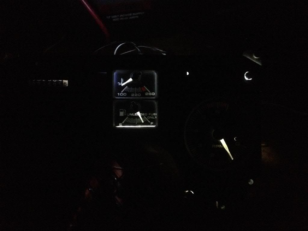
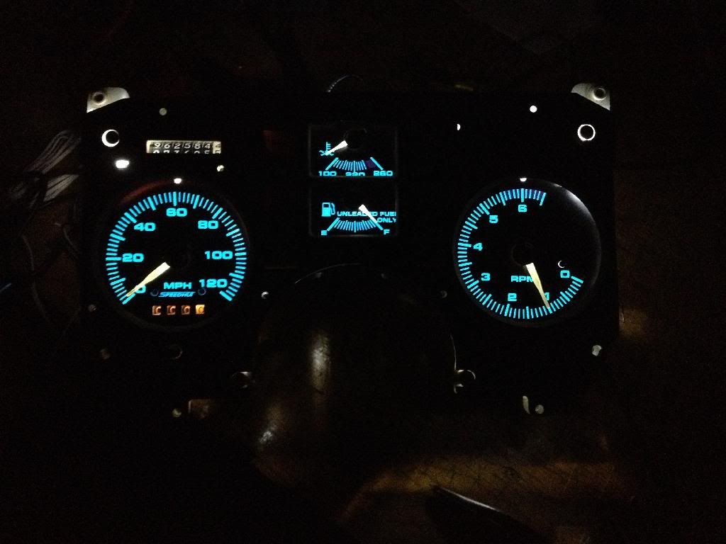
Step 6: Test! Needles look great if I do say so myself Theres some light coming through the Temp and gas gauge, but I just need to replace the weatherstripping that came out when replacing the faces.
Step 7: I only had one more LED on hand, so I wired it with a 270 ohm, and put it behind the RPM gauge.
So thats where I stand until Baynesville Electronics opens on Monday. Thanks for looking!
[This message has been edited by grkboy707 (edited 01-05-2014).]
DIY is easy w/o wires. Just solder LED and resistor to the metal parts of socket.
You can get 194 LED for $5-15 for 2-10 units... Try amazon etc.
------------------ Dr. Ian Malcolm: Yeah, but your scientists were so preoccupied with whether or not they could, they didn't stop to think if they should. (Jurassic Park)
DIY is easy w/o wires. Just solder LED and resistor to the metal parts of socket.
You can get 194 LED for $5-15 for 2-10 units... Try amazon etc.
Can you really solder right to the socket? That seems really tight in there. Unless you solder to the circuit board/sheet or whatever. And yeah, if I realized that the needles were lit just by the 5 bulbs, I probably would have just bought those. Oh well, I was in too deep by the time I realized that. This might even give the light more directly to the needles. Either way, I'm enjoying this process
I don't have one handy... from memory... Metal parts are held in place by pressure from bulb. The metal can be removed, solder to, then put back w/o any damage.
If needed push in some scrape plastic to make metal to stay put etc.
I don't have one handy... from memory... Metal parts are held in place by pressure from bulb. The metal can be removed, solder to, then put back w/o any damage.
If needed push in some scrape plastic to make metal to stay put etc.
Yeah, I removed the metal parts already, it just seems that space is very limited. I have seen people coil romex cable around a solder gun and have a strand sticking out though. That'd be your best bet in my opinion. Too late though
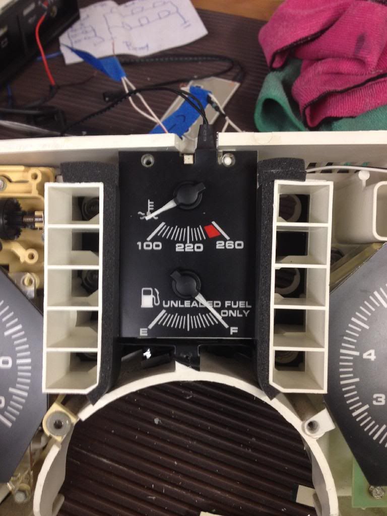
I wasnt able to make it to buy LEDs, but I was able to make it to Home Depot to get some small weatherstripping to block the light from going on the temp/ gas gauges.
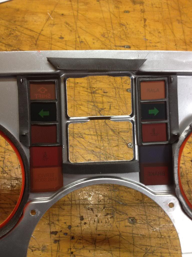
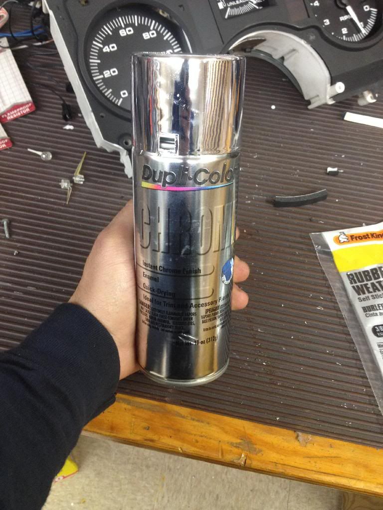
You may notice that instead of orange, mine is chrome. Im almost positive that without doing that, my odometer would still be orange. Thats thanks to this guy\/
Now you may be able to get this with glossy white, but I liked this option. I also may spray everything but the odometer surround flat black to further cut down the light.
Originally, im not sure what it's called. The light was reflected off the orange cover and projected on the face o the gauges. My Speedhut gauge faces are lit within the actual gauge face. Some sort of witch craft technology, but it makes it easy to be lit evenly
DIY is easy w/o wires. Just solder LED and resistor to the metal parts of socket.
You can get 194 LED for $5-15 for 2-10 units... Try amazon etc.
I've got a couple of questions. I am not the greatest on circuits.
I really like the idea of wiring the LED to the socket metal. It seems to look really tight to do it though. Has anybody done this and can a pic or illustration be posted?
Also, to replace the metal tabs do you solder the wires right to the board? Is there a pic of that?
Originally posted by Arns85GT: I've got a couple of questions. I am not the greatest on circuits.
I really like the idea of wiring the LED to the socket metal. It seems to look really tight to do it though. Has anybody done this and can a pic or illustration be posted?
Also, to replace the metal tabs do you solder the wires right to the board? Is there a pic of that?
DIY LED is nice but have problems. Solder to dash board can be a bad move. Very easy to damage it. Picture above have bad "glue" in plug socket... Any heat can have same result. (I don't know what "glue" will fix that w/o more damage to the plastic.)
Solder to socket is possible, as I said above, but can have own issues. Again... metal parts are held is place by tension. Glass bulb or plastic LED fix that need. Solder fix electric but not mechanical. Is why you need scrap plastic to "fake" a bulb base.
Above works but lifetime could be a problem...
"Good" LEDs use Resistor etc to regulate current and Zener Diodes etc to regulate max volts to LED. (Google: zener diode led ) W/o both, LEDs can die faster then normal bulbs. (Ignoring some LED have major quality issues.) example links here https://www.fiero.nl/forum/F...HTML/131416.html#p10 Read the rest of page too. (But be careful which vendor... Some sold as AGT etc are fakes... read reviews etc.)
This is my last update before I get it fitted in the car! Before that, I need to finish painting the needles and fix the speedo.
So I just finished up the LEDs following the forementioned steps. Then I just bundled all the wires together and crimped them to a 16 gauge wire to take them to the power source. Not entirely sure what that wil be, but I'll get back with that! Here's the tested product-
The tripometer is orange because of the old speedo. I will need to strip the old orange off of it. The needle on the speedo is also a bit orange, as I haven't finished that needle. I also have the aux gauges finished , but the picture didn't turn out.
Well I hooked up the gauges today. I'm scrapping the whole idea. It looked great for a few minutes. But then one of the circuits behind the speedo had a problem where if a wire shifted, it shut off. And after like 20 minutes of use, the aux gauges start flashing. I will be fixing all of the wiring that I spliced, getting new bulb connector things, and getting LED 194 sized bulbs for a plug n play that I should have done before. And also, my temp idiot light now comes on with my BRAKE light? Today seemed so much more productive before I did a long term test on this.
if you tried idiot light to LED... is no point and will cause problems. Battery/alt light need a real bulb for SI alt to turn on.
I didn't see resistors value above... Likely blew LEDs. 270Ω is too low to run 1 LED at 14-15V. Remember Alt running then car sees 14-15v. Max Continuous Forward Current is 30mA... NTE tested them at 20mA Forward V= 3.3 From www.nteinc.com/specs/30000t...f/nte30030_36_44.pdf One calc says 15v needs 680Ω, 12v then 470Ω (1/4 watt)
Check the sockets for bent traces. One I saw above likely not the only one. Check dimmer circuit for problems.
No, I just did the backlighting, no idiot lights. And I figured that those resistors would do it because with the engine off, I was measuring about 11V, and on I was getting almost exactly 12.6V. Either way, I knew I should have just done the plug n play bulbs from pretty early on. All I'm out is about $30, the bulb connectors, and a whoooole lotta time; I've learned harder lessons. I do appreciate all of your input though


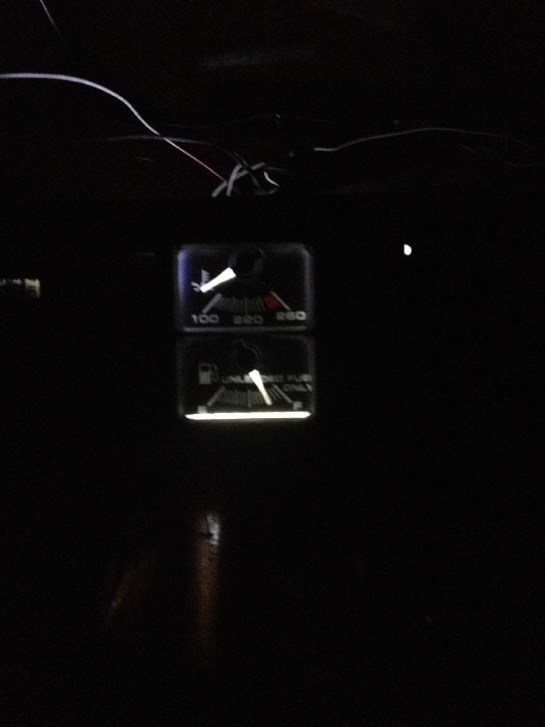
 Theres some light coming through the Temp and gas gauge, but I just need to replace the weatherstripping that came out when replacing the faces.