Pennock's Fiero Forum
  Technical Discussion & Questions
  The 3500 LX9 swap has begun! (Page 3)

Post New Topic  Post A Reply
Email This Page to Someone! | Printable Version

This topic is 4 pages long:  1   2   3   4 
Previous Page | Next Page
next newest topic | next oldest topic
The 3500 LX9 swap has begun! by masospaghetti
Started on: 02-22-2013 11:04 AM
Replies: 143 (9435 views)
Last post by: bcampbell on 02-17-2015 12:25 AM
masospaghetti
Member
Posts: 2477
From: Charlotte, NC USA
Registered: Dec 2009


Feedback score:    (10)
Leave feedback

Rate this member

Report this Post04-25-2013 07:01 AM Click Here to See the Profile for masospaghettiSend a Private Message to masospaghettiEdit/Delete MessageReply w/QuoteDirect Link to This Post
Rickady, did you have to relocate the holes where the brackets attach to the head?

I'm wondering if the 3100/3400 have the bolt pattern that the LX9 does, or if it matches the iron head 2.8.

I did get a new water pump, and I have an external crank position sensor I am using from British Car Conversions. There's no way to run DIS without one. I am not, however, using the cam sensor to run SFI (I heard the benefit is mainly at idle for emissions reasons).
IP: Logged
Rickady88GT
Member
Posts: 10648
From: Central CA
Registered: Dec 2002


Feedback score: N/A
Leave feedback


Total ratings: 202
Rate this member

Report this Post04-25-2013 11:40 AM Click Here to See the Profile for Rickady88GTSend a Private Message to Rickady88GTEdit/Delete MessageReply w/QuoteDirect Link to This Post
 
quote
Originally posted by masospaghetti:

Rickady, did you have to relocate the holes where the brackets attach to the head?


Yes, I welded them closed and redrilled new holes in the bracket.

 
quote
Originally posted by masospaghetti:

I'm wondering if the 3100/3400 have the bolt pattern that the LX9 does, or if it matches the iron head 2.8.

I did get a new water pump, and I have an external crank position sensor I am using from British Car Conversions. There's no way to run DIS without one. I am not, however, using the cam sensor to run SFI (I heard the benefit is mainly at idle for emissions reasons).


To make mine smog legal, I used all factory equipment. Ran great even after the swap over to manual. It was a 94 3100SFI. Keep in mind that it was no longer smog le3gal in CA after the manual swap.

IP: Logged
masospaghetti
Member
Posts: 2477
From: Charlotte, NC USA
Registered: Dec 2009


Feedback score:    (10)
Leave feedback

Rate this member

Report this Post05-06-2013 10:39 PM Click Here to See the Profile for masospaghettiSend a Private Message to masospaghettiEdit/Delete MessageReply w/QuoteDirect Link to This Post
I had to trim the crossover heat shield to clear the throttle body and the thermostat outlet:


You can see the tight clearance of the crossover here:


Brackets fabricated and painted, alternator mounted:


Had to trim the rear heat shield a bit near the alternator to give it clearance:


Coil packs mounted, I had to trim the coil pack bracket to clear the dogbone bracket. You can see the M10 stud I used to mount both:


Crossover finished installation:


IP: Logged
masospaghetti
Member
Posts: 2477
From: Charlotte, NC USA
Registered: Dec 2009


Feedback score:    (10)
Leave feedback

Rate this member

Report this Post05-07-2013 10:26 PM Click Here to See the Profile for masospaghettiSend a Private Message to masospaghettiEdit/Delete MessageReply w/QuoteDirect Link to This Post
2.8 engine sitting somewhat bare on the cradle, almost ready to be taken off:


(almost) completed accessory drive. Not sure if Rodney's idler will bolt up - I have a feeling it won't.

IP: Logged
masospaghetti
Member
Posts: 2477
From: Charlotte, NC USA
Registered: Dec 2009


Feedback score:    (10)
Leave feedback

Rate this member

Report this Post05-08-2013 04:45 PM Click Here to See the Profile for masospaghettiSend a Private Message to masospaghettiEdit/Delete MessageReply w/QuoteDirect Link to This Post
So...how important is that driveline absorber? The bolts to mount it on the block aren't there (so I'd have to rig something up), and the bushings are falling apart.

It seems like with a good dogbone with poly bushings, there wouldn't be much movement for the absorber to dampen.
IP: Logged
ericjon262
Member
Posts: 3082
From: everywhere.
Registered: Jan 2010


Feedback score:    (10)
Leave feedback


Total ratings: 66
Rate this member

Report this Post05-08-2013 05:14 PM Click Here to See the Profile for ericjon262Send a Private Message to ericjon262Edit/Delete MessageReply w/QuoteDirect Link to This Post
I played around with one on my swap, and decided it wouldn't be worth the effort to put it on.

------------------
we're in desperate need of a little more religion to nurse your god-like point of view...

Built not bought... Because bolt-ons don't.

https://www.fiero.nl/forum/Forum2/HTML/119122.html

IP: Logged
masospaghetti
Member
Posts: 2477
From: Charlotte, NC USA
Registered: Dec 2009


Feedback score:    (10)
Leave feedback

Rate this member

Report this Post05-10-2013 10:55 AM Click Here to See the Profile for masospaghettiSend a Private Message to masospaghettiEdit/Delete MessageReply w/QuoteDirect Link to This Post
Hmm, I will probably leave mine off then.

Do you know where I can find the wiring pinouts for the LX5 throttle body sensors (TPS, IAC) as well as the other sensors (3-pin coolant temp sensor, EGR, MAP)?

I messed up yesterday. Since Rodney's idler pulley picks up a hole in the alternator bracket that is no longer used, I could have simply tapped that hole in the alternator bracket and used a M12 bolt. I measured the hole wrong and ended up drilling it to 1/2". But at least the idler can still be used.

[This message has been edited by masospaghetti (edited 05-10-2013).]

IP: Logged
masospaghetti
Member
Posts: 2477
From: Charlotte, NC USA
Registered: Dec 2009


Feedback score:    (10)
Leave feedback

Rate this member

Report this Post05-11-2013 04:57 PM Click Here to See the Profile for masospaghettiSend a Private Message to masospaghettiEdit/Delete MessageReply w/QuoteDirect Link to This Post
I hit a significant hurdle today. Upon inspection I realized the input shaft sleeve (that the throwout bearing rides on) in my newly purchased Getrag tranny is cracked at the base about 1/3 the way around. I suppose I will have to split the case to repair it.


Finally got the 2.8 off the cradle.


IP: Logged
masospaghetti
Member
Posts: 2477
From: Charlotte, NC USA
Registered: Dec 2009


Feedback score:    (10)
Leave feedback

Rate this member

Report this Post05-18-2013 12:42 PM Click Here to See the Profile for masospaghettiSend a Private Message to masospaghettiEdit/Delete MessageReply w/QuoteDirect Link to This Post
Bump - looking for the LX5 throttle body IAC and TPS pinouts, as well as the coolant temp sensor (3-pin) pinout. Any help is appreciated.
IP: Logged
bcampbell
Member
Posts: 260
From: B.C., Canada
Registered: Nov 2011


Feedback score: (1)
Leave feedback

Rate this member

Report this Post05-18-2013 07:06 PM Click Here to See the Profile for bcampbellSend a Private Message to bcampbellEdit/Delete MessageReply w/QuoteDirect Link to This Post
I have all the pinouts you'll need on my laptop. I can email them to you if you PM me your address.
IP: Logged
masospaghetti
Member
Posts: 2477
From: Charlotte, NC USA
Registered: Dec 2009


Feedback score:    (10)
Leave feedback

Rate this member

Report this Post06-01-2013 12:02 AM Click Here to See the Profile for masospaghettiSend a Private Message to masospaghettiEdit/Delete MessageReply w/QuoteDirect Link to This Post
I've got to hand it to Rodney - his input bearing kit is top notch. I don't know how he's able to supply the tooling for the price he's charging for the kit, but I am very impressed with his product.

Successfully counterbored, drilled, tapped, and pressed in the new bearing and bolted the new sleeve down. Looks great in there:


I almost had the transmission ready to go, but the last bolt holding that detent assembly sheared off when I tried to tighten it. Strangely, the broken bolt easily came out of the hole. Had to make a trip to the hardware store to get a new bolt (M6-35mm, grade 10.9 this time).
IP: Logged
PFF
System Bot
masospaghetti
Member
Posts: 2477
From: Charlotte, NC USA
Registered: Dec 2009


Feedback score:    (10)
Leave feedback

Rate this member

Report this Post06-04-2013 11:32 PM Click Here to See the Profile for masospaghettiSend a Private Message to masospaghettiEdit/Delete MessageReply w/QuoteDirect Link to This Post
Marrying the engine and trans to the cradle:


Found out that the oil pan of the LX9 is not the same as the LNJ - The engine mount will fit the LNJ as-is, but the oil pan on the LX9 has to be trimmed away to fit for the front motor mount stud. Hopefully this won't cause any problems. Pre-trim:


Post-trim:


Also discovered that the crank trigger kit won't work without some modification. The alternator bracket is in the way. Haven't figured out what to do here yet.
IP: Logged
bcampbell
Member
Posts: 260
From: B.C., Canada
Registered: Nov 2011


Feedback score: (1)
Leave feedback

Rate this member

Report this Post06-04-2013 11:51 PM Click Here to See the Profile for bcampbellSend a Private Message to bcampbellEdit/Delete MessageReply w/QuoteDirect Link to This Post
I just trimmed the motor mount on mine instead of the oil pan. But yours should still be fine. Which part of the alternator mount hits the trigger?
IP: Logged
masospaghetti
Member
Posts: 2477
From: Charlotte, NC USA
Registered: Dec 2009


Feedback score:    (10)
Leave feedback

Rate this member

Report this Post06-05-2013 08:45 AM Click Here to See the Profile for masospaghettiSend a Private Message to masospaghettiEdit/Delete MessageReply w/QuoteDirect Link to This Post
The LX9 and LNJ have different shaped oil pans. Here is the LNJ from Bridgetown's thread:


Credit: KaijuSenso

I had to trim both the motor mount bracket and the oil pan to get it to fit. Without trimming the oil pan, the forward engine mount stud will touch the corner of the oil pan and it won't be possible to thread a nut onto the stud.

For the external crank trigger, it shares the top bolt hole of the engine mount bracket with the alternator bracket. I will either have to trim the alternator bracket down and slip the crank trigger bracket behind it (which means that that single bolt now holds my idler pulley, alternator bracket, crank trigger bracket, motor mount bracket, and threaded into the engine - not exactly elegant, or preferable) or I will have to mount it somewhere else and start essentially from scratch.

[This message has been edited by masospaghetti (edited 06-06-2013).]

IP: Logged
KaijuSenso
Member
Posts: 911
From: Westland, MI
Registered: Jan 2007


Feedback score: (1)
Leave feedback

Rate this member

Report this Post06-05-2013 11:07 PM Click Here to See the Profile for KaijuSensoSend a Private Message to KaijuSensoEdit/Delete MessageReply w/QuoteDirect Link to This Post
Hey that's my pic of the LNJ

Too bad the oil pans are not the same but good to know to help future swappers.
IP: Logged
masospaghetti
Member
Posts: 2477
From: Charlotte, NC USA
Registered: Dec 2009


Feedback score:    (10)
Leave feedback

Rate this member

Report this Post06-06-2013 09:25 AM Click Here to See the Profile for masospaghettiSend a Private Message to masospaghettiEdit/Delete MessageReply w/QuoteDirect Link to This Post
Also just for reference - I was working on my girlfriend's 04 Grand Am with the LA1 3400 last night and it appears to have the same oil pan configuration as the LX9.

Gave credit to you for the photo

[This message has been edited by masospaghetti (edited 06-06-2013).]

IP: Logged
bcampbell
Member
Posts: 260
From: B.C., Canada
Registered: Nov 2011


Feedback score: (1)
Leave feedback

Rate this member

Report this Post06-06-2013 09:57 AM Click Here to See the Profile for bcampbellSend a Private Message to bcampbellEdit/Delete MessageReply w/QuoteDirect Link to This Post
If you are able to make the trigger mount fit with the alt bracket and motor mount that's probably the best way to go. After all, the trigger mount won't see any stress.

I was able to get that nut on the motor mount stud without trimming the oil pan by tightening the bolt as I lowered the engine .
IP: Logged
masospaghetti
Member
Posts: 2477
From: Charlotte, NC USA
Registered: Dec 2009


Feedback score:    (10)
Leave feedback

Rate this member

Report this Post06-06-2013 01:02 PM Click Here to See the Profile for masospaghettiSend a Private Message to masospaghettiEdit/Delete MessageReply w/QuoteDirect Link to This Post
I was just concerned if that bolt had to be removed later for any reason, it would be difficult and annoying to reinstall it when there's so many parts. I would also have to modify the bracket to get it to fit.

I thought about installing the motor mount nut while lowering the engine. Probably would have been a better idea!

Question: Does it matter where the crank position sensor is located? Does it calibrate the timing based on the reference mark?

I'm debating whether to go with a trigger setup like this one below, instead of the kit I bought. It obviously positions the sensor differently though.

[This message has been edited by masospaghetti (edited 06-06-2013).]

IP: Logged
bcampbell
Member
Posts: 260
From: B.C., Canada
Registered: Nov 2011


Feedback score: (1)
Leave feedback

Rate this member

Report this Post06-06-2013 07:53 PM Click Here to See the Profile for bcampbellSend a Private Message to bcampbellEdit/Delete MessageReply w/QuoteDirect Link to This Post
I believe if you move the sensor you will also need to rotate the timing notches as well. But realistically, how often would you be removing the alternator bracket, motor mount bracket, or crank sensor mount? The alternator, motor mount, and crank sensor should all be serviceable without removing any of those.
IP: Logged
masospaghetti
Member
Posts: 2477
From: Charlotte, NC USA
Registered: Dec 2009


Feedback score:    (10)
Leave feedback

Rate this member

Report this Post06-07-2013 10:37 AM Click Here to See the Profile for masospaghettiSend a Private Message to masospaghettiEdit/Delete MessageReply w/QuoteDirect Link to This Post
You're right, it shouldn't be very often. Just bad design on my part to have so many parts there.

But I definitely don't want to get another balancer.
IP: Logged
Slowbuild
Member
Posts: 252
From: British Columbia
Registered: Nov 2009


Feedback score: N/A
Leave feedback

Rate this member

Report this Post06-07-2013 11:46 AM Click Here to See the Profile for SlowbuildSend a Private Message to SlowbuildEdit/Delete MessageReply w/QuoteDirect Link to This Post

On the crank sensor, you see the double notch on the balancer? that locates #1 cylinder for the coil pack electronics. It has to be in the correct relationship with #1 tdc:

http://www.megamanual.com/ms2/GM_DIS.htm

The above link explains it very well.


Chay
IP: Logged
PFF
System Bot
masospaghetti
Member
Posts: 2477
From: Charlotte, NC USA
Registered: Dec 2009


Feedback score:    (10)
Leave feedback

Rate this member

Report this Post06-07-2013 12:50 PM Click Here to See the Profile for masospaghettiSend a Private Message to masospaghettiEdit/Delete MessageReply w/QuoteDirect Link to This Post
But if the computer uses the 7th notch to locate TDC, then it shouldn't matter where the sensor is located, right?

Or am I looking at this wrong?
IP: Logged
Joseph Upson
Member
Posts: 4951
From:
Registered: Jan 2002


Feedback score: (2)
Leave feedback


Total ratings: 88
Rate this member

Report this Post06-07-2013 02:16 PM Click Here to See the Profile for Joseph UpsonSend a Private Message to Joseph UpsonEdit/Delete MessageReply w/QuoteDirect Link to This Post
 
quote
Originally posted by masospaghetti:

But if the computer uses the 7th notch to locate TDC, then it shouldn't matter where the sensor is located, right?

Or am I looking at this wrong?


Yes it does, the module has to sense the 7th notch with the appropriate piston at the right angle relative to top dead center, so you would have to relocate the 7x ring and sensor together relative to the crank in order for a move to work properly. It works like the distributor, install it 180 degrees off and you get a no start among other things, rotate the distributor cap and rotor/shaft 180 degrees and it works fine.

[This message has been edited by Joseph Upson (edited 06-07-2013).]

IP: Logged
masospaghetti
Member
Posts: 2477
From: Charlotte, NC USA
Registered: Dec 2009


Feedback score:    (10)
Leave feedback

Rate this member

Report this Post06-23-2013 10:12 PM Click Here to See the Profile for masospaghettiSend a Private Message to masospaghettiEdit/Delete MessageReply w/QuoteDirect Link to This Post
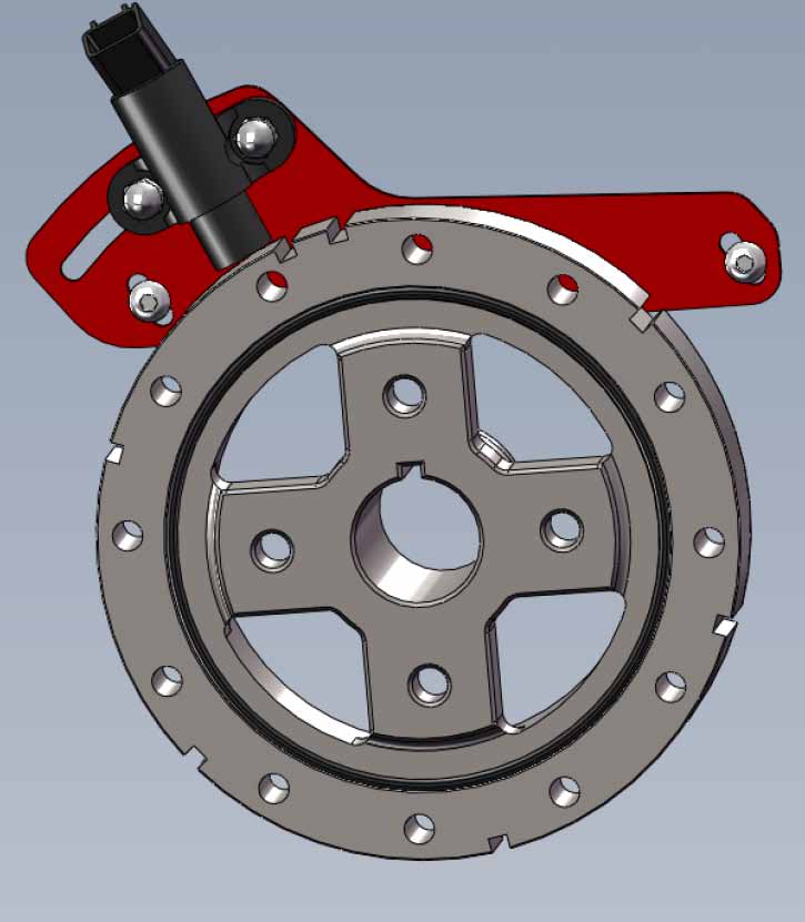
To prevent having all those parts share the same bolt holes, I welded a tab onto the motor mount to pick up two extra holes on the rear side of block - this way the mount won't shift and I won't need to block the engine if I have to take those two original bolts out to remove one of the brackets, or to change the crank sensor. The crank sensor bracket is mounted here too:


I went ahead and mounted the crank sensor bracket. I had to hack up my alternator bracket a bit to get it to fit - more on that later. I am taking the brackets into work tomorrow, hopefully they can stress relieve the welds I made previously on my alternator and air conditioning brackets in one of their ovens - I don't want these cracking later.

[This message has been edited by masospaghetti (edited 06-23-2013).]

IP: Logged
Darth Fiero
Member
Posts: 5921
From: Waterloo, Indiana
Registered: Oct 2002


Feedback score: (5)
Leave feedback


Total ratings: 361
Rate this member

Report this Post06-24-2013 10:59 AM Click Here to See the Profile for Darth FieroClick Here to visit Darth Fiero's HomePageSend a Private Message to Darth FieroEdit/Delete MessageReply w/QuoteDirect Link to This Post
 
quote
Originally posted by masospaghetti:

But if the computer uses the 7th notch to locate TDC, then it shouldn't matter where the sensor is located, right?

Or am I looking at this wrong?


Actually, the 1227730 computer doesn't care where TDC #1 cylinder is NOR is it capable of determing that. It is the ignition module in these applications that determines where TDC #1 or #4 cylinder is by "the 7th notch" on the crank sensor reluctor wheel. The ignition module uses the 7th notch to properly "align" firing of the coils with TDC #1 & #4 cylinders, and once that happens for the 1st time during engine cranking, it begins firing the coils and sending reference pulses to the ECM. This means it can take up to 1 full crankshaft rotation on these systems before the coils start firing. The ignition module can't know if the engine is at TDC for cylinder #1 or cylinder #4 because it doesn't know cam position (and neither does the 7730 ECM).

And yes, it DOES matter where the crank position sensor angle is located in relation to the 7th notch in relation to actual TDC for cylinders 1 & 4. This needs to be set up to match what it was stock on GM 60 deg V6's with generation 1 DIS systems.

SFI 60 deg V6 systems use the cam position sensor to determine TDC #1 cylinder position along with both the 7x crank sensor input from the ignition module and the 24x crank sensor feed directly (in case you were wondering).

------------------
OVERKILL IS UNDERRATED

Custom GM OBD1 & OBD2 Tuning | Engine Conversions & more | www.gmtuners.com

[This message has been edited by Darth Fiero (edited 06-24-2013).]

IP: Logged
masospaghetti
Member
Posts: 2477
From: Charlotte, NC USA
Registered: Dec 2009


Feedback score:    (10)
Leave feedback

Rate this member

Report this Post06-24-2013 12:08 PM Click Here to See the Profile for masospaghettiSend a Private Message to masospaghettiEdit/Delete MessageReply w/QuoteDirect Link to This Post
Great info, thanks for sharing.

If I haven't said it already, thanks to everyone who's contributed information to my swap.
IP: Logged
masospaghetti
Member
Posts: 2477
From: Charlotte, NC USA
Registered: Dec 2009


Feedback score:    (10)
Leave feedback

Rate this member

Report this Post06-24-2013 12:47 PM Click Here to See the Profile for masospaghettiSend a Private Message to masospaghettiEdit/Delete MessageReply w/QuoteDirect Link to This Post

masospaghetti

2477 posts
Member since Dec 2009
Question: What size AN adapters will fit the factory fuel line fittings?

I was looking for an AN-to-barb fitting so I can use standard fuel injection hose.
IP: Logged
bcampbell
Member
Posts: 260
From: B.C., Canada
Registered: Nov 2011


Feedback score: (1)
Leave feedback

Rate this member

Report this Post06-24-2013 01:04 PM Click Here to See the Profile for bcampbellSend a Private Message to bcampbellEdit/Delete MessageReply w/QuoteDirect Link to This Post
I believe the OEM fittings are 14mmx1.5 o-ring and 16mmx1.5 o-ring. The 3400 rail should have two quick-disconnect fittings (3/8 and 5/16ths). Russell makes fittings for all of the above.
IP: Logged
masospaghetti
Member
Posts: 2477
From: Charlotte, NC USA
Registered: Dec 2009


Feedback score:    (10)
Leave feedback

Rate this member

Report this Post06-24-2013 01:38 PM Click Here to See the Profile for masospaghettiSend a Private Message to masospaghettiEdit/Delete MessageReply w/QuoteDirect Link to This Post
Thanks bcampbell.

So I was buying exhaust piping and realized I should have asked this a lot earlier - will the exhaust i'm putting together (exiting the rear manifold) require cutting out the trunk?

EDIT: Also will a standard ball flange fit the 3400 manifolds or does GM use a special type?

EDIT AGAIN: Just bought exhaust parts to fab up the exhaust. Hope it clears the trunk. Also it appears the flange is a standard 2-bolt using Walker gasket 31602, a non-ball flange type.

[This message has been edited by masospaghetti (edited 06-25-2013).]

IP: Logged
masospaghetti
Member
Posts: 2477
From: Charlotte, NC USA
Registered: Dec 2009


Feedback score:    (10)
Leave feedback

Rate this member

Report this Post06-26-2013 09:48 PM Click Here to See the Profile for masospaghettiSend a Private Message to masospaghettiEdit/Delete MessageReply w/QuoteDirect Link to This Post
The wiring begins.


Starter connections bolt right in. Block grounds on the driver's side of the engine (the 4 small ones) had to be relocated to avoid the hot exhaust manifold. The pinouts provided by bcampbell and Sinister Performance made a lot of the connections a snap - MAP sensor uses the same three wires but different connector; DIS connectors basically use the old distributor and coil connections; new coolant temperature sensor combines the old sensor/sender into a single unit and the wires seem to connect right up.

IP: Logged
masospaghetti
Member
Posts: 2477
From: Charlotte, NC USA
Registered: Dec 2009


Feedback score:    (10)
Leave feedback

Rate this member

Report this Post06-27-2013 01:03 PM Click Here to See the Profile for masospaghettiSend a Private Message to masospaghettiEdit/Delete MessageReply w/QuoteDirect Link to This Post
It appears that the linear-type EGR valve from the 3500 will not communicate properly with the 7730 ECM, which expects a 3-solenoid digital EGR.

This appears to be the solution, an adapter plate that allows use of the 3-solenoid valve on the 3500 plenum. Hopefully it fits.

IP: Logged
PFF
System Bot
masospaghetti
Member
Posts: 2477
From: Charlotte, NC USA
Registered: Dec 2009


Feedback score:    (10)
Leave feedback

Rate this member

Report this Post06-30-2013 08:39 PM Click Here to See the Profile for masospaghettiSend a Private Message to masospaghettiEdit/Delete MessageReply w/QuoteDirect Link to This Post
Need help: The new coolant temperature sensor has 3 wires - ECM signal, ground, and gauge. I assume the "gauge" lead goes to the temperature gauge and not the dummy light. How do I wire up both the dummy light and temperature gauge?
IP: Logged
Joseph Upson
Member
Posts: 4951
From:
Registered: Jan 2002


Feedback score: (2)
Leave feedback


Total ratings: 88
Rate this member

Report this Post07-01-2013 08:14 AM Click Here to See the Profile for Joseph UpsonSend a Private Message to Joseph UpsonEdit/Delete MessageReply w/QuoteDirect Link to This Post
 
quote
Originally posted by masospaghetti:
Need help: The new coolant temperature sensor has 3 wires - ECM signal, ground, and gauge. I assume the "gauge" lead goes to the temperature gauge and not the dummy light. How do I wire up both the dummy light and temperature gauge?


You have to choose. You have a need for an input to the ECM, a must for either a temp gauge reading or hot light signal and a want for a display of which ever of the last two is left over which I'm sure is the hot light.

I drilled and tapped the coolant crossover for the the 3900 and installed the stock 2.8L sensor and plugged the stock harness into it with only the hot light lead connected. The ECM and gauge feed off the 3 terminal sensor.

You can either do the same at the thermostat housing if there is room, or you can connect the hot light signal wire into the Fan # 2 relay control terminal and set the settings to the temp you want the ecm to warn you that the motor is hot, I'd say about 250 deg would be a good set point, and go with that unless you intend to use a second fan provided you have logic for a second fan in the code mask you are using.
IP: Logged
masospaghetti
Member
Posts: 2477
From: Charlotte, NC USA
Registered: Dec 2009


Feedback score:    (10)
Leave feedback

Rate this member

Report this Post07-01-2013 08:59 AM Click Here to See the Profile for masospaghettiSend a Private Message to masospaghettiEdit/Delete MessageReply w/QuoteDirect Link to This Post
 
quote
Originally posted by Joseph Upson:
...you can connect the hot light signal wire into the Fan # 2 relay control terminal and set the settings to the temp you want the ecm to warn you that the motor is hot, I'd say about 250 deg would be a good set point, and go with that unless you intend to use a second fan provided you have logic for a second fan in the code mask you are using.


That's a great idea. I intended to only use the standard Fiero single stage fan so this sounds like the best way to go. Thanks for the help.
IP: Logged
masospaghetti
Member
Posts: 2477
From: Charlotte, NC USA
Registered: Dec 2009


Feedback score:    (10)
Leave feedback

Rate this member

Report this Post07-01-2013 11:47 PM Click Here to See the Profile for masospaghettiSend a Private Message to masospaghettiEdit/Delete MessageReply w/QuoteDirect Link to This Post

masospaghetti

2477 posts
Member since Dec 2009
Starting to look like an actual engine...


Got a lot of wiring done, all that's left is EGR, EVAP, and some secondary lines that are added for the 7730 computer. Also got my old shifter out, working on putting in the 5-speed shifter.
IP: Logged
masospaghetti
Member
Posts: 2477
From: Charlotte, NC USA
Registered: Dec 2009


Feedback score:    (10)
Leave feedback

Rate this member

Report this Post07-05-2013 11:55 AM Click Here to See the Profile for masospaghettiSend a Private Message to masospaghettiEdit/Delete MessageReply w/QuoteDirect Link to This Post
Will the standard 2.8 oil filter work on the LX9? it screws on and physically fits with no problems.

Got a weatherpack connector kit so I can make my own OEM-style connections, instead of those bullet or spade connections. This is basically what I got although the actual kit I purchased is no longer available:

Kit

Been modifying my ECM tray to get it to fit - either mine wasn't a real 87-88 tray, or they aren't a drop in replacement as I thought. Been reassembling the interior a bit.

I also made the mistake of removing that little climate mode actuator behind the radio. It had been making some noise although it never failed, so I thought I could remove and clean it. WRONG - it has a ton of stuff attached to it! I put it back after I realized my mistake. Hopefully it still works.

[This message has been edited by masospaghetti (edited 07-05-2013).]

IP: Logged
bcampbell
Member
Posts: 260
From: B.C., Canada
Registered: Nov 2011


Feedback score: (1)
Leave feedback

Rate this member

Report this Post07-05-2013 07:35 PM Click Here to See the Profile for bcampbellSend a Private Message to bcampbellEdit/Delete MessageReply w/QuoteDirect Link to This Post
You need the 4 cylinder tray to work with the 7730 I think. Although I just modified the V6 tray to work in my swap.
IP: Logged
masospaghetti
Member
Posts: 2477
From: Charlotte, NC USA
Registered: Dec 2009


Feedback score:    (10)
Leave feedback

Rate this member

Report this Post07-12-2013 10:07 AM Click Here to See the Profile for masospaghettiSend a Private Message to masospaghettiEdit/Delete MessageReply w/QuoteDirect Link to This Post
Any suggestions on cable routing for the cruise control?

I see that the 3400 bracket should work for the throttle cable.
IP: Logged
masospaghetti
Member
Posts: 2477
From: Charlotte, NC USA
Registered: Dec 2009


Feedback score:    (10)
Leave feedback

Rate this member

Report this Post07-13-2013 10:36 PM Click Here to See the Profile for masospaghettiSend a Private Message to masospaghettiEdit/Delete MessageReply w/QuoteDirect Link to This Post
Still have no idea on the throttle cable, how have others gotten it to fit the new throttle body? Any help is appreciated!

However, I did accomplish a big psychological goal today and got the engine installed in the compartment, no issues with clearances. Still have a couple connections to make but everything has a home.


IP: Logged
bcampbell
Member
Posts: 260
From: B.C., Canada
Registered: Nov 2011


Feedback score: (1)
Leave feedback

Rate this member

Report this Post07-13-2013 10:41 PM Click Here to See the Profile for bcampbellSend a Private Message to bcampbellEdit/Delete MessageReply w/QuoteDirect Link to This Post
Do you have the LX5 throttle cable bracket? That's what I used on mine with the stock throttle cable.
IP: Logged
Previous Page | Next Page

This topic is 4 pages long:  1   2   3   4 
next newest topic | next oldest topic

All times are ET (US)

Post New Topic  Post A Reply
Hop to:

Contact Us | Back To Main Page

Advertizing on PFF | Fiero Parts Vendors
PFF Merchandise | Fiero Gallery | Ogre's Cave
Real-Time Chat | Fiero Related Auctions on eBay


Copyright (c) 1999, C. Pennock