But anyway, awesome stuff! I gotta say, that Duke had a weird looking pressure plate, never seen one like that before. I suggest saving the flywheel, Duke flywheels are getting really hard to find, so I'm sure someone will need one sooner or later here on this Forum.
[This message has been edited by mattwa (edited 05-05-2012).]
But anyway, awesome stuff! I gotta say, that Duke had a weird looking pressure plate, never seen one like that before. I suggest saving the flywheel, Duke flywheels are getting really hard to find, so I'm sure someone will need one sooner or later here on this Forum.
I am saving the flywheel but for different reasons. I had the holes pluged and redrilled to match the 4.9 crank by a friend. He also has a lathe to make the centering ring so all she cost is around $70 for a professional resurfacing. Yeah I know they sell them to fit new but I couldn't resist the lure of another project to save a few bucks. I can't say I"m 100% confident but time will tell. If I had to do it again, with what it cost and all the running around, I'd just order a new proper one. That being said, if there are any problems with it, I'll toss it.
I am saving the flywheel but for different reasons. I had the holes pluged and redrilled to match the 4.9 crank by a friend. He also has a lathe to make the centering ring so all she cost is around $70 for a professional resurfacing. Yeah I know they sell them to fit new but I couldn't resist the lure of another project to save a few bucks. I can't say I"m 100% confident but time will tell. If I had to do it again, with what it cost and all the running around, I'd just order a new proper one. That being said, if there are any problems with it, I'll toss it.
Chances are the Isuzu will break before the flywheel.
On my duke this oil sender failed and became a hole in the side of the block. The only thing keeping the oil in was the electrical connector.
Finding out that that was the cause was fun since I could not even see it in the car, used a video camera hooked to an lcd screen in the end to see under there. Getting out out was a whole other story, had to make a special socket just to fit it. What a pain.
I guess you won;t be having that problem though any more!
Yeah, I couldn't see where the smoke was coming from until it erupted in flames. Then it was easy.
The silver lining to this cloud is that it proved an excellent justification for replacing the fire hazard with a much more reliable V8. Or at least that's the way I explained it to the wife.
The silver lining to this cloud is that it proved an excellent justification for replacing the fire hazard with a much more reliable V8. Or at least that's the way I explained it to the wife.
Here you can see the difference in thickness b/w the old disk and new centerforce clutch disk. Not much. I hate replacing a good part but I don't have much of a choice if I want to transfer all that torque to the isuzu in order to break it.
Here's the freshly machined flywheel ready to be plugged and redrilled to match the 4.9. I chose this route only because part of this whole swap is to save money and use what I have. Time will tell if this was the right decision.
The 2.5 flywheel bolts are different than the 4.9 flexplate bolts. The thread on the 4.9 are finer than the course threads of the 2.5. The 4.9 bolts are considerably shorter because they only have to go through a thin flexplate and not a thick flywheel. For t his reason you need the bolts for the 2.8 v6 which are the same size, just longer.
Here the bolts are sticking out the backside of the flywheel. This shows how much thread will penetrate the 4.9 crankshaft. I'm sure the 4.9 bolts would work but I'll follow the crowd on this one and use the 2.8 bolts.
I didn't get a pic of the flywheel drilled and plugged before I bolted it in place with locktite. I did however use this neat washer that was on the 4.9 flexplate. My intentions are that if any of the plugs decide to work their way out, this will hold them in for sure. I checked clearances first and no problems presented themselves...yet.
I don't have a clutch disk centering tool and didn't feel like driving to buy one, so I improvized.
The center ring in the flywheel is a different inner diameter than the splined clutch disk so there is a step made of wrapped masking tape.
Pressure plate torqued down and all worked well.
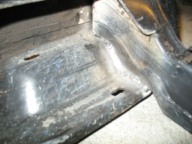
With the tranny off and engine removed, the cradle was time consumingly cleaned. Scrapers, screw drivers, Varsal, rags, wire brushes, and a vacuum. Then it gets wiped down with laquer thinner to remove all traces of oil and grease. Very difficult to get into all those nooks and crannies.
I don't like the cradle bracket that goes under the oil pan to mount the engine. I plan on spacing out the engine mounts for better torque stability so this bracket gets removed. I also like it's absence in the event I ever need to pull the oil pan.
Cleaned up for future coating. The whole cradle was covered in welding spatter. Small balls of steel that shoot off during welding that stick to the surrounding surface. A chisel, hammer, and many hours to knock them all off...well, almost all. You always miss a few!
[This message has been edited by Reallybig (edited 05-08-2012).]
No problems with the clutch disk hub hitting the flywheel bolts?
I had seen that some people had clearance problems with their clutch disk and the bolt heads so I made sure to check for proper clearance. If you look at the picture of the Centerforce clutch disk flywheel side, you'll see a machined outer edge to the splined female coupler that considerably reduces the amount of material to interfere with the bolt heads. No problemo!
With the cradle out of the way and the 2.5 off to the side, I felt like mating the tranny to the engine and dealing with the starter clearance issue. Here I used long bolts to position the tranny and mark out where to remove some aluminum bellhousing.
I know that the Allante starter is a better way to go but it isn't that easy to find, costs more money, and I had already rebuilt this starter before I had ever heard of the other options. Using a die grinder, a tungsten carbide bit, and lots of time, I removed some material, checked the fit, move the tranny, remove material, check the fit, move the tranny, remove material etc. 20 or 30 repetitions later, this is what I have as the final result:
With the engine and tranny united, it's time to mock up the engine on the cradle. Using that notch I made earlier with the 2.5 in factory location, I locate the center of the 4.9 crankshaft bolt while the tranny sits on it's factory mounts in their factory locations.
I leveled the cradle on the floor with washers as shims as a uniform starting point. Oddly enough the top of the tranny didn't come out perfectly level as I thought it would. Does this mean that the tranny mounts are not correct? Brackets bent? Or is this just the way it's supposed to be? It was working when I pulled it out, so why mess with success?
Now I'm going to complicate things...Dropping the engine and tranny 1/2" for added clearance on top. I didn't want an issue with the deck lid hinge or the alternator in the stock location causing interference so I'm hoping this will be enough to prevent issues. Checking all the details leaves 1/2" as the max it can be lowered without causing the CV axle assembly from hitting the cradle. (same as I had read in another swap) First I'll use the level to mark a vertical line on both sides of the tranny brackets. This will give me a simple way to lower the transmission with its complicatedly bent mounts. Using a zip cut disk, I sliced them apart and marked their relocation. Measure 2,3,4 times...cut once! Cut, tacked, and welded to lower;
Small pieces welded in to fill the gaps created by shifting the two parts
With the transmission lowered 1/2", I can now design my engine mounts to lower the distance to the center of the crankshaft bolt by 1/2". All the while I am doing this, the engine is suspended from the hoist I used to lift the car off the cradle assembly. It makes it easy to just lightly push the engine aside when needed. For safety, the cradle is sitting on the floor and the engine just inches above that.
[This message has been edited by Reallybig (edited 05-09-2012).]
It's always good to lower the powertrain as much as possible, however it wasn't necessary for clearance of the alternator, decklid doesn't need to be cut for it.
Looks really good though so far, good work
[This message has been edited by mattwa (edited 05-09-2012).]
Thanks for the support! I though I read somewhere the alternator gets in the way. If it doesn't, that's just a bonus! The main reason though is to clear the deck hinge while using the undented valve cover on the back. The hinge support is trimmed up to the lowest of the two bolts, but lowering the drivetrain really makes a difference in clearance.
Yea it doesn't hit just sitting there, but any movement on stock mounts the torsion bar will hit the alternator, just look at mine when my first 2nd engine mount broke. But now it's mounted quite solid.
[This message has been edited by mattwa (edited 05-09-2012).]
I'm assuming by "torsion bar" you are referring to the decklid support torsion bars. It's been so long since I had the decklid on I don't even remember where they went! That being said, they won't be going back on. I don't believe they would fit back on with the aluminum firewall panel in the way. I planned from the start to get rid of the torsion bar set up in favor of a gas strut. Which is better?...both have their pro's and con's. I like the idea of the lid opening with that authoritative smooth motion to a dead stop instead of a spring loaded bounce! The PS deck lid hinge stop cable is broken any how so this project will provide another means of stopping. I was thinking of going with just one strut on the DS. Does it make a big difference with 2 or will one do the job just fine?
I personally like two, however normally you can't run one on the passenger side because of the alternator, but I'm not sure if that 1/2" will be enough or not.
I personally like two, however normally you can't run one on the passenger side because of the alternator, but I'm not sure if that 1/2" will be enough or not.
I would recommend two otherwise the decklid will lift and close crooked depending on where you push down. I ended up using just 1 and keeping the worn out tension bar.
Yes! All your photos ARE inspiring! When I get the time (famous last words) I'd love to take my 85 SE down to every last nut and bolt. I love your aluminum "reflector" in the engine compartment. As far as a gasket for the base of the air filter can, I stumbled upon a great solution. I was at the hardware store looking at their selection of rubber gaskets, but none were close to the size needed. Then, I saw a replacement strainer for a kitchen sink. It came with a rubber gasket about 2-3mm thick, all for about $7. The black chloroprene gasket is very durable and an exact fit! So, with a sink strainer gasket installed, you have almost literally included everything WITH "the kitchen sink".
Yes! All your photos ARE inspiring! When I get the time (famous last words) I'd love to take my 85 SE down to every last nut and bolt. I love your aluminum "reflector" in the engine compartment. As far as a gasket for the base of the air filter can, I stumbled upon a great solution. I was at the hardware store looking at their selection of rubber gaskets, but none were close to the size needed. Then, I saw a replacement strainer for a kitchen sink. It came with a rubber gasket about 2-3mm thick, all for about $7. The black chloroprene gasket is very durable and an exact fit! So, with a sink strainer gasket installed, you have almost literally included everything WITH "the kitchen sink".
Thanks! It's off to Homedepot! As much as I would like to fully restore this car, I'll try to complete one project at a time. I'm hoping this way I won't lose interest or become frustrated. One project, then drive for a while. Next project etc.... Just that this is one BIG project full of little projects like the battery relocation...
Back from a few days in Vancouver BC for the kid's Western Canadian Taekwon-Do Tournament (3 golds, 1 silver) and visiting family so it's time to post a few more pics.
In order to use the aluminum engine bracket that came on my 4.9 I built a braket to bolt to the bracket. This way the mount would be level with the cradle and it just made me more comfortable with the setup.
And here's the bracket welded to the cradle that the mount will sit on. Not happy with the final look as it doesn't appear stock but what's done is done. The tan colored stuff is the result of using flux cored wire in my welder. Just a thin layer of slag and smoke that comes off easliy with a wire wheel on a grinder.
And the bracket for the rear side of the 4.9 that is welded to the cradle. This one ends up looking a little more stock in the end.
You get the basic idea from this shot. It should clear the axel during it's suspension travel.
I wanted to use all 4 bolts on this side for my own personal peace of mind as I am not truly confident in the aluminum block strength and only 2 or 3 bolts. Of course this bracket is custom too. The whole set up was required b/c I removed the original mounting under the oil pan...now the exhaust can go straight to the back.
Next I gotta get the suspension ready for powder coating with the cradle and tranny brackets. I'll show how I removed all the bushings from the trailing arms without burning the rubber...and in less time than it would take to set up an oxy-ace torch. (how long it takes me that is)
[This message has been edited by Reallybig (edited 05-16-2012).]
I just used a propane torch and heated the outside sleeve (or the link itself when there is no sleeve) of the rubber bushing, and when it started smoking a bit I just pressed it out with a C-clamp and some homemade pieces.
88 rear suspension bushing press out easily with sockets and a vise.
No heating required.
That's where I'm going with this! I just have not seen anyone suggest it or show pics. Figured I'd do a step by step to show how easy it is. Every time I see it done here someones firing up a torch. At least if the bushings are pressed out with sockets they could be reused if needed.
This thread brings back lots of memories of the last 4.9/Isuzu swap I did in an 88. I sectioned the transmission mounts and made a very similar rear engine mount. I was able to get the engine centerline to be just under 8" from the bottom of the 88 cradle with a little work. I hope you checked for axle clearance between the rear engine mount and the axle, as it will be very close. Here is the clearance on mine:
If you would like more pictures of this swap, I can PM them to you... this car never got a build thread, but I have lots of pictures of the swap.
Also, while you have the welder out, run a weld bead on the inside of the rear transmission mount pocket. The factory weld is prone to cracking and allowing the bottom side of rear cradle crossmember to break free.
[This message has been edited by fieroguru (edited 05-16-2012).]
This thread brings back lots of memories of the last 4.9/Isuzu swap I did in an 88. I sectioned the transmission mounts and made a very similar rear engine mount. I was able to get the engine centerline to be just under 8" from the bottom of the 88 cradle with a little work. I hope you checked for axle clearance between the rear engine mount and the axle, as it will be very close.
If you would like more pictures of this swap, I can PM them to you... this car never got a build thread, but I have lots of pictures of the swap.
Also, while you have the welder out, run a weld bead on the inside of the rear transmission mount pocket. The factory weld is prone to cracking and allowing the bottom side of rear cradle crossmember to break free.
I hope the memories brought back are good ones! I checked for clearance and it looks very similar to yours but things seem to change b/w mock up and final install...here's hoping for the best!
Any pics you think are of help would be greatly appreciated. Feel free to stick them in this thread where and whenever you feel they fit. To me, part of the point of "threading" is to provide others with our personal experiences so they themselves can pick up on details for their own projects, and reject those that prove ridiculous.
I'm not sure of the exact location you are referring to on the cradle but I'll give the area a good inspection to assess condition. Thanks for the heads up!
Ok. Here I go with the the technique I used to remove 88 rear link arm bushings.
First find a socket that matches or is slightly smaller than the inner steel sleeve, bushing, spacer, what ever you want to call it. I clamp it in a bench top vice like so;
Pull the link arm toward you to expose the inner rubber/sleeve surface so you can shoot some wd40 in there, and then push it in away to expose the other side of the sleeve and rubber inner bushing for a shot of wd40. The vice should be quite tight to prevent things from popping out and flying in those hard to reach places. It didn't happen to me but I can see how it easily could. The hardest part is lining up the socket and steel sleeve yourself while trying to tighten the vice. I did it all myself but a second set of hands would have made things easier. Word of advice; let the other person put their fingers in the pinch areas as to save yourself from being injured.
I'm using a socket for a 1/2" ratchet as mine are longer than the sockets for my 3/8" ratchet but not too long to fit in the vice as my 3/8" deep sockets. If none of that made sense to you...you need more sockets!
Here you can see how much deflection the rubber bushings can have. I would imagine that throughout the entire suspension it can add up to some serious movement!
Once you have 2 quick shots of wd40 b/w the rubber bushing and the steel sleeve, use the link arm To rotate the rubber bushing around the sleeve to destribute the wd40 completely. While moving the link arm back and forth, pull gently toward you and the rubber bushing will stay in the link arm but walk off the sleeve onto the socket.
Take the link arm with the socket and sleeve out of the vice and pull them out with a pair of pliers or channel locks. They are lubed and come out easily. A quick shot of the measurements I was dealing with b/w my vice, socket and steel sleeve.
With the larger link arms picture above, I didn't have a socket large enough to fit around the rubber bushing if it were to be pressed out. I imagine most people wouldn't have sockets that large so I'll describe how I got them out...I guess I need some more sockets!
I put the arm in the vice and stuck small Phillips screwdriver between the bushing and arm.
I then shot some wd40 down the sides of the screw driver and wiggled it back and forth to distribute the wd40 b/w the bushing and link arm. I did this 3 times around each bushing 120 degrees apart.
With a thin layer of wd40 now surrounding the rubber bushing, after the last screw driver wiggle I grabbed the handle and the lower end of the screw driver and pulled it all the way around the circumference of the bushing while it was till inside the link arm end. This made sure the bushing was fully lubed and any seal b/w the bushing and arm was now broken.
Using a larger screw driver (but a number of other tools would work too) I just pushed the bushing out!
I know that it may seem like a lot of work but when you have all link arms on your work bench and a set of sockets, wd40 and a few screw drivers, it goes really fast...and with no smell of burnt rubber. The added bonus of retaining the bushings if they are in good shape is worth this effort. You could sell them in the mall or put them back in the link arms when you get older and are tired of the rough ride some people complain they get from Poly bushings.
[This message has been edited by Reallybig (edited 05-19-2012).]
The bushings would be a real treat to reinstall - once they are out - toss 'em.
You are making that really hard - use a socket that is just a little smaller than the bushing on the rubber side and a piece of exhaust tubing that fits the metal loop and press them out. Whats with the lube and screwdriver?
EDIT: I changed the wording in the above post to hopefully sound better and make more sense. Also replaced the word "lube" with wd40 for you.
I know it sounds complicated and probably takes more time to read than do, but it worked! I figured that the rubber bushings would be easier to take out if the inner sleeves were removed first so that's the way I did it. It went real fast so I didn't entertain other options. Anyway I still figure it is faster than burning them out. Besides, the additional hastle and lube was because I didn't want to damage them in case I had to put them back. I didn't have a socket as large as the metal loop on the long links and didn't think of using exhaust pipe. I'm not sure if that setup would fit in my bench vice anyhow. I guess the goal was to get the job done as easily as I could with what I had. Next time I'll try your method...it does sound easier!
[This message has been edited by Reallybig (edited 05-19-2012).]
Some more pics of removing the bushings from the two shorter link arms. I remove the inner sleeve and then the rubber bushing. This way if I needed to reuse the bushings for any reason I could put them back. (I'd push the rubber bushing in first and then the inner sleeve) Using wd40 made sure they weren't damaged while removing the rubber.
pushing out the rubber
I thought I'd give simplicity a try on the adjustable links They came out easily using olejoedad's method of just sockets and no oil...thanks!
With the transmission mounted to the engine, I took the bellhousing dust shield and modified it to fit the 4.9.
It now fits snugly around the oil pan and block shape but I need to fill in the area where the 2.5 starter went through.
A piece of thin sheetmetal cut and ready to tack in place.
Ground the welds smooth (as possible) and gave it a coat of paint. I added a drainage hole at the bottom. Not sure it it's really needed but I figure it couldn't hurt.
A few pics I missed during mockup for the engine mounts. Don't worry, I do have plans for the rust on the cradle.
I thought with the cradle level, the engine would be too...not so here. Maybe it's just the bellhousing? I went with it anyhow.
Suspension components back from powder coating
There's one wierd bracket there... it's a modified front transmission mount for the isuzu.
I couldn't find a stock replacement locally and didn't want to order one online.
I took some measurements, cut the stock tranny mount, made a base plate, and zapped them together.
Now if I ever need to replace it again, I can just use the same mount that is supporting the engine as well!
Cradle coated too. I tell ya, this stuff is strong! Where a spraycan job would chip when bumped with a screwdriver, this stuff you can beat on and just mark it up a bit!
Here are some pics of the finished custom cradle mounts. Starting with the rear one.
On the front engine mount bracket I capped it off with a piece of bent plate to make sure that the welds wouldn't crack down the front. I just felt more comfortable knowing that the bracket encompassed three sides of the cradle. Probably over thinking things here but I'm happy with it!
The bracket sits further away from the cradle than most you see. It's because I used the Aluminum bracket that came with my engine instead of the stamped metal (more common?) one.
[This message has been edited by Reallybig (edited 05-22-2012).]


 But now it's mounted quite solid.