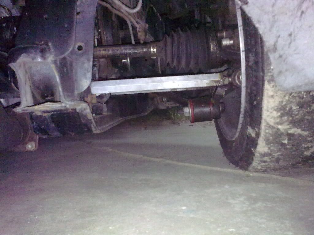
Here's the effect of raising the inboard mounting points of the lower control arms. I think. I think the previous owner raised them. Right now the cradle ride height is 4" on 15" slicks with a 22.9" diameter.
just noticed this. interesting that your axle seems to be going uphill toward the engine even after lowering. how much farther off the ground is the bottom of your trans compared to the bottom of the cradle? do you have a pic of the other side to show us how close those mounts are to the trans? i know i have no room to move mine up at all. thanks
For those interested, I posted a three-view drawing of the '88 front upper control arm in my build thread in the construction zone. Rather than duplicate the drawings in both threads, I'll post notices in this thread when I add individual drawings to my build thread. I will however post the completed assembly in here once it's done and analyzed.
It's the angle of the photo that is deceiving. Both the lower adjustable links and the axle are angled down to the transmission.
The axle clears the lower control links on the driver side by about 3/4". It looks like the cradle has been lowered about 1". Right now the cradle ride height is about 3.5". The transmission pan is about flush with the bottom of the cradle. (Actually it's below the cradle as the builder added an extension on the pan to increase the oil capacity.)
Another update: I completed the three-view drawing of the 88 front lower control arm and posted it in my build thread (link is posted by 88GTS above). Next up is the knuckle.
Another update: I recently completed the three-view drawings of the '88 front knuckle and bearing assembly and posted them in my build thread above. I should have the complete front suspension drawing package finished up soon, and again, I will post the analysis here.
thanks again for sharing blooz! cant wait to see the rest!
i have been researching tall upper ball joints today. it is common in s10 and early camaros to get a 1/2" taller joint. how much would this help? the gains in those cars were very significant, and there were ways to tune out bumpsteer. i could not find any info on tapers, but maybe the knuckles could be reamed to fit? http://www.proforged.com/pa...all-Upper-Ball-Joint such as these
It is common in s10 and early camaros to get a 1/2" taller joint. how much would this help?
I could take an educated guess at the impact of installing taller ball joints, but then the whole purpose of doing these drawings is to have a model to see first-hand what happens.
On that note, I keep chugging away at these component drawings for the front suspension. The latest ones were added to my build thread today: upper and lower ball joints, and the front uper control arm mount. All that's left is the tie rod now.
Before I went though the trouble of designing the double A-arm I wanted to try to solve the camber issue using the existing strut tower as this would significantly reduce the cost and build time. As it turns out I had no problem redesigning the lower control arm and engine cradle to accommodate my desired camber gains.
I was able to gain enough camber that even with body roll (between 1.7 and 3.5deg) I still had –1 degree to the road surface on the outside tire and +1 degree on the inside tire. Therefore for all those that wanted the double a-arm it seems that you don’t need it.
Keep in mind that although I checked for different body rolls there is separate geometry needed based on how much body roll you want (how stiff are your springs). I gained the camber by introducing a significant amount of anti roll. I didn’t use any anti-squat (as I don’t want any). However I will use anti-dive in the front.
So far I have 2D cad only (and only on the rear as I will do that first). The drawing is so basic that if I posted pics most would not understand what each line means (it’s a vector drawing only). I will post something when I have the 3D CAD done (sometime after December).
Also I have been assuming that I wanted about 3” of suspension travel with about 2 degrees of body roll (gives me about 1" vertical tire travel at max lateral G with about 2 degrees body roll. ie 325 lb/in rear spring). But if someone wants to chime in here and tell me why I might want more travel for street use I’m all ears. Also please keep in mind that since I’m still in early design phase I can still achieve almost any degree of body roll with almost any amount of camber, coupled with a wide variety of spring rates (by introducing more or less body roll via the roll center height). So far I have decided to keep the roll center above the bottom of the body frame (even at 3.5 degrees of body roll). So... that being said please ignore existing suspension characteristics as there will be no relation.
Been lurking and reading, and reading... My interest is also for the race driven Fiero. Even if I drive it on the street every now and then, current project Fiero needs to be optimized for cornering ability while driven in anger.
Today I sat down with Bloozberry's insanely wonderful drawings (I wish I could give more than one "+") and did some math. I'm not a suspension expert by any stretch of the imagination, but I have read all of this and stayed in a Holiday Inn last night, so it's kinda sounding logical to me. Here's what I came up with. What do you think? Is my logic (and math) valid?
If the two lateral links were to be moved up 3 cm (just over an inch) the maximum camber gained before the strut>knuckle>cradle angle exceeds 90 degrees is approximately 2.2 degrees over the stock mounting locations.
The camber increase using stock mounting was 2.047. But at this point a stock car probably has more body roll than 2 degrees, so the end result would be positive camber in relation to the pavement.
The raised mounting location yielded 4.238. However my calculation was based on the shorter of the two links. The reason why I calculated the camber change using the shorter link lies in the following question, and what I assume the answer to that question to be....
I don't have any of your fancy simulation software so all I can do is imagine the parts in my head. Wouldn't the shorter front link induce bumpsteer? My imagination says it would pull the front of the hub inward as it moved upward at a faster rate than the rear arm would. Is this small amount of bumpsteer actually desirable or not?
If it's desirable for some reason then my calculation would need to be revised because the longer arm was not taken into consideration. But the longer arm should shift the camber just a smidge higher. So my numbers are conservative estimates.
If the bump steer isn't wanted, why not move the rear mounting point on the cradle outward 3 cm (per BB's drawings)? The axis for the lower links would be parallel to the hub's axis.
With the bump steer gone, we move on to the camber. Moving the mounting point an inch higher would add a couple degrees of camber under compression of the suspension. I know, I know, the front link would hit other components already occupying that space... But what if you moved that mounting location further to the front of the car? As long as the pivot point remained on the same axis as before, the suspension (hub) would still travel in the same path. You would need a shorter link for the rear and a much longer link in the front but I think this would solve the clearance issue? If that logic is vaild, we could go all out and move the mounts upward, but rather than making both match the shorter link, shift the front link upward, towards the front... and inward to match the longer link's length.
This was calculated at the point in motion that the strut would start traveling back toward the center of the car, loosing negative camber. The shocks would be compressed 11.6 cm (~4 1/2") at this point, which is probably more than any of our cars will ever see. But the camber change rate is very small at that limit of the suspension travel, I can do more math to show what the calculated camber would be at intervals, but I didn't think it was necessary at this point. I just want to know if there are flaws in my logic at this point. Then I can calculate body roll, spring rates and maximum expected camber at the maximum point of suspension compression.
Originally posted by 2002z28ssconv: I know, I know, the front link would hit other components already occupying that space... But what if you moved that mounting location further to the front of the car? As long as the pivot point remained on the same axis as before, the suspension (hub) would still travel in the same path. You would need a shorter link for the rear and a much longer link in the front but I think this would solve the clearance issue?
The problem with moving the link location by the transmission forward, is that the links also must follow the arc of the trailing link. Angling the front link forward for clearance around the transmission would most likely result in binding or excessive toe changes.
I would lower the link location at the upright by bolting on a tube that will accept the long cross bolt and attach it below the stock placement. One could use the original cross bolt holes for attachment and also a portion of material could be added that ties into the mounting location for the trailing link. It has been said that this would increase the side loading on strut, but lowered fieros have more the strut shaft in the strut housing as well to help support the additional side loading.
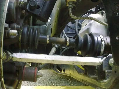
It might help to visualize the outer link attachment point in this pic to be 1" lower. There is a nice open area on the upright to install this lower attachment (but you may need to run larger diameter wheels to clear the lowered position):
[This message has been edited by fieroguru (edited 11-17-2011).]
Thanks for contributing to this thread 2002z28ssconv. It sounds like you've put a fair bit of thought to your comments. (If it had been me though, I think I would've gone down to the hotel bar instead) You've already started thinking about how to modify the rear suspension geometry while I'm still stuck finishing up the front assembly drawings. To be frank, I haven't spent any time assessing modifications yet, but I'll see if I can provide some feedback on you're thoughts.
quote
Originally posted by 2002z28ssconv:
I'm not a suspension expert by any stretch of the imagination...
Excellent, you'll be right at home with the rest of us blind people trying to lead the other blind people!
quote
Originally posted by 2002z28ssconv:
I don't have any of your fancy simulation software so all I can do is imagine the parts in my head.
Join the club... these drawings are done the unsophisticated way... basically an electronic etch-a-sketch with the added feature of an erase button instead of having to shake the screen.
quote
Originally posted by 2002z28ssconv:
Wouldn't the shorter front link induce bumpsteer? My imagination says it would pull the front of the hub inward as it moved upward at a faster rate than the rear arm would. Is this small amount of bumpsteer actually desirable or not?
Your intuition is correct. The greater the compression of the rear suspension, the more the rear tires toe-in. Conversely at the front end, the placement of the outer tie rod end outboard of the plane described by the upper and lower ball joints should make the front wheels toe-out slightly under compression. I assume GM designed the suspension this way to induce understeer, being safer and more predictable for the average driver with a tail-heavy car.
If you want a more neutral steering car, you can either design the understeer out of it with new geometry like you propose, or play around with spring and/or swaybar rates to achieve either more or less body roll at either end to limit the amount the suspension compresses and therefore toes-in or out depending on which end of the car we're talking about. How much the rates should change is beyond the level of understanding that I'm at currently. I suspect most people just experiment on a trial and error basis using adjustable swaybars and/or swap springs until they're happy.
quote
Originally posted by 2002z28ssconv:
If the two lateral links were to be moved up 3 cm (just over an inch) the maximum camber gained before the strut>knuckle>cradle angle exceeds 90 degrees is approximately 2.2 degrees over the stock mounting locations.
I didn't check the math, but keep in mind that changing the angle between the strut and the lower control arms can be accomplished several ways. Raising the inboard link mounts seems feasible since there are some who have already done this without any interference from the transmission, so certainly that's a viable way. Another way is to move the top of the strut inboard. Finally if you're planning a widebody, you can use longer control arms to move the knuckle outboard, yet keep the strut top mount in the OEM location effectively making the angle between the links and the strut more acute.
quote
Originally posted by 2002z28ssconv: The camber increase using stock mounting was 2.047. But at this point a stock car probably has more body roll than 2 degrees, so the end result would be positive camber in relation to the pavement.
According to Road & Track (Sept '83), the '84 four cylinder car reported roll angle (which was probably more heavily sprung than the '88 GT's, and a lighter car too) was 3.5 degrees per g. If I understand this correctly, given the max lateral acceleration of the '88 stock car with stock tires being about 0.83g (R&T Oct '87), then the max roll angle would be (0.83 g X 3.5 deg/g) = 2.9 degrees. Bearing in mind further research would have to be done to get a better roll angle rate for the '88, it's a start.
As for the effect of raising the mounting point of the forward inboard lateral link, and moving it forward and inboard, it's too much for my tired brain right now. Certainly something to look further into though. Maybe others can comment on this with their thoughts.
Your on the right track. To achieve my results I have lowered the knuckle mounting point about an inch, deleted the trailing link, and mounted the front link (now lower control arm) in about the same location as the trailing link was on the front of the cradle. I have moved the cradle mounting point up and outward (up over 3” in some simulations). Moving the front control arm forward has added stiffness and eliminated interference with the transmission.
To achieve my results I have lowered the knuckle mounting point about an inch, deleted the trailing link, and mounted the front link (now lower control arm) in about the same location as the trailing link was on the front of the cradle.
So you've gone from a three link design to a single LCA like the '84-'87's? Time for some pictures or drawings of this.
[This message has been edited by Bloozberry (edited 11-18-2011).]
Originally posted by aaron88: Also I have been assuming that I wanted about 3” of suspension travel with about 2 degrees of body roll (gives me about 1" vertical tire travel at max lateral G with about 2 degrees body roll. ie 325 lb/in rear spring). .
In my opinion, that's pretty slim. I think Fieros stock had 4"ish of jounce travel... might want to allow for 5 degrees of body roll also. Transient roll during rapid transition maneuvers is going to be greater than the steady-state roll for which you're designing.
[This message has been edited by Will (edited 11-18-2011).]
Actually that's kinda what I had in mind too. After Blooz mentioned the loss of lateral strength if the front link was at an angle, I had a vision of connecting the front link to the rear link which would create more a control arm.
I'll make a sketch tonight so you can see what I'm thinking about.
The suspension is capable of more travel, the 1” jounce at 2 degrees is just what I calculated to obtain my desired spring rate. I’ve included for the majority of variables so the variance should be only moderate once I hit real world. I’ll record the actual figures and make adjustments to the design. Then repeat as required.
I don’t have 3D CAD yet but I’ll clean up a vector sketch so you can see the top view of the lower control arm. At present I’m planning to use three ball joints and one polly or rubber mount.
.
[This message has been edited by aaron88 (edited 11-18-2011).]
While drawing these I noticed that the axis running through the inside joints of the lateral links is almost perfectly in line with the front pivot of the trailing arm. But the trailing arms pivot is higher than the lateral links' axis. So they don't intersect. But right now the three pivot points almost share a common axis.
Moving the front lateral link's pivot inward will move the axis away from the trailing arm. I think this is going to cause binding and stress on the links and mounting points if we lock the two lateral links together. They'd be fighting against the path that the trailing arm wants to take. Yes we could remove the trailing arm all together. But I'd rather keep the trailing arm for now. I expect to be putting a huge amount of power into this car and don't think that removing that bar would be a good idea. At least not for me. Plus from what I was reading on the other "build thread" removing the trailing arm would affect the anti squat calculations. I haven't quite got my head wrapped around that formula yet.
So I left the axis and trailing arm as they were, just moving the front link forward. This will reduce stress and still allow the lateral links to move upward for additional camber.
I really don't know how much deflection would occur under heavy side load. But just in case, a simple solution would be to either weld a bar between the two lateral links to triangulate the angles, or my preference, welding an attachment point onto each link so that another adjustable bar with rod ends could be attached. They would still be triangulated but you could tweak the length of that third arm when the length of the other two are adjusted for the allignment.
I haven't forgotten about moving the outer pivoy points downward. I just don't have a good solution for how to do that yet.
[This message has been edited by 2002z28ssconv (edited 11-20-2011).]
The suspension is capable of more travel, the 1” jounce at 2 degrees is just what I calculated to obtain my desired spring rate. I’ve included for the majority of variables so the variance should be only moderate once I hit real world. I’ll record the actual figures and make adjustments to the design. Then repeat as required.
I don’t have 3D CAD yet but I’ll clean up a vector sketch so you can see the top view of the lower control arm. At present I’m planning to use three ball joints and one polly or rubber mount.
.
This is the same as my third picture but with the front lateral link removed, right?
While drawing these I noticed that the axis running through the inside joints of the lateral links is almost perfectly in line with the front pivot of the trailing arm. But right now the three pivot points almost share a common axis.
Coincidence. Not relevant to the design at all.
quote
Originally posted by 2002z28ssconv: Moving the front lateral link's pivot inward will move the axis away from the trailing arm. I think this is going to cause binding and stress on the links and mounting points if we lock the two lateral links together. They'd be fighting against the path that the trailing arm wants to take.
Not the case at all for either rubber bushings or spherical bearings.
This would only be a problem if you used single axis hard bushings or bearings in the lateral links.
This would not work. The forward control arm would not function with this configuration. The pivot axis at both ends of the control arm must be parallel to each other. What you show in that picture would cause the knuckle end of the link to rotate - the pivot axis would not hold it's horizontal position.
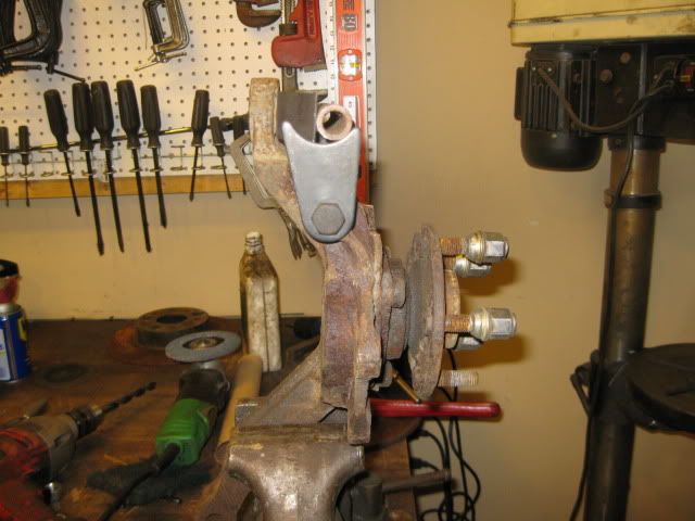
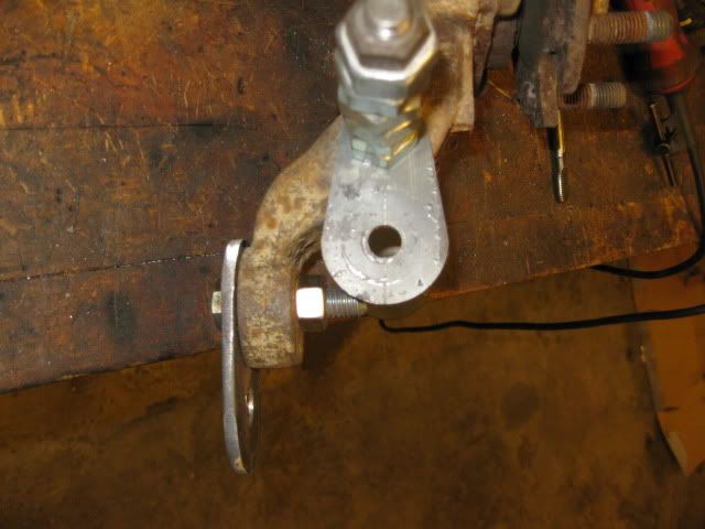
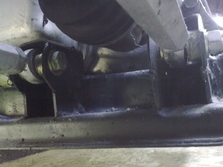
Here is a very quick/rough mockup of how it would be rather simple to lower the outer links on the 88. In this mockup they are lowered 2 1/8" for reference purposes. If you used stock bushings, you would want to mill the upright for the thickness of the brackets, but if you are using rod ends, then you could shorten the spacers.
The unknown is how much lower you could go w/o having wheel interference issues, the the larger diameter, the more room you would have.
Hmmm. That would be a lot easier than raising the inner mounts.
I agree. I also took a look at a spare set of rear knuckles today. Guru is right on with his mock up. You really wouldn't even have to do any cutting or welding to the knuckle or cradle, just bolt these on.
This would not work. The forward control arm would not function with this configuration. The pivot axis at both ends of the control arm must be parallel to each other. What you show in that picture would cause the knuckle end of the link to rotate - the pivot axis would not hold it's horizontal position.
For those interested, I posted the final top view drawing of the front suspension in my build thread, plus two tables of X-Y-Z coordinates which locate all of the front and rear suspension components in space. Zac88GT has already taken the coordinates of for the front suspension and produced graphs for the following:
Caster vs Bump Camber vs Bump Toe vs Bump Front Swing Arm Length vs Bump Side Swing Arm vs Bump Anti-Dive vs Bump Camber vs Roll Roll Center Position vs Roll
These graphs enable the comparison of the performance of future modifications to the stock front suspension. I'm waiting to see if he can model the rear suspension in the same way.
Here is a very quick/rough mockup of how it would be rather simple to lower the outer links on the 88. In this mockup they are lowered 2 1/8" for reference purposes. If you used stock bushings, you would want to mill the upright for the thickness of the brackets, but if you are using rod ends, then you could shorten the spacers.
ok, i will bite. i think this is genius! i keep staring at these photos, thinking it cant work. but i like it. is the ear strong enough to take the side loads that would get moved down to it? how far can the tube get moved toward the wheel to correct the scrub radius before things hit the rotor? by fixing the scrub radius could you eliminate the twisting the knuckle gets under acceleration? you would have to move the tube out some, as it drops to avoid making the scrub radius worse. could you change to a triangulated lower control arm to eliminate the trailing link (and its interference) would we be better off keeping the trailing link for the lifting properties it gives? how soon will someone do a graph to show the amount of improvement in camber gain? how soon will it be before you make a set?
ok, i will bite. i think this is genius! i keep staring at these photos, thinking it cant work. but i like it. is the ear strong enough to take the side loads that would get moved down to it? how far can the tube get moved toward the wheel to correct the scrub radius before things hit the rotor? by fixing the scrub radius could you eliminate the twisting the knuckle gets under acceleration? you would have to move the tube out some, as it drops to avoid making the scrub radius worse. could you change to a triangulated lower control arm to eliminate the trailing link (and its interference) would we be better off keeping the trailing link for the lifting properties it gives? how soon will someone do a graph to show the amount of improvement in camber gain? how soon will it be before you make a set?
I wouldn't call it genius, just a degree of insanity. I am sure the lateral link location at the wheel could be dropped 1" and moved further outboard by 1" w/o issue (but probably not on a 15" wheel), but haven't any idea how much it would improve the camber curve and if it would be at the expense of another suspension characteristic.
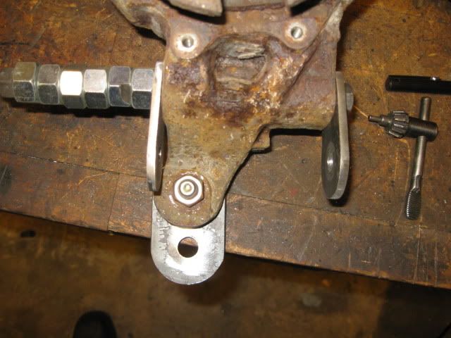
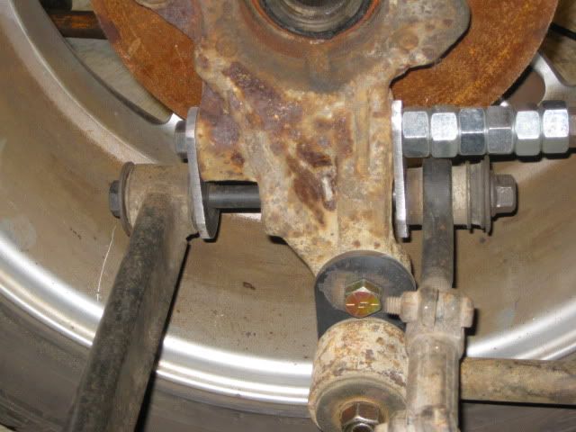
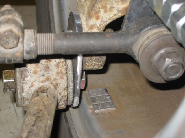
After thanksgiving I will be pulling an 88 into the garage to document my 13" brake upgrade, and at the same time I will probably go ahead and make one of these relocation brackets to test fit and run it through full compression and full extension to prove that everything clears and find the limit at which the trailing link must be modified (offset the tube to the bottom side of the bushing to allow more clearance for the lateral/toe link). The tabs on the end are 3/16" steel and they will be drilled for the long bolt sleeve to pass through them and be welded solid from the back side. That in addition to the support that can tie back to the trailing link ear should be stout enough to work w/o deflection issues.
I am not a big fan of eliminating the trailing link on a stock cradle for 2 main reasons. Doing so would require relocating one of the inboard links, then triangulate the setup, then hope the inboard mounts hold at the cradle as they were never designed to support the braking/acceleration and road bump forces. It would also kill one of the best features of the 88's... separation of the lateral and fore/aft forces. Since they are separate, you can run rod ends for lateral control/precision and rubber bushings in the trailing link to minimize road/bump harshness. Once you make the lateral links pull double duty, lateral control via stiffer bushings/rod ends will come with an increase in ride harshness.
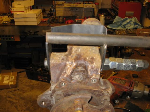
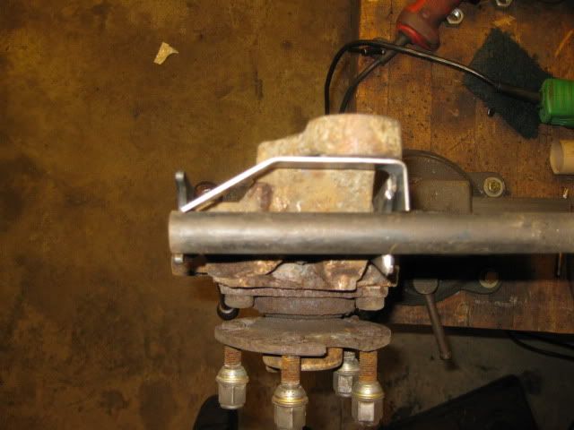
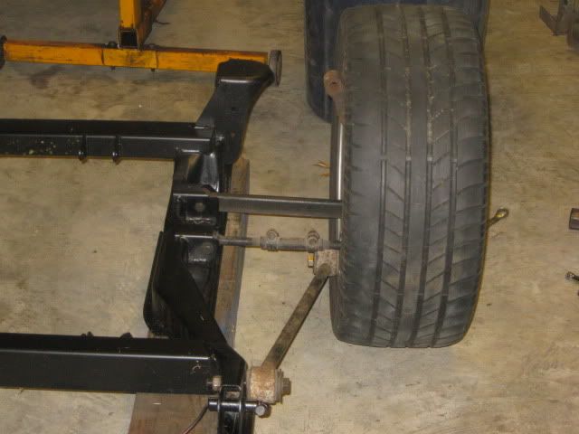
Here is a little proof of concept mockup. I fabbed up some better brackets to lower the lateral link and trailing link locations at the upright 1 1/2" just to see where things ended up. This modification would restore the suspension geometry back to stock for a fiero that is lowered 1 1/2".
The trailing link gets pretty close to the 16" wheel
There is still quite a bit of work to still be done from a reinforcing/gusseting standpoint, but it seems like a workable solution.
I'm a little suspicious about the anti-squat curve. It looks more to me like the program used the formula for a solid axle rather than an independent rear end. I've already shown in a previous drawing that the anti-squat for a stock '88 Fiero is about 28.4% which is the practical limit for an IRS, while your graph shows 75% at ride height for Fieroguru's modified lower links, and 58% for the stock config.
(Edited for more info)
[This message has been edited by Bloozberry (edited 11-23-2011).]


 You've already started thinking about how to modify the rear suspension geometry while I'm still stuck finishing up the front assembly drawings. To be frank, I haven't spent any time assessing modifications yet, but I'll see if I can provide some feedback on you're thoughts.