Originally posted by josef644: I would think the FP access hole has to be the same.
The fuel pump itself is bolted to the sender. So the physical size of the fuel pump is nearly irrelevant.
Everything else being equal I would suggest the more powerful pump. With a fuel injected engine it's relatively harmless to have too much flow, but not enough can make your engine run dangerously lean.
I went to RockAuto and looked up the fuel pump for a 1993 Deville, and a 1988 Fiero GT. Both used the AC Delco EP378 fuel pump, $78.79. 1987 Fiero Gt used a different one, EP240,$80.79. Two bucks difference. I was thinking that the 87 and 88 Fiero' both had the same enlarged just a bit fuel tank. I would think the FP access hole has to be the same.
The Caddy pump I is used from a '92 Deville and the motor is about twice the diameter of an '88 Fiero V-6 fuel pump ( and I personally think size matters on electric motors). I had to grind on the fuel sending unit and enlarge the hole in the tank by about 1/16" on 1/2" of the circumference to get it in the tank. This project also entailed modfications to the fuel sending unit to mount the pump but I don't remember exactly what they were. It's a tight fit but it can be down.
In your case I'd just pull the pump from the '93 Deville (whatever it is) and use it. If it's the same as a Fiero pump it's a piece of cake and you save $80. As I remember removing the gas tank on the Caddy was no big deal.
The Caddy pump I is used from a '92 Deville and the motor is about twice the diameter of an '88 Fiero V-6 fuel pump ( and I personally think size matters on electric motors). I had to grind on the fuel sending unit and enlarge the hole in the tank by about 1/16" on 1/2" of the circumference to get it in the tank. This project also entailed modfications to the fuel sending unit to mount the pump but I don't remember exactly what they were. It's a tight fit but it can be down.
Ohh I can't think of a reason that I would want to cut a larger hole in a gas tank. There are plenty of pumps that are only minimally larger, I would have gone with the Corvette or the Walbro before I started grinding on a gas tank.
Ohh I can't think of a reason that I would want to cut a larger hole in a gas tank. There are plenty of pumps that are only minimally larger, I would have gone with the Corvette or the Walbro before I started grinding on a gas tank.
I had about 80 reasons to use the Caddy pump. The tank had been thoroughly cleaned with lacquer thinner and then hot water and TSP. There was no explosion risk.
M Moose, Fieroseverywhere, I am starting to work on my harness for my 4.9 swap. I will be going to go get my 87 Coupe to put this in the next 8-9 days. I removed the body connector (two 7MM screws) from the wiring today, and started removing the black plastic harness protector stuff.
I was looking at another guys thread requesting help about Pin 'C' on the round transmission plug. He was removing the two part rectangular connector with one small bolt in the center, and joining the ends back together. Are all you guys removing this?
Is there room in the ECM area for this,or have you guys been mounting it in the engine compartment? If it needs to go, I am gonna start in on this and have it done when my care gets here. Thanks Joe Crawford
[This message has been edited by josef644 (edited 04-26-2009).]
M Moose, Fieroseverywhere, I am starting to work on my harness for my 4.9 swap. I will be going to go get my 87 Coupe to put this in the next 8-9 days. I removed the body connector (two 7MM screws) from the wiring today, and started removing the black plastic harness protector stuff.
I was looking at another guys thread requesting help about Pin 'C' on the round transmission plug. He was removing the two part rectangular connector with one small bolt in the center, and joining the ends back togeather. Are all you guys removing this?
Is there room in the ECM area for this,or have you guys been mounting it in the engine compartment? If it need to go, I am gonna start in on this and have it done when my care gets here. Thanks Joe Crawford
Just remember to take your time - if you rush, you may make a mistake (and those can be tough to find later).
Transmission plug - I have only done manual cars, so I can not comment on transmission plugs - maybe point me to the thread and I can have a look. The only 2 part connector I an aware of right now is the C500 - is that what you are refering to?
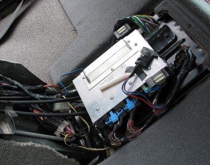
My ECM is mounted in the stock location, you have to modify the plastic bracket a bit for it to fit (make a notch in the side for the top most plug) - I will see if I have a picture of mine I can post.
Here is a picture of it, I didn't know the number of it,or on any of my two printouts from Fiero Addiction, or this thread. They call it "Engine to Dash Connector Mating Side".
Here is a picture of it, I didn't know the number of it,or on any of my two printouts from Fiero Addiction, or this thread. They call it "Engine to Dash Connector Mating Side".
That is the caddy C225 connector. I used it as a quick connect for the engine harness. I still used the fiero passthrough for the firewall. When pulling my engine out I just disconnect the C225 and don't have to touch anything in the interior. I have a pinout for it though I believe there is also one on the fieroaddiction site. The pinout will only help so much if you decide to use it. You will still have to connect some wires where there are empty spaces (use the pins from the unused wires). It was more work during the install but should save time during maintence and repair. You can also use this instead of the fiero passthrough if you are willing to trim the firewall for clearance.
Option 2: Cut the wires on the engine side of this connector, feed them through the firewall, connect to PCM connectors and C203. Cleaner looking install if that is what you are going for.
[This message has been edited by Fieroseverywhere (edited 04-26-2009).]
My ECM is mounted in the stock location, you have to modify the plastic bracket a bit for it to fit (make a notch in the side for the top most plug) - I will see if I have a picture of mine I can post.
Cheers,
Option 2 : Use the ECM mount bracket from an 87-88 Duke. Will fit with no modifications except for screw holes to mount it.
Fieroseverywhere you have this C225 in the engine bay? I have purchased a 1987 Coupe for my 4.9 swap. I had already purchased me an 87-88 ECM tray. I have all the wiring diagrams. Joe
[This message has been edited by josef644 (edited 04-27-2009).]
Here is a picture of it, I didn't know the number of it,or on any of my two printouts from Fiero Addiction, or this thread. They call it "Engine to Dash Connector Mating Side".
I usually cut that out. If you cut the wires right at that block, most of the wires will be long enough to reach the ECM in the stock location (provided you remove all the tape and reorganize them, there are only a couple of wires that need to be lengthened) - I wire the car in such a way I can remove the engine harness the same way as the stock Fiero one (unplug the ECM, C203 and disconnect the grounds and pull though the bulkhead).
BTW - here is the picture of my ECM (the thing taped to the front is my passkey bypass) - also the white plug near the C203 is for my cruise control (4.9 controlled):
[This message has been edited by Mickey_Moose (edited 04-27-2009).]
Fieroseverywhere you have this C225 in the engine bay? I have purchased a 1987 Coupe for my 4.9 swap. I had already purchased me an 87-88 ECM tray. I have all the wiring diagrams. Joe
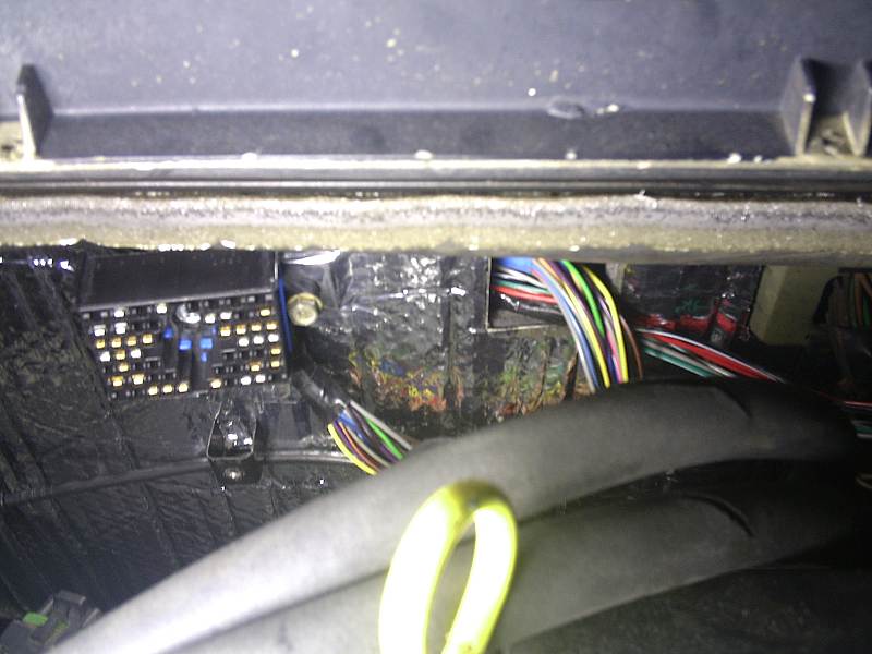
Yes. I used the fiero passthrough for the firewall. The C225 is bolted to the firewall on one of those tabs I no longer needed. Here is a pic before loom and such..
I just unbolt that connector to remove the engine. My engine harness is actually 2 pieces just like the original caddy one.
[This message has been edited by Fieroseverywhere (edited 04-28-2009).]
Originally posted by Frizlefrak: OK guys....on this axle thing...Here's what I used. It's 3 years and 4000 miles later on the swap, and all is well. Anyone is welcome to come and drive it if they like...
Change the OUTER ends for those from stock Fiero axle ends from a MANUAL transmission car. Simple to do, takes 5 minutes per axle. Your new axles will bolt right up just like they were made for the car.
I don't know what else will work....but I do know that this combo WILL work.
OR...
quote
Originally posted by sanderson: Left side needs a 1989 Pontiac 6000 with light duty brakes Right side is an early 90's minivan (like a Silouette) with 3800 with Fiero manual CV joint swapped on to the outer end
It's pretty obvious that a drop-in Pontiac 6000 axle for the left side is easier and cheaper than swapping a Fiero CV joint onto a minivan axle. Rockcrawl recommends the Pontiac 6000 axle for the left side. Nobody on PFF has reported a problem with the Pontiac 6000 axle.
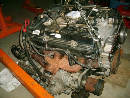
1. In this picture there is a green connector,to the left side of the alternator. The wire goes in, then out of the green part. Then ends up plugged into the alternator in a black plastic plug. Whats the green connector for? Where does it connect to? I cant find reference to it in my wiring diagrams. I borrowed Mickey Moose's picture:
2. All of these "Cruise Control" wires and connectors, can I just clip them out of the harness as I am not going to use these. Joe
[This message has been edited by josef644 (edited 06-21-2009).]
1. In this picture there is a green connector,to the left side of the alternator. The wire goes in, then out of the green part. Then ends up plugged into the alternator in a black plastic plug. Whats the green connector for? Where does it connect to? I cant find reference to it in my wiring diagrams. I borrowed Mickey Moose's picture:
2. All of these "Cruise Control" wires and connectors, can I just clip them out of the harness as I am not going to use these. Joe
IIRC the green plug only has the on wire in it on the one side - this is used for grounding out the alternator to disable it during the proceedure to set the timing.
If you are NOT using cruise, you can remove them from the harness - for unused wires on the ECM plugs I just grab them and yank the pin out of the plastic connector. ONLY DO THIS after you have started the motor and it is running, the pins are damaged when you do this and can not be put back in. But feel free to yank the cruise wires, just double check before you remove them.
Great information. I had run into a little snag on my harness yesterday. My 93 engine still had its injector wiring part of the harness on the injectors. My 91 harness uses two connectors, one for the even bank, and one for the odd bank. The 93 only has one connector on the injector group harness for all 10 wires. I still had 90% of the 93's harness in the garage, and I think I can splice in the 93 injector connector part into the 91's engine group wiring harness. There was only one difference in the color of the wiring to deal with. I had access to the 92-93 wiring off of your thread from FieroAddiction, and Alldata.com, as well as the available 91's harness diagrams. I am gonna lay all of this out on my 4.9 Wednesday morning, and get this all sorted out in a neat and orderly fashion.
[This message has been edited by josef644 (edited 06-22-2009).]
Great information. I had run into a little snag on my harness yesterday. My 93 engine still had its injector wiring part of the harness on the injectors. My 91 harness uses two connectors, one for the even bank, and one for the odd bank. The 93 only has one connector on the injector group harness for all 10 wires. I still had 90% of the 93's harness in the garage, and I think I can splice in the 93 injector connector part into the 91's engine group wiring harness. There was only one difference in the color of the wiring to deal with. I had access to the 92-93 wiring off of your thread from FieroAddiction, and Alldata.com, as well as the available 91's harness diagrams. I am gonna lay all of this out on my 4.9 Wednesday morning, and get this all sorted out in a neat and orderly fashion.
Wouldn't it just be easier to use the other injector wiring harness? The less splicing the better (less chance of a screw up, less chance of there being a problem in the furture, etc). but that is just me.
Originally posted by Mickey_Moose: Wouldn't it just be easier to use the other injector wiring harness? The less splicing the better (less chance of a screw up, less chance of there being a problem in the furture, etc). but that is just me.
I don't have access to the other harness on the old 91 Deville engine. How do I remove the injector harness from the injectors? I havent found that in the books, or on AllData.com.
Originally posted by josef644: I don't have access to the other harness on the old 91 Deville engine. How do I remove the injector harness from the injectors? I havent found that in the books, or on AllData.com.
Congrats Josef on getting this far. I have been having problems with my computer deleting all my cookies so I'm not sure which threads have been updated and which have not.
I'm not sure if you saw this yet or not but when doing the wiring for the injectors be sure to use the 92-93 diagrams Mickey posted here in this thread. You will immediately notice a difference between those and the 91 diagrams listed on fieroaddiction.com. The 92-93 diagram actually have everything as it should be. Be careful of one thing though. There are two wires that are the same on the harness (same color). Make sure you put them in the correct spot and check them with a multimeter to be sure. I don't recall exactly but I remember having a problem with that.
If you don't find those diagrams here I can e-mail you a copy also... if I haven't already.
There are many of the same colored wires in the 91 harness. Lots of green and green w/wt stripe. I have been checking them one at a time with the meter. I also set up a battery charger and used a test light to find the correct holes in the ECM plugs faster. If the light is on I had the correct hole. As I removed the caddie C225 connector I soldered the wires back togeather an put heat shrink on them. Every wire was done one at a time, and ohmed out after the soldering. Took a while, but I dont want any errors or crossed wires to figure out later.
This has really not been real bad so far. I now know each wire , and have marked all of the loose ends with tape as to where they should be connected once merged with the C203- C500 harness. I have one connector I don't know where it goes yet, but I am sure once I set this on the engine and start laying it al out I will find the empty sensor or what ever. It was in the engine harness, but was not a part of the ECM plugs wires.
And yes there was two wires different than what was in the 91 diagrams, the # 3, and # 4 in the diagrams were different. I used the correct ECM connector socket to establish the correct injector wire, not the wire color.
Joe
[This message has been edited by josef644 (edited 06-24-2009).]
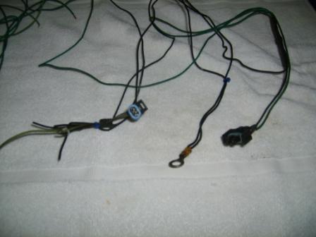
The wire colors are Lt Green, Dk Green, and the black wires come to a common grounding eye. Both had the insulation toasted right at the connectors. Both have a light blue " gruved rubber band seal". If you want an un compressed photo PM me your home e-address and I'll get it on the way. I have to compress all pictures before posting here on PFF
Yea send me the full size pic. Can't quite tell what it is. The email tab right here...........^^^^ has the right address.
Is that a part of the caddy harness or fiero? Oh wait, blue rubber seal. I was looking at the other plug..... checking...
OK. I just confirmed. I'm not entirely sure which connector that is. I did not use it on my harness. This leaves a few options though...
AC Cruise Auto trans Possibly the stock caddy CTS connector. (this needs to be switched for a 3 wire connector anyways)
If its part of the fiero harness then it could also be other options. I started with an 85GT with no AC, cruise, and had a V6 so it could be something to do with that. I'll keep checking and see what I can come up with. Hopefully someone else will be able to chime in also.
[This message has been edited by Fieroseverywhere (edited 06-25-2009).]
It was part of the Caddie harness but was not connected to the ECM plugs or was not connected to (spliced to) a sensor that was. There were two grounding eyes in the Caddie harness, this was one of the two. I'll send you a picture later today.
I have some chores do attend to before it gets 103* again. Heat index was 108 here yesterday.
Joe
[This message has been edited by josef644 (edited 06-25-2009).]
As asked - which harness?? If all your sensors on the 4.9 are plugged in, don't worry about these (don't forget about the plugs on the transaxle).
BTW - the ECM plugs are marked which pin is which (look close and you will see the pin numbers stamped) - your method is a good ideal, but I am too lazy to keep getting up and down to go to the engine bay to move the battery (plus I am getting too old for that).
Sorry , I should have said that it was part of the 91 Deville harness, the one I am using for my swap. I do have 90% of the 93 Deville's harness. They cut it all off at the firewall. 107* outside right now.
Fieroseverywhere I just sent the unresized photos.
Joe
[This message has been edited by josef644 (edited 06-25-2009).]
I just finally got my speedo to work. Thought I'd toss the info out here for those that have problems like I did.
Basically I bought the signal clamp circuit from fieroaddiction, wired it in and... nothing. Speedo would zero out but never moved. SO I decided to make my own circuit. Then I checked the wiring a dozen or so times. Still nothing. Long story short the problem ended up being a bad output on the PCM. Good thing for us there are 2 on the caddy PCM.
So if your speedo doesn't work when you use output B11... switch to B12. Honestly, I'm just glad to know how fast I'm going.
Hey Mickey, Want to add this to the first post with the other speedo info? Could come in handy to some later.
[This message has been edited by Fieroseverywhere (edited 07-02-2009).]
Temp sender (also see NOTE): Located in the thermostat housing (from a 2 wire unit to a 3 wire): use these parts numbers for the correct sender: GM 10096181 AC-Delco 213-815 Borg Warner WT3024 CarQuest TX66 Filko CS-43 GP Sorensen 38-5124 Niehoff DR134TA Napa/Echlin ECHTS4020
Connector comes off a 92 Cavalier or the 3800SC - but most 80-90's GM tps sensor plug will work.
pin "A" BLK wire on the switch goes to ecm "E11" pin "B" YEL wire on the switch goes to ecm "E16" pin "C" GRN wire on the switch goes to C500 gage connection
NOTE: Some 4.9's have a temp switch in the side of the head: 1) if you car does NOT have a temp gage and just an idiot light you can leave the stock 4.9 sensor in the thermostat housing - wire this to the ECM, the one in the head gets wired to the idiot temp light on the dash. 2) if you have a temp gage in your car you change out the sensor to the above info and wire, the head temp switch can be thrown out (or used for an additional light that you have added to the dash).
Just wanted to toss something out there on this...
For most fieros this is the correct way to wire this in. The only problem I found comes for those who have fixed their pegging temp gauge. Here is a link on how to do the fix... http://www.fierosails.com/tempgage.html
You have to switch the 2 pairs of wires to correct this mis-wiring from the factory. Problem is for us 4.9 guys we have switched out our CTS's for a 3 wire unit. This makes it a little harder to determine which wires to switch. To make matters worse the 3 wire unit does not run a temp light so technically there is one wire missing from the equation.
The two wires that need to be switched in the gauge cluster do not change. While facing you gauges, the left connector on the back pin 11 needs to be switched with the right connector pin 13. This is the same for all fieros that have this problem.
The two wires in the engine bay that need to be switched are located at the C500. C2 (dk grn/wht wire V6, tan wire L4) and D3 (dk grn wire) are the ones in question. In a fiero with a stock CTS you simply switch these wires at the connector.
Option 1: In a 4.9 fiero you probably won't even have the wire in D3 hooked to anything... unless you are lucky enough to have the caddy head temp sensor on your engine and decided to use it. You probably hooked the CTS wire to C2 to run the gauge. If you, instead, connect pin "C" of your CTS to D3 of the C500 instead and switch the 2 wires at the dash connectors your temp gauge will not peg on startup anymore.
Option 2: An even easier way to take care of this is to remove and tape up the Dk grn/yellow wire from G1 or G2 (varies based on year) from the ignition switch connector. This will eliminate the bulb test feature. Since most of us are not using a temp light anyway it won't make a difference if we take care of it this way. If you are running the caddy head temp sensor use option 1.
Most of my fieros I don't even bother with this fix. The temp gauge in my 4.9 though, sticks when it pegs and drives me crazy. I just had to fix it. Anyways, thought I'd share.
[This message has been edited by Fieroseverywhere (edited 07-02-2009).]
Does the distributor 12v supply need to be switched or can I hook it to the battery distribution terminal under the c500? Also how has everyone connected the tach lead? What source did you use for the connector?
Does the distributor 12v supply need to be switched or can I hook it to the battery distribution terminal under the c500? Also how has everyone connected the tach lead? What source did you use for the connector?
For dist power I used the pink wire from the C500 (pin E3).
For tach the white wire from C500 (pin C3). For the tach connector @ the coil I used a second dist power connector and shaved off the tab that keeps it from being used on the tach side. You can also find any GM vehicle with HEI ignition and a Tach and swipe a connector from there.
Does the distributor 12v supply need to be switched or can I hook it to the battery distribution terminal under the c500? Also how has everyone connected the tach lead? What source did you use for the connector?
tach lead = find an HEI distributor in the junk yard that has a tach lead on it and use that one - the BAT lead can be modified to work in the tach position (so I have heard).
[This message has been edited by Mickey_Moose (edited 08-24-2009).]
Originally posted by Mickey_Moose: tach lead = find an HEI distributor in the junk yard that has a tach lead on it and use that one - the BAT lead can be modified to work in the tach position (so I have heard).
Good info how about the 12 volt lead should that go straight to the battery or should it be switched? The FSM really does elude to either. I actually found a website that has the tach connector and the 12v connectors and a bunch of other GM stuff. Here is the link. It's fairly inexpensive and less than it would cost me to drive and hunt for one. http://www.repairconnector....subcatid/0/id/293731
[This message has been edited by Carrluvr (edited 08-24-2009).]