Well, I do appreciate all the input. I'm ultimately going to have to decide, but I do want something that's going to give it a serious grin-factor. I'm not going to do all this work and expense to build a stroker and then wimp out on the cam, that just doesn't make sense to me. I submitted a request to Comp for some suggestions, although I suspect they'll come back with the same cams I've already considered, being the thumpr, the 282, and the 2480. Really, from what I've seen, a lot of opinions are the the 282 is popular with the 383 crowd, but some think it's pretty mild, and many recommend the 288. But running it through CamQuest (which has routinely given much higher numbers than DD) it shows a significant loss in power compared to the 282. I suspect the heads are the bottleneck there as a lot of 383 guys are running Darts or Eagles.
I guess shooting at a HP number that your tranny and final drive can handle, however you get there would be key?
I'm basically shooting for about 400hp, 450 or more ft/lbs.
Although, after reading the thread about that 3800 that's pushing over 800 I'm thinking I might as well put a Briggs and Stratton lawn motor engine back there.
I know what you're saying. And I also realize the trade-offs. It may not seem like it but this really isn't my first build. Although, it's probably the most *deliberate* build I've done in about 20 years.
Interestingly the guy at Comp suggested the 288 profile, which is slightly more radical than the others I was looking at. DD doesn't show it as producing any more power than some of the others. although the torque and HP curve are somewhat flatter.
So I got my heads back from the machine shop the other day. Yes, he's had them this long, but that's a different rant. The cam I'm going with is a Delta with a roughly .550 lift.
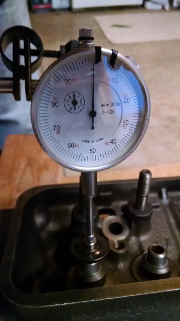
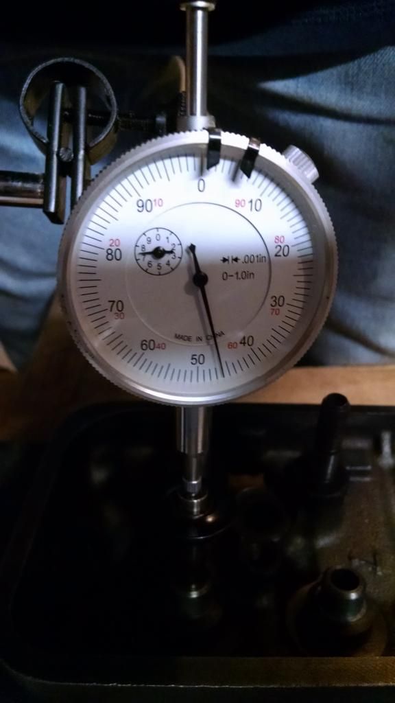
The Vortec heads supposedly allow only about .480 in stock form due to clearance issues between the valve retainer and the top of the valve guide, so I got the Comp valve guide cutter. I Started working on the heads, getting ready to cut the guides down. I popped a valve in and put on one of the new spring retainer assemblies- I'm using Comp LS1 beehives and new retainers and locks. But when I measure the clearance from the bottom of the retainer to the top of the guide it turned out that total travel is actually close to .750". Allowing for .100" that still leaves me .650" of valve clearance. I'm not sure if the new retainers are just shorter or what.
What the hell am I missing? Anything?
Retainer in contact with the top of the valve guide.
Originally posted by Taijiguy: What the hell am I missing? Anything?
Nothing, that is pretty much what I thought I had read. If you install a stock spring retainer, it probably protrudes much further down past the keepers and you will end up with something around the .480" range. The LS1 style retainers are higher and allow more lift with the same length valve stem.
Set two valves side by side with both style retainers to see the difference.
quote
Originally posted by fieroguru: I agree with Will, the only thing I would do is set them up to handle .550 lift - that used to require machining the valve guides, but now I think you can use the LS(x) retainers and behive springs and get there w/o machining.
I compared them side by side, virtually no difference in the depth of the spring retainer as it sits on the valve stem. Beats me why there's so much clearance. Unless it's actually spring bind that limits lift, but that's contradictory to everything I've read that indicates it's retainer to valve guide clearance that's the issue. Or more specifically, retainer to valve stem seal.
Since I was planning to cut them down I went with .530 seals, as that's what the Comp tool shaves the seal seat down to.
[This message has been edited by Taijiguy (edited 11-16-2014).]
No, but I allowed for the stem seal, it would be about .100", available lift (barring coil bind which shouldn't be an issue with the LS1 springs) will be about .650"
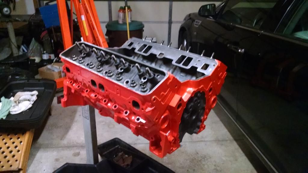
Got my block back from the machine shop, so have been working on that getting it ready to paint, which I should be able to do this weekend. I've also accumulated most of the parts with the exception of a few things I haven't quite decided on yet.
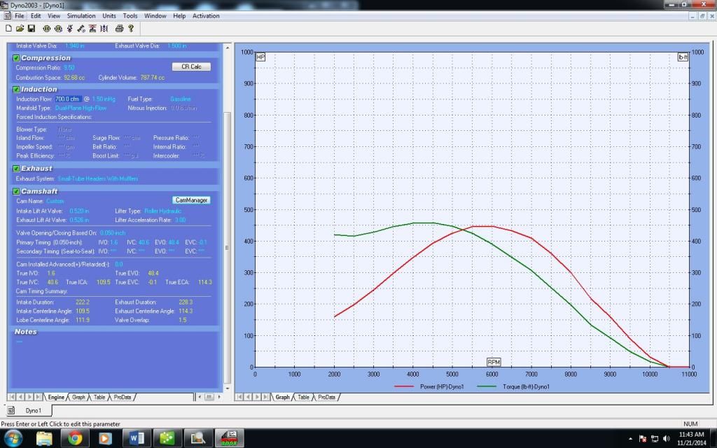
What really has me excited is that I got my cam figured out. I called Delta and talked to the guy there about what I wanted. I was a bit hesitant as the duration seemed pretty short at 222/228. But it compensates with a pretty decent amount of lift at 520/526. The guy at Delta was confident it would give me pretty decent torque / HP. When I got the cam the first thing I did was run the numbers through Desktop Dyno. I was hugely disappointed in the numbers (I don't recall what they were right now but they were bad) I was seriously considering calling them and telling them I wanted to return the cam.
Well today I decided that I wanted to be sure that I wasn't just careless and screwed something up when I entered the data so I ran it again and this time I added the actual flow data for the 906 heads. I'm not sure what I might have effed up the first time, but this time the numbers were very different. I think I'm gonna love this cam:
These numbers might be better than any cam I compared, and I compared a LOT of them using both DD and Cam Quest
Overlap is minimal so it won't be too lumpy and vacuum should be good. Should have decent manners. I had been vacillating on whether I wanted it to have a really aggressive sound at idle or not. I wouldn't mind it having a serious lump, but under the circumstances, I'm probably going to enjoy having it be something of a sleeper.
Edit- By the way, you just can't beat Delta's price- this is a roller cam which is much more expensive. From Comp or another manufacturer it would have been around 300 or more due to needing a small base diameter. This cam was 135 with the custom grind. If it performs as well as DD suggests it's more than worth it.
[This message has been edited by Taijiguy (edited 11-21-2014).]
DD isn't all that accurate, it can be ballpark if the settings are 100% right, but be careful with those estimations, don't hold them as law.
Yep, pretty much said that at the beginning of the post. It did give me a good comparison using all the same engine data and only changing cam profiles tho.
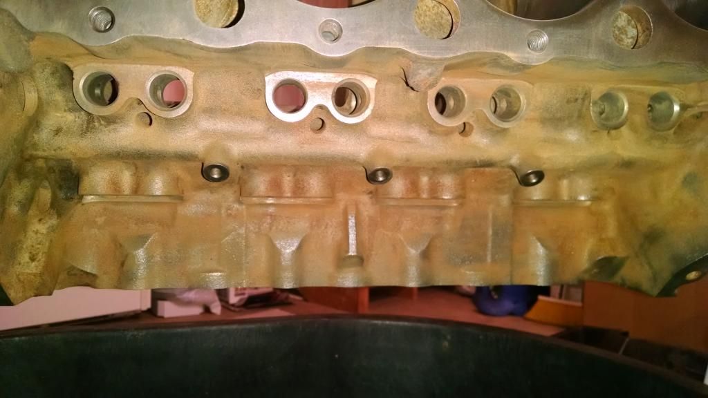
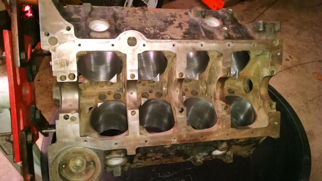
Been busy with the block. It had a lot of surface rust on it when I bought it. The guy at the machine shop complained that he couldn't get it rust free because of epa regualtions on the chemicals they use. I'm not sure I buy that, I'm starting to think he just may be a shi**y shop. Anyway, got the block back after having the cylinders honed, and supposedly cleaned. Lots of rust and paint still on the block, including the oil valley and the crankcase area. I've used a variety of ways to clean rust over the last 30 years, and without a doubt the method I'm going to describe is the absolute best method I've discovered.
I used a strong paint stripper to remove the paint, I went through a couple of times applying the stripper and scraping the old paint off. When I had most of the paint removed I used a heavy cup style wire wheel on an angle grinder to get the rest. I used picks and a Dremel to remove the rest. Once that was all done I washed the motor down with water, being as careful as I could to keep from getting water into the cylinders. You'll notice too that I did all this with the heads installed with 3 bolts snugged down. That helped minimize the amount of water entering the cylinders, which I did have coated with a nice heavy application of motor oil.
The trick to removing the rust was using a phosphoric acid solution. Home Depot sells it in gallon jugs for about 15 bucks. I applied the phosphoric acid with a cheap paint brush and kept it wet for about 15 minutes. Then I rinsed it off and dried the motor and shot WD-40 on it to keep it from flash rusting.
This is how the block looked when I got it back from the machine shop-
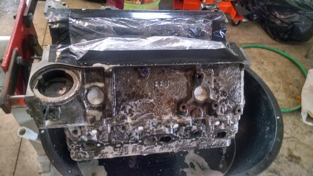
After stripping most of the paint I applied the phosphoric acid.
I used the POR-15 engine kit. I more or less liked the kit. It has 4 parts; a degreaser, a rust inhibitor solution, a primer, and the top coat.
I didn't get any pics after cleaning the block with the acid before painting, but I'll put up better pics later of the crank case and the oil valley, it's amazing how well that stuff worked, both areas look perfect.
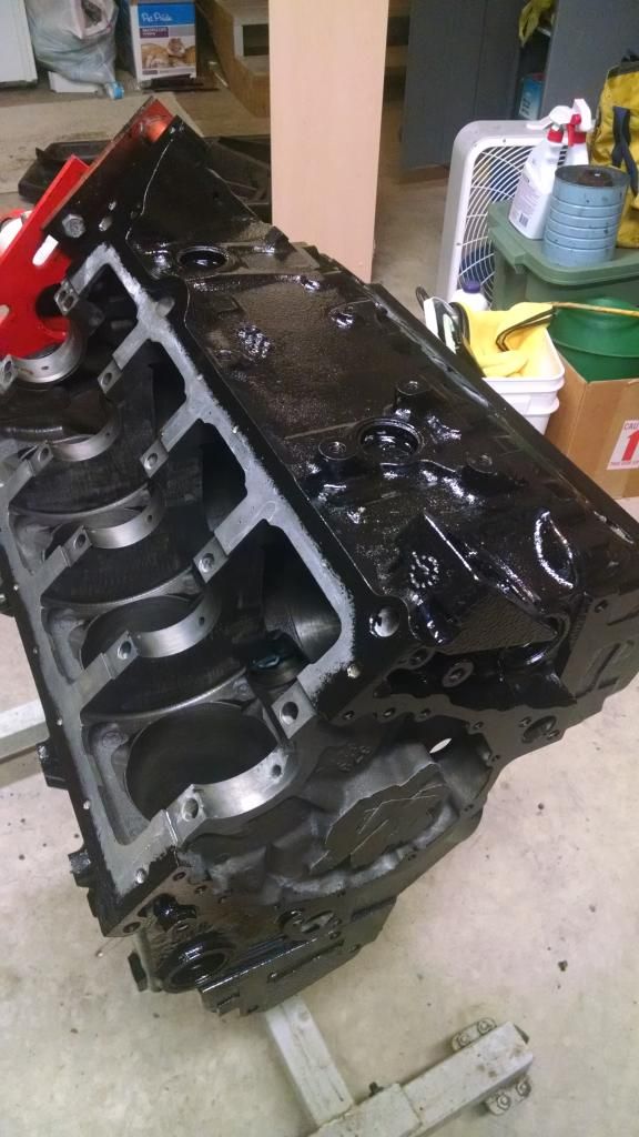
The primer applied really nicely to the preppped block. It flowed on beautifully and set up with a nice finish.
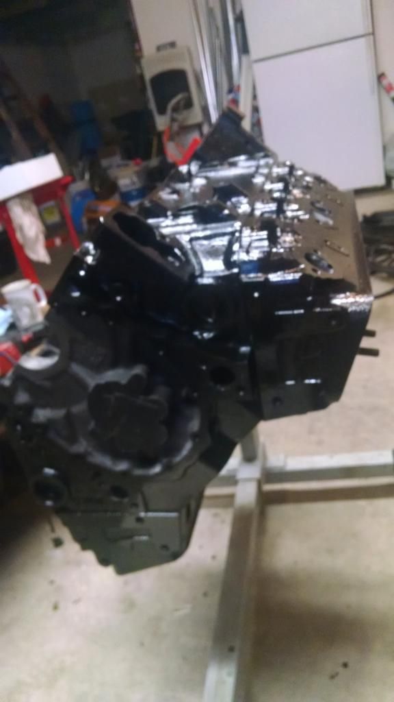
What I *didn't* like was that the top coat didn't apply nearly as well as the primer. They say to apply the top coat when there's just a little bit of drag when you try to wipe the primer coat. They say 2 to 6 hours. I figured as it was cold it might be on the longer side of that so I figured I had some time to kill. So I ran out to do some errands, came back after just a couple of hours, and it was almost beyond that stage. So I hurredly applied the top coat, but it went on terribly. It didn't stick well, and wouldn't go on heavy enough to cover without running. So I did the best I could with an initial coat and let it set up for the night. I was fortunate that the next day it was nice enough that I could spray the top coat. They supply a special thinner (toluol I believe) so I thinned it out a but and shot the motor with my spray gun. Even though the top coat gave me some aggravation, I have to say the end result is very, very nice, and I suspect it will hold up well.
I'm going to clean the oil journals myself, then I have to take it back to the machine shop to have the cam bearings installed. I'll assemble the heads this weekend, and with any luck, the shop will finish neutrally balancing the crank and have the rest of the assembly balanced so I can actually start to build. I really can't wait to hear this SOB run for the first time!
Got the block on the stand and set the upper main bearings. Set the crank in place and looked around.....no main caps.
Apparently the idiot at the machine shop lost them. Two weeks now and he hasn't found them yet.
I suspect I'll have to buy a set of replacements and take it some place to have it align bored, as I'm sure not taking it to him to be done. Then I'll have to sue him for the expense.
In the mean time I'll build my heads, but that'll only take a couple of evenings. Then I'll be dead in the water until that's resolved.
While you're at it, have the second shop QC the block... If the first guy was drunk enough to separate the man caps from the block there's no telling what goofy things he did with it.
This is an opportunity to get splayed 4 bolt caps, though
While you're at it, have the second shop QC the block... If the first guy was drunk enough to separate the man caps from the block there's no telling what goofy things he did with it.
This is an opportunity to get splayed 4 bolt caps, though
I thought about it. Overall, from what I can tell, his work really seems pretty good. But you're right about having the second shop check the work, I probably should. I also thought about the splayed caps, but that seems like kind of a waste for 450 horses and a cast crank. Would you go to the extra expense? I don't know that I could recover that cost if I end up having to sue the guy. Splayed caps are expensive as hell, and then the front and rears are all separate. BTW, I saw a listing for caps on Ebay that went from 88-97, I can't figure out what would be different after 97, my block is a 98, I'm trying to figure out why those caps wouldn't work. Any clue?
Just out of curiosity, if you had to buy new heads, crank, block, et cetera, any reason you didn't go straight to a 400? They respond well to vortec heads provided you have the matching steam holes drilled and everything else is basically the same as any other sbc except you get an extra 50 or so cubic inches. Safe to assume it was just easier for you to find a 350?
I swear, this motor build is like a Greek tragedy. I spent a good portion of the weekend putting the rotating assembly in. It took longer than it should largely thanks to a crappy ring compressor. I've had it for about 30 years and it's always served me well, but it may be time to upgrade. Many tries and one bent oil ring later I'm proudly admiring my handy work. After a bit of self congratulations I slip the cam in. Now, I almost didn't do this part, thinking there's no way there could be interference. After all, this is a small diameter cam..supposedly. But as I was putting it in I noticed that the lobes weren't any smaller than the journals. So I turn the crank to get a couple of the rods up to their highest point in travel. Very carefully turn the cam. It goes around smooth as snot, then....stops. Sure enuff, it's bumping into the tops of the studs.
Obviously, I can't repeat the expletives I uttered. But then really all I could do was laugh. So an hour later I was right back to where I started from yesterday morning.
So now, after spending I don't know how much denero having the pistons and rods assembled, and the rotating assembly balanced, I have to buy new rods clearanced for a stroker, which I can get a set of Scat with ARP bolts for about 300. Then I have to have the original assemblies pulled apart. (The good news is the Scat rods are floaters, and my pistons came with clips, so I can assemble the rods and pistons) but then I need to have everything re-balanced, including the crank.
I guess the good news is, I figured this out now instead of after I tried to crank it over the first time.....
I will say, that after all the drama of dealing with this machine shop..the time it took him to get my stuff done, and then the hoorah with the lost main caps, I have to give the guy credit. His work seems to be spot on. I checked everything as much as a guy with limited capabilities of measuring such things can. Even though I've read about inconsistencies with Plastigage, it's been used for a bunch of decades. And yet every single one of the rod journals came out to have .002" clearance, the mains were right at .003 for the centers and .005 on the ends. So I guess even though I'm really disappointed in his turnaround, I have to give the guy credit for being damn accurate in his work, which is more important to me than how fast he can get it done....
Before you tear it all down, throw the timing gear and chain on with the camshaft zero'd in to see if it hits with everything properly timed. If the rods hit the peaks of the lobes, they might be out of the way when properly timed (breaking a timing chain would still suck!!!)
I already tore it down. What you're suggesting occurred to me, but it seems extremely unlikely that it would be the case, since cam interference is a common issue with strokers. Small base circle cams and rods clearanced for use in strokers (to me) suggests that interference may be frequent and timing isn't a factor. Plus, I'll just say that when I looked through the cam opening I could clearly see the tops of the rods extending into the cam space by a pretty fair amount, much more than I would have expected....maybe as much as a 1/4". Given that the lobes are only maybe a few thousandths below the diameter of the cam journals it would seem the interference is substantial.
I'm really only posting this for posterity. I know these SBC builds are pretty mundane at this point, but it's good for me to have a chronicle of the events. I got the interference issue resolved, I had the shop take a little off the tops of the rods and then once it was timed it cleared just fine. I was disappointed that there was any interference at all as if there's ever an issue with the chain it'll wipe out the entire motor, but it is what it is, so I'm running with it. So the internals are all installed and the cam timed. I need to check valve to piston clearance but I seriously doubt that will be an issue.
I'll bring the cradle in this weekend and start cleaning and painting that and finish powder coating the various parts and bits that need it. The plan is to use the cradle like a test stand and fire up the motor outside of the car. With any luck, and if the universe cooperates I'll hopefully be doing that in the next month or so.
making slow but steady process on the build. There's a lot going on, as always, but I'm making it a priority to get this thing at least on the road hopefully this summer, or early fall. I'm taking advantage of the weather to get the cradle prepped as I want to put the motor in place before I go much further in the assembly.
The cradle that came with the drop out was in great shape, so I decided to use it. The only bad place I could find was where the original bracket for the front mount had been removed. The metal was thin when it had been ground, and actually went all the way through in a few places. So I laid some heavy beads in that area to beef it up since it sits right below where the angle iron bracket is welded to the cradle for the new solid front mount. I also beefed up the welds on that angle iron as well. I then cleaned it up and stripped it down to bare metal and gave it the POR 15 treatment.
With the ability of aftermarket blocks to go to 4.250 bore, I'm curious about a 4.250 x 3.000 engine with 6.385 conrods... although probably not curious enough to actually build one. To make it worth the money, it would definitely need SB2.2 cylinder heads, which I *THINK* were still on 4.400 bore centers and not the R07's 4.500.
Would still just essentially be an SBC build though. Once you got past the engine build it would be just like every other Fiero with an SBC. That was my point, I think people are kind of bored with them by now unless it's something pretty unique. I remember being here early on and the first SBC builds were the things dreams were made of. Nowadays I don't think people here give them much thought. Like I said, the only reason I'm still posting is mostly just for my own chronicle of the events so I'll have something to refer back to if I ever need it.
Been having a pretty good weekend working on the car. A few hiccups here and there, and runs to the hardware store to pick up fasteners of all things. I must have a dozen coffee cans full of bolts and nuts and screws and crap and somehow I still don't have what I want or need. Anyway, I manged to work it so I've had the entire three day weekend more or less to myself to work on the Fiero. Despite the glitches, I'm making some pretty good progress.
I had previously stripped the cradle and painted it, so it was all nice and pristine-
Before anything I else I wanted to get the brackets for the sway bar as well as the bar itself installed, as I figured it would be easier with the cradle upside down. So I got that done first-
One of the things that held me up was that the bushings I got for the bar were 1-1/8" and the bar is 1-1/4 ", so I had to take the bushings to the basement and open them up on the drill press. About a half hour wasted there.
Once I had the bar installed I flipped the cradle over and got it set on the dolly, and made ready to put the engine in place. I also spent a bunch of time getting the remote oil filter adapter set up. I want to run short straight lines. Trip one to the hardware store was for new AN fittings as the old ones don't fit the new remote filter mount I got. Once I had the block adapter all sorted I put the engine on the cradle.
One thing I'm doing is beefing up certain parts of the engine mounting. I went with larger bolts between the front engine mount and the angle iron welded to the cradle. I stepped up to 5/16" grade 8 bolts there, as well as grade 8 bolts to attach the mount to the block.
Then I installed the flywheel. This turned out to be the big screw-you for the day. Once I had the flywheel installed and went to install the clutch and pressure plate I found that roughly three of the bolt holes were stripped and wouldn't torque anywhere near 35 lbs/ft. So this happened-
I drilled out the flywheel and tapped it out to take 3/8-24 grade 8 bolts for the pressure plate. This part took me at least 2 hours overall. Mostly because even though I was using a high quality tap, I was just *way* paranoid about busting that sucker off in the flywheel. So there was a LOT of oil and a LOT of backing the tap out to clear the threads. Plus I tapped them all the way through and am using 1" bolts.
Other than that there has been quite a bit of time spent sandblasting parts and doing the POR15 treatment. I sandblasted one of the headers and got it painted. The second header is welded directly to the exhaust system, so I'm kind of vacillating on what to do with that. I hadn't planned on doing a whole new exhaust system, but after scrutinizing this one, I'm leaning towards cutting the header off and salvaging it and just doing an entirely new true dual system. Just an expense I wasn't planning on. I have all the motor mounts finished and ready to install. First thing tomorrow I'll lay some paint to the transmission and while it's drying I'll get the clutch and pressure plate mounted, as well as the trans adapter plate, and install and adjust the starter. With any luck I'll get the transmission and control arms installed. At that point I'll install the heads and the intake. Slowly but surely it's getting there....
Another couple of snags. I was going to check the valve to piston clearance, and discovered that I need shorter push rods for the rockers I got. (Scorpion full roller) I didn't see anywhere that the stock length wouldn't work. So I've got to determine the proper length and get a set of those on order. Then, I thought I would mount the transaxle, and realized I don't have a throw out bearing. D'oh! So another item for the "to order list". So then, thought I would just do a test fit of the transaxle so I could consider exhaust routing, and where to mount the remote oil filter, etc. And sort of work some things out in my head. When I attached the trans I discovered that I have little to no clearance between the ring gear and the trans. What's the difference in the Archie kit for the one piece seal vs. the two piece seal? That's the only thing I can think of that might be causing the situation. This was a complete (once running) drop out with an early block. I used a '98 block with a 70's 400 crank and an adapter that allows the use of a two piece seal on this block. I'm wondering if the later block pushes the flywheel out a bit further in relation to the trans mounting surface. I really only have maybe a few thousandths clearance between the side of the ring gear and the trans housing. Short of obtaining another adapter, if that is the problem, my solution would be to take .060 aluminum sheet and make a shim for the adapter. The one advantage of that would be that I could build in a splash shield, as I don't see any way of being able to use one with this setup as it is. I'm interested in any opinions as to what the root cause of the lack of clearance might be, or if I'm on the right track with the adapter being the problem on this late block.
Originally posted by Taijiguy: When I attached the trans I discovered that I have little to no clearance between the ring gear and the trans. What's the difference in the Archie kit for the one piece seal vs. the two piece seal? That's the only thing I can think of that might be causing the situation. This was a complete (once running) drop out with an early block. I used a '98 block with a 70's 400 crank and an adapter that allows the use of a two piece seal on this block. I'm wondering if the later block pushes the flywheel out a bit further in relation to the trans mounting surface. I really only have maybe a few thousandths clearance between the side of the ring gear and the trans housing.
The ring gear is very close to the transmission case on the Archie kit, but I have never had any clearance issues (and have ran a 2 piece rear main seal crank in a 1 piece rear main block as well) and several other setups.
You didn't install a balance plate for the 400 imbalance between the crankshaft and the flywheel did you?
Instead of the shim, you could have the flywheel resurfaced on the backside of the crankshaft flange to pull the ring gear in closer to the engine. But before you start to fix it, install the starter and check clearance between the starter gear retracted and fully extended vs. the ring gear. Then you can determine the best route to fix.
Nope, I had the crank neutrally balanced. I checked the clearance from the face of the adapter to the ring gear- .003" is the amount of clearance and that's it. Come to think of it, there may have been some paint on the mounting surface of the crank, that could add up to a couple of thousandth, but man, that just seems *too* close.
[This message has been edited by Taijiguy (edited 05-25-2015).]