Pennock's Fiero Forum
  General Fiero Chat
  FieroGT/4E introduction (Page 3)

Post New Topic  Post A Reply
Email This Page to Someone! | Printable Version

This topic is 4 pages long:  1   2   3   4 
Previous Page | Next Page
next newest topic | next oldest topic
FieroGT/4E introduction by fierogt4e
Started on: 06-05-2016 07:21 PM
Replies: 125 (4876 views)
Last post by: fierogt4e on 12-02-2018 06:52 PM
fierogt4e
Member
Posts: 119
From: up state New York
Registered: Mar 2003


Feedback score: N/A
Leave feedback

Rate this member

Report this Post07-14-2016 12:01 AM Click Here to See the Profile for fierogt4eSend a Private Message to fierogt4eEdit/Delete MessageReply w/QuoteDirect Link to This Post
OK ericjon262 that's genius! Well maybe not genius, but a good job well done, and may help solve one of my rocker problems. The little spools they use on an LS for a pedestal dose not align the rocker. On the bottom of the shaft is a counter-bore for that spool. That makes it difficult to use something similar to the 3900 pedestal.
I could make your little device in my old bridge port mill in my garage. The details are all on one side, and that makes it a simple one setup part. KISS, keep it simple stupid.
The spool is only moderately hard, and could be cut to the height for correct geometry of the rocker to valve stem when sitting on your (262)guide plates.
OK ericjon262 it's genius!

[This message has been edited by fierogt4e (edited 07-14-2016).]

IP: Logged
fierogt4e
Member
Posts: 119
From: up state New York
Registered: Mar 2003


Feedback score: N/A
Leave feedback

Rate this member

Report this Post07-14-2016 12:38 AM Click Here to See the Profile for fierogt4eSend a Private Message to fierogt4eEdit/Delete MessageReply w/QuoteDirect Link to This Post

fierogt4e

119 posts
Member since Mar 2003

This is the little spool like pedestal.


You can see on the outer end of the shaft where I cut the shaft in half.
Good Clarence between the rockers and the shafts on this set.


On this set, the bodes would clear but not the shafts. They need stock type bearing and shafts that do not extend beyond the body to work well.


This is just to see if the new rockers sit in the right neighborhood. I will have to assemble the motor to tell better.


------------------
Sincerely
George

IP: Logged
ericjon262
Member
Posts: 3082
From: everywhere.
Registered: Jan 2010


Feedback score:    (10)
Leave feedback


Total ratings: 66
Rate this member

Report this Post07-14-2016 05:17 AM Click Here to See the Profile for ericjon262Send a Private Message to ericjon262Edit/Delete MessageReply w/QuoteDirect Link to This Post
fwiw, this rocker is probably a bolt on and go solution for a 3900...

https://www.summitracing.co...rview/make/chevrolet

I have some at the house right now, and they fit my non VVt 3500 heads about like the 3900 rocker did, is there a reason you want a rocker with an adjustable pushrod cup?it seems like that would be a PITA to adjust, hell, stud mount rockers will be bad enough. have you tried using the stock 3900 pedestal with your new rocker?

the big concern I have with my rocker is the potential for the guideplate to cause thrust loading to be applied to the roller tip.
IP: Logged
dobey
Member
Posts: 11572
From:
Registered: Sep 2001


Feedback score: N/A
Leave feedback


Total ratings: 371
User Banned

Report this Post07-14-2016 09:31 AM Click Here to See the Profile for dobeySend a Private Message to dobeyEdit/Delete MessageReply w/QuoteDirect Link to This Post
@ericjon I don't have a 3.5/3.9 valve train sitting in front of me, but it looks like you should perhaps machine the pedestal into the guide plate design, to avoid needing longer studs to mount them. Otherwise, you need to machine an alignment groove in the top side of the plate as well, which means you probably need to make them even thicker. No?

Or, how deep is the alignment groove in the head for the pedestal? Could maybe laser cut or stamp some guide plates out of thinner steel and harden them, instead of milling. Might save a few mm of needed extra bolt length.
IP: Logged
ericjon262
Member
Posts: 3082
From: everywhere.
Registered: Jan 2010


Feedback score:    (10)
Leave feedback


Total ratings: 66
Rate this member

Report this Post07-14-2016 12:07 PM Click Here to See the Profile for ericjon262Send a Private Message to ericjon262Edit/Delete MessageReply w/QuoteDirect Link to This Post
 
quote
Originally posted by dobey:

@ericjon I don't have a 3.5/3.9 valve train sitting in front of me, but it looks like you should perhaps machine the pedestal into the guide plate design, to avoid needing longer studs to mount them. Otherwise, you need to machine an alignment groove in the top side of the plate as well, which means you probably need to make them even thicker. No?

Or, how deep is the alignment groove in the head for the pedestal? Could maybe laser cut or stamp some guide plates out of thinner steel and harden them, instead of milling. Might save a few mm of needed extra bolt length.


the guideplates would be used to convert to an adjustable stud mount rocker setup from the stock pedestal, so the pedestal would be eliminated completely. the alignment groove in the head is a little deeper then the ridge on the pedestal.
IP: Logged
ericjon262
Member
Posts: 3082
From: everywhere.
Registered: Jan 2010


Feedback score:    (10)
Leave feedback


Total ratings: 66
Rate this member

Report this Post07-14-2016 11:21 PM Click Here to See the Profile for ericjon262Send a Private Message to ericjon262Edit/Delete MessageReply w/QuoteDirect Link to This Post

ericjon262

3082 posts
Member since Jan 2010
a little more looking at my engine, and I determined the guide would need to be raised higher to clear the LIM gasket and maybe the LIM too. this helps minimize the thrust loading on the roller tip as well, but is also harder to machine


the only real problem now, is the fundamental engineering problem... will it all fit where it needs to go?

------------------
"I am not what you so glibly call to be a civilized man. I have broken with society for reasons which I alone am able to appreciate. I am therefore not subject to it's stupid laws, and I ask you to never allude to them in my presence again."

"The day I tried to live, I stole a thousand beggars' change and gave it to the rich."
https://www.fiero.nl/forum/Forum2/HTML/119122.html

IP: Logged
dobey
Member
Posts: 11572
From:
Registered: Sep 2001


Feedback score: N/A
Leave feedback


Total ratings: 371
User Banned

Report this Post07-15-2016 09:38 AM Click Here to See the Profile for dobeySend a Private Message to dobeyEdit/Delete MessageReply w/QuoteDirect Link to This Post
 
quote
Originally posted by ericjon262:
a little more looking at my engine, and I determined the guide would need to be raised higher to clear the LIM gasket and maybe the LIM too. this helps minimize the thrust loading on the roller tip as well, but is also harder to machine


That new design looks even more to me like it would be a bit easier to go laser cut or stamped steel, bent to shape, and hardened. For the alignment tab, a square wave like pattern could be cut/stamped in, along the center, for the length of the mount area on the head, and the tabs could be bent downward to sit in the notch in the head, to help align the plates, and help keep the two sides of the mount side from spreading apart.

IP: Logged
ericjon262
Member
Posts: 3082
From: everywhere.
Registered: Jan 2010


Feedback score:    (10)
Leave feedback


Total ratings: 66
Rate this member

Report this Post07-16-2016 08:26 PM Click Here to See the Profile for ericjon262Send a Private Message to ericjon262Edit/Delete MessageReply w/QuoteDirect Link to This Post
maybe, this project has been semi back burner-ed. got a few other things I want to finish up first before going on to upgrades like these.

Edit:

but if anyone wants to take over where I have left off, please be my guest.

[This message has been edited by ericjon262 (edited 07-16-2016).]

IP: Logged
sleevePAPA
Member
Posts: 776
From:
Registered: Jan 2013


Feedback score: N/A
Leave feedback

Rate this member

Report this Post07-16-2016 08:29 PM Click Here to See the Profile for sleevePAPASend a Private Message to sleevePAPAEdit/Delete MessageReply w/QuoteDirect Link to This Post
Had some time measure today...

used the #4 piston:

CH= 1.302"
Pin= .944"
BE= 2.378"
C2C= 5.830"

Rod+Piston CH= 7.132

Still need to measure stroke, but if I plug in the numbers from others:

7.132"+ 3.307/2"= 8.7855"

If deck height is 8.818":

8.818"- 8.7855"= 0.0325" to zero deck

I also measured the head gasket around the fire ring= 0.065"

Then measured the new replacement head gasket= 0.085"
IP: Logged
sleevePAPA
Member
Posts: 776
From:
Registered: Jan 2013


Feedback score: N/A
Leave feedback

Rate this member

Report this Post07-17-2016 08:44 PM Click Here to See the Profile for sleevePAPASend a Private Message to sleevePAPAEdit/Delete MessageReply w/QuoteDirect Link to This Post
Took a bit more time to measure the rod, it is 5.827" C2C

Stroke was about 3.31"

Piston in the hole about 0.040", average of four positions.

Added up and total deck height is confirmed 8.818"

So the plan is to run the wiseco pistons, with a 1.050" CH, they will be proud of the deck about 0.0105", will need to call and ask how thick the ring land is, otherwise the quench will be about 0.055" without any deck machining.
IP: Logged
ericjon262
Member
Posts: 3082
From: everywhere.
Registered: Jan 2010


Feedback score:    (10)
Leave feedback


Total ratings: 66
Rate this member

Report this Post07-25-2016 06:29 PM Click Here to See the Profile for ericjon262Send a Private Message to ericjon262Edit/Delete MessageReply w/QuoteDirect Link to This Post
any updates?
IP: Logged
PFF
System Bot
sleevePAPA
Member
Posts: 776
From:
Registered: Jan 2013


Feedback score: N/A
Leave feedback

Rate this member

Report this Post07-26-2016 11:26 PM Click Here to See the Profile for sleevePAPASend a Private Message to sleevePAPAEdit/Delete MessageReply w/QuoteDirect Link to This Post
 
quote
Originally posted by ericjon262:

any updates?


IP: Logged
fierogt4e
Member
Posts: 119
From: up state New York
Registered: Mar 2003


Feedback score: N/A
Leave feedback

Rate this member

Report this Post08-01-2016 10:10 PM Click Here to See the Profile for fierogt4eSend a Private Message to fierogt4eEdit/Delete MessageReply w/QuoteDirect Link to This Post

Well I've been about half sick for two or three weeks but I tried to putter a couple of times'
Tonight a coworker helped me with the CMM (coordinate measuring machine) and I have some of the numbers I need.

The cylinders ARE offset 1.5mm (.059”)outward from the old cl. Center-line.

The odd numbered cylinders on my motor measure at .0572” outward
The even numbered cylinders on my motor measure at .0624” outward.

The odd numbered cylinders deck flatness .0004”
The even numbered cylinders deck flatness .0008”

The odd numbered cylinders deck height 8.8187”
The even numbered cylinders deck height 8.8154”

Yes a CMM is accurate to four decimal places.


I mounted this little controller on my old mill. But it wasn't plug n play so I shut off the lights and called it a week. Its a variable frequency controller. You set the manual speed at one setting and forget it. To go faster you push the up arrow. And to slow the down arrow. No belt changes or turning the crank.
Maybe Sunday I'll try to program it.

------------------
Sincerely
George

IP: Logged
sleevePAPA
Member
Posts: 776
From:
Registered: Jan 2013


Feedback score: N/A
Leave feedback

Rate this member

Report this Post08-01-2016 10:46 PM Click Here to See the Profile for sleevePAPASend a Private Message to sleevePAPAEdit/Delete MessageReply w/QuoteDirect Link to This Post
So it's not exactly a 60* bank? How is that going to affect cam timing?

Thanks for the info!
IP: Logged
fierogt4e
Member
Posts: 119
From: up state New York
Registered: Mar 2003


Feedback score: N/A
Leave feedback

Rate this member

Report this Post08-02-2016 01:22 AM Click Here to See the Profile for fierogt4eSend a Private Message to fierogt4eEdit/Delete MessageReply w/QuoteDirect Link to This Post

It looks bad when stated in mm, it looks questionable in inches, but when you convert it to degrees it's not so bad. My calculations do not have notes and are not complete but it maybe less than one and a half degrees. It'll be a couple days before I can ask my calculator to do the math for me.

1mm at the deck is .636degrees if I read my note book page right. Maybe Wednesday I can redo it now that I know.

#1 Maybe you can split the difference and call it good.

#2 Index the crank so every thing comes out 120 degrees. (confusing for crank guy)

#3 Index the cam to match the crank/block. (confusing for cam guy) custom cam a must.

The block is at 60* , sort of, but not the rods. Set TDC on cyl #1 rotate to cyl #2 TDC its more than 120* unless corrected. Did GM fix it??? HOW??? OK?

It seem as tho other builders are not looking at this. It bothers me.

------------------
Sincerely
George

IP: Logged
Dennis LaGrua
Member
Posts: 15145
From: Hillsborough, NJ U.S.A.
Registered: May 2000


Feedback score:    (13)
Leave feedback


Total ratings: 328
Rate this member

Report this Post08-02-2016 11:08 AM Click Here to See the Profile for Dennis LaGruaSend a Private Message to Dennis LaGruaEdit/Delete MessageReply w/QuoteDirect Link to This Post
Great fab work and excellent design engineering overall. You have a car that few Fiero owners will ever have. The only thing that I question is if you have sufficient engine compartment ventilation (such as in traffic) but you can always put a thermocouple probe in there and when on the road, monitor actual results . This is a very inspiring build,so keep the progress pictures and videos coming

------------------
" THE BLACK PARALYZER" -87GT 3800SC Series III engine, custom ZZP /Frozen Boost Intercooler setup, 3.4" Pulley, Northstar TB, LS1 MAF, 3" Spintech/Hedman Exhaust, Autolite 104's, MSD wires, Custom CAI, 4T65eHD w. custom axles, HP Tuners VCM Suite.
"THE COLUSSUS"
87GT - ALL OUT 3.4L Turbocharged engine, Garrett Hybrid Turbo, MSD ign., modified TH125H
" ON THE LOOSE WITHOUT THE JUICE "

IP: Logged
fierogt4e
Member
Posts: 119
From: up state New York
Registered: Mar 2003


Feedback score: N/A
Leave feedback

Rate this member

Report this Post08-07-2016 11:42 PM Click Here to See the Profile for fierogt4eSend a Private Message to fierogt4eEdit/Delete MessageReply w/QuoteDirect Link to This Post

I think the block angle is 61.023 degrees. Much less than I originally believed.

I've been thinking a lot about if I should compensate for the one degree or not, and how.

I'm going to correct it in the crank. I will be doing some work on the crank anyway, so wile we're at it, change this too.

My plane, for the moment, is to keep the odd cylinder crank pins in there normal position. Then follow them with the evens only 59* behind (61*,block + 59*,crank = 120* ). All other tings can be off the shelf parts. Only the crank is custom.

Unfortunately the money I was hoping for will not be coming in so some things will have to wait wile I pay off some bills. I'll shift back to the car until then.

For a little more good news I got the controller on my mill to run . So with a bit more effort I can put it back to work.

------------------
Sincerely
George

IP: Logged
fierogt4e
Member
Posts: 119
From: up state New York
Registered: Mar 2003


Feedback score: N/A
Leave feedback

Rate this member

Report this Post10-09-2016 11:27 PM Click Here to See the Profile for fierogt4eSend a Private Message to fierogt4eEdit/Delete MessageReply w/QuoteDirect Link to This Post

Well, I made it through this summer. It's as if everything I own needed to be replaced or at least repaired, sometimes twice. That includes myself!

I received the Scat rods recently. They look real good I think. But will need the big end narrowed and chamfered on both sides to fit the 3.9 crank. Even custom parts always need to be modified.


With the stock rod siting on top of the new Scat rod you can see the difference in sizes ( 2 1/4” V 2”)


The stock rod is siting on top of the new Scat rod you can see the difference in heft. The Scat rod is more refined, more detailed, with all unnecessary weight removed.


The new rod dose not look much longer. You can see where mass has been removed on this end too.


------------------
Sincerely
George

IP: Logged
fierogt4e
Member
Posts: 119
From: up state New York
Registered: Mar 2003


Feedback score: N/A
Leave feedback

Rate this member

Report this Post10-09-2016 11:55 PM Click Here to See the Profile for fierogt4eSend a Private Message to fierogt4eEdit/Delete MessageReply w/QuoteDirect Link to This Post

fierogt4e

119 posts
Member since Mar 2003
Here is a new video.


And the you tube channel with them all.
https://www.youtube.com/cha...oJ3CMtWvgEok8R-n3XRg

------------------
Sincerely
George

[This message has been edited by fierogt4e (edited 10-10-2016).]

IP: Logged
Gokart Mozart
Member
Posts: 12143
From: Metro Detroit
Registered: Mar 2003


Feedback score: (1)
Leave feedback


Total ratings: 159
Rate this member

Report this Post10-10-2016 06:08 AM Click Here to See the Profile for Gokart MozartClick Here to visit Gokart Mozart's HomePageSend a Private Message to Gokart MozartEdit/Delete MessageReply w/QuoteDirect Link to This Post
IP: Logged
fierogt4e
Member
Posts: 119
From: up state New York
Registered: Mar 2003


Feedback score: N/A
Leave feedback

Rate this member

Report this Post10-30-2016 11:29 PM Click Here to See the Profile for fierogt4eSend a Private Message to fierogt4eEdit/Delete MessageReply w/QuoteDirect Link to This Post

I thought I would show you some of the difference in weights of the new parts I have so far.

You can see the new longer Scat rod is almost 63 grams less than the stock rod. The new one will be lighter after I thin the big end to fit the crank.


And almost 70 grams savings for the Wisco piston over the stock ones including pins and rings


The Dell West titanium intake valves are lager and more than 31 grams lighter. This is a critical place to increase rpm's safely.


------------------
Sincerely
George

IP: Logged
PFF
System Bot
fierogt4e
Member
Posts: 119
From: up state New York
Registered: Mar 2003


Feedback score: N/A
Leave feedback

Rate this member

Report this Post10-30-2016 11:44 PM Click Here to See the Profile for fierogt4eSend a Private Message to fierogt4eEdit/Delete MessageReply w/QuoteDirect Link to This Post
Here is the next video.


------------------
Sincerely
George

[This message has been edited by fierogt4e (edited 10-30-2016).]

IP: Logged
sleevePAPA
Member
Posts: 776
From:
Registered: Jan 2013


Feedback score: N/A
Leave feedback

Rate this member

Report this Post01-22-2017 10:53 AM Click Here to See the Profile for sleevePAPASend a Private Message to sleevePAPAEdit/Delete MessageReply w/QuoteDirect Link to This Post
any updates???
IP: Logged
exoticse
Member
Posts: 8650
From: Orlando, Fl
Registered: Jun 2003


Feedback score: N/A
Leave feedback


Total ratings: 108
Rate this member

Report this Post01-22-2017 11:03 PM Click Here to See the Profile for exoticseSend a Private Message to exoticseEdit/Delete MessageReply w/QuoteDirect Link to This Post
Ditto ! Loving this project.
IP: Logged
fierogt4e
Member
Posts: 119
From: up state New York
Registered: Mar 2003


Feedback score: N/A
Leave feedback

Rate this member

Report this Post04-12-2017 02:01 AM Click Here to See the Profile for fierogt4eSend a Private Message to fierogt4eEdit/Delete MessageReply w/QuoteDirect Link to This Post
Just a little update for spring.

A few weeks ago mother nature gave me one last (I hope) kick to the pants. The garage is hard to warm up when is like this outside.


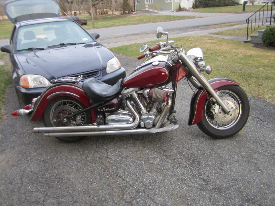
This week the snow is gone and it's been warm, but I decided to take my old friend out for the first ride of the year and not hide in the shop on Sunday. The only day I can spend in my shop.


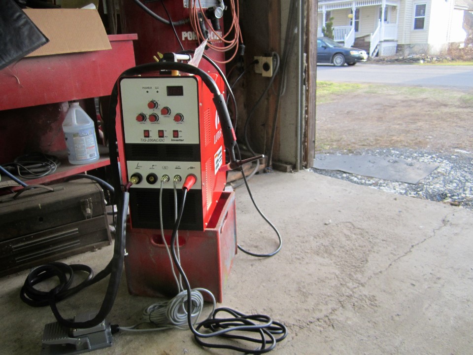
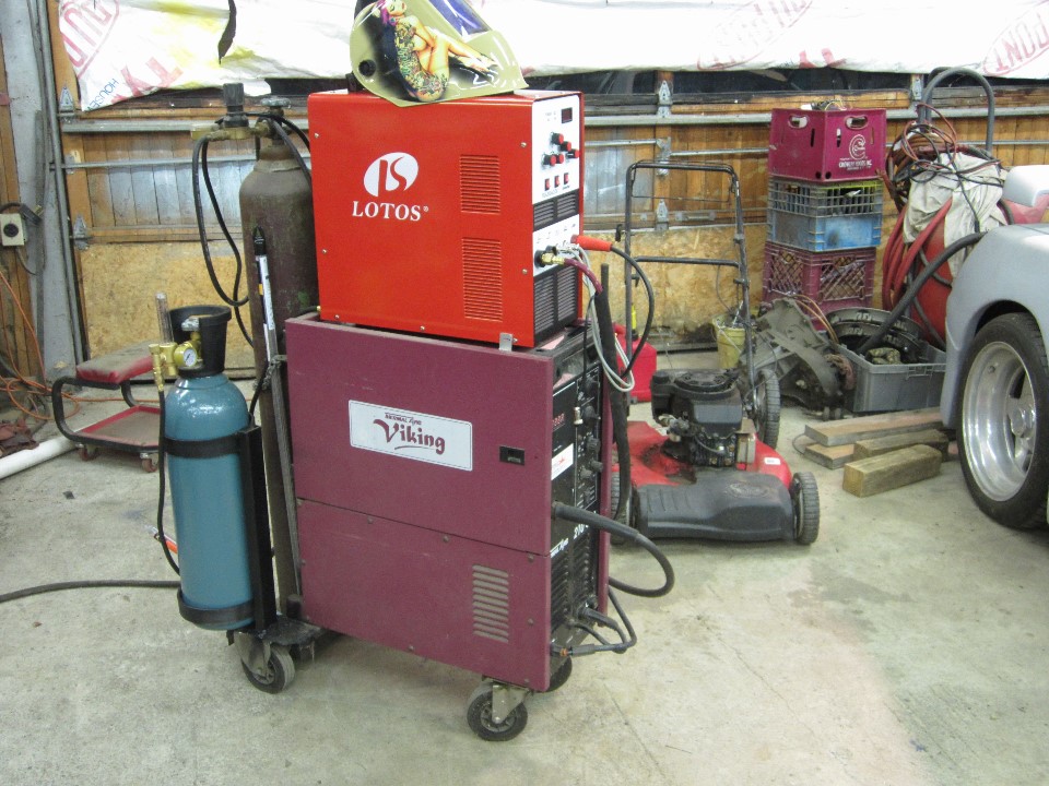
I bought this tig welder for my shop. It's a little on on the low end but I think it will be good for hobby use along side my old mig. I have yet to get the tank and some supplies.


So it maybe a month or two before I get back to the Fiero for this year. Updates will be coming soon.

------------------
Sincerely
George

IP: Logged
fierogt4e
Member
Posts: 119
From: up state New York
Registered: Mar 2003


Feedback score: N/A
Leave feedback

Rate this member

Report this Post04-30-2017 01:45 AM Click Here to See the Profile for fierogt4eSend a Private Message to fierogt4eEdit/Delete MessageReply w/QuoteDirect Link to This Post
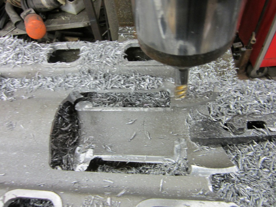
You can see the bottom half of the small tube that runs from the throttle body flange half the way thru the the upper 3500 plenum. Its too small and long for my needs I think. I milled it all away. This big opening will be closed with 1/8” aluminum sheet.
You may also see the six port openings have been enlarged to the full size of the gasket. I will roll the edge later, when cleaning up the welds.


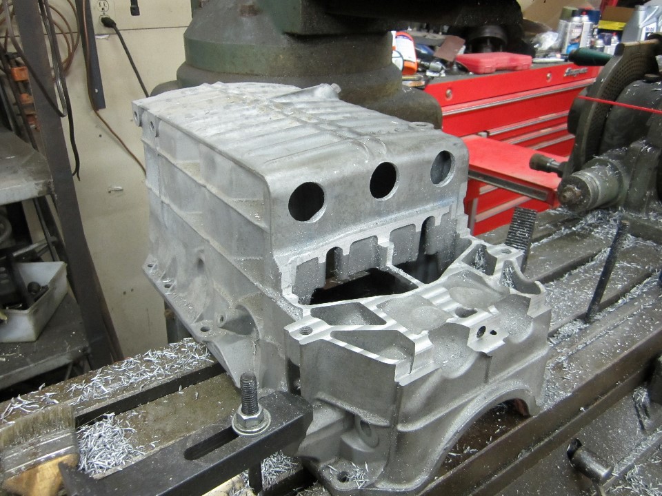
What is this __ doing now? I intend to enlarge the oil pan into the space the exhaust would use. I am leaving that area with the three holes as a dam to help control oil sloshing away from the pickup. I intend to make one-way doors to help by closing off the holes. This oil pan is from an uplander (?) and not the G6,and dose not have the recess for the filter. A little more room there to.


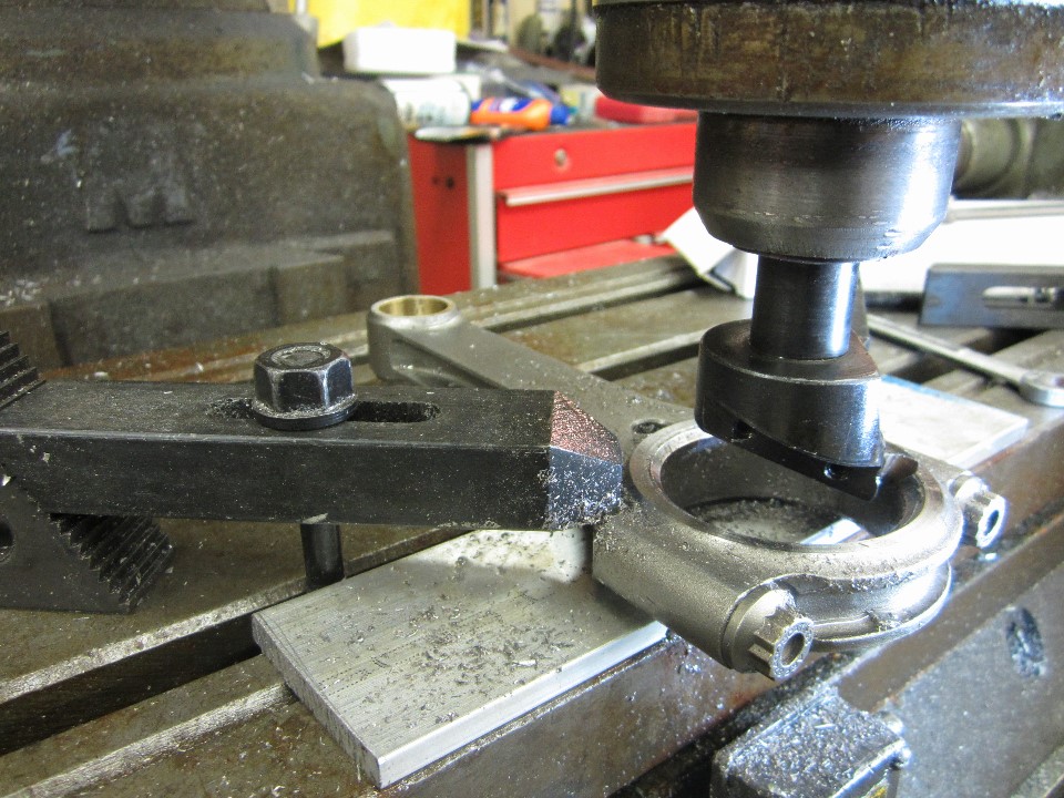
This is one of the 6 1/8” long rods I'm using. The big end I narrowed in a lathe to fit the 3.9 crank. Here I am cutting the chamfers on the bearing to clear the radius on the crank. It needs to be done on both sides of each one. I only did one rod and one bearing as it is a learning effort for me and I may change the way I do some of it for the six I will use in the motor.


------------------
Sincerely
George

https://www.youtube.com/cha...oJ3CMtWvgEok8R-n3XRg

[This message has been edited by fierogt4e (edited 04-30-2017).]

IP: Logged
notwohorns
Member
Posts: 1175
From: greenville, il. usa
Registered: Jul 2009


Feedback score:    (10)
Leave feedback

Rate this member

Report this Post04-30-2017 08:26 PM Click Here to See the Profile for notwohornsSend a Private Message to notwohornsEdit/Delete MessageReply w/QuoteDirect Link to This Post
No
IP: Logged
ericjon262
Member
Posts: 3082
From: everywhere.
Registered: Jan 2010


Feedback score:    (10)
Leave feedback


Total ratings: 66
Rate this member

Report this Post04-30-2017 11:02 PM Click Here to See the Profile for ericjon262Send a Private Message to ericjon262Edit/Delete MessageReply w/QuoteDirect Link to This Post
Looking good, I modified my 3500 intake similar to how I think you are doing you

here you can see the finished product, with a 75mm LS1 throttle body installed.


Edit:

LOL, posted the same pics twice in one thread... oops...

------------------
"I am not what you so glibly call to be a civilized man. I have broken with society for reasons which I alone am able to appreciate. I am therefore not subject to it's stupid laws, and I ask you to never allude to them in my presence again."

"The day I tried to live, I stole a thousand beggars' change and gave it to the rich."
https://www.fiero.nl/forum/Forum2/HTML/119122.html

[This message has been edited by ericjon262 (edited 05-01-2017).]

IP: Logged
slowv8fiero
Member
Posts: 32
From:
Registered: Apr 2017


Feedback score: N/A
Leave feedback

User Banned

Report this Post05-01-2017 12:26 PM Click Here to See the Profile for slowv8fieroSend a Private Message to slowv8fieroEdit/Delete MessageReply w/QuoteDirect Link to This Post
pending on how this works out, i might have you lots of pedophiles here mod my upper intake too.

[This message has been edited by slowv8fiero (edited 05-29-2017).]

IP: Logged
fierogt4e
Member
Posts: 119
From: up state New York
Registered: Mar 2003


Feedback score: N/A
Leave feedback

Rate this member

Report this Post05-01-2017 10:27 PM Click Here to See the Profile for fierogt4eSend a Private Message to fierogt4eEdit/Delete MessageReply w/QuoteDirect Link to This Post


Notwohorns ; NO (???) No to which part?


ericjon262
Nice to see you here again. The info and pics of your manifold is why I decided to cut the bottom away to get to the tube inside.

I am also watching your MS3X install as I think this is the way I will be going. The 6 coils, sequential injection, knock censer, flex fuel, and so on, will be needed to help the big cam, long rod, motor run smother at lower RPMs.

slowv8fiero
Welcome to the forum. Have you been lurking ( just reading and not posting, not an insult) or did you just find us? Are you some what local to me? A slow V8 Fiero, hmm, interesting, tell us about it.

------------------
Sincerely
George

https://www.youtube.com/cha...oJ3CMtWvgEok8R-n3XRg

IP: Logged
ericjon262
Member
Posts: 3082
From: everywhere.
Registered: Jan 2010


Feedback score:    (10)
Leave feedback


Total ratings: 66
Rate this member

Report this Post05-01-2017 11:29 PM Click Here to See the Profile for ericjon262Send a Private Message to ericjon262Edit/Delete MessageReply w/QuoteDirect Link to This Post
 
quote
Originally posted by fierogt4e:
ericjon262
Nice to see you here again. The info and pics of your manifold is why I decided to cut the bottom away to get to the tube inside.

I am also watching your MS3X install as I think this is the way I will be going. The 6 coils, sequential injection, knock censer, flex fuel, and so on, will be needed to help the big cam, long rod, motor run smother at lower RPMs.


Lol... I should have re-read the thread... I didn't realize I had already posted that info here. the megasquirt install has been pretty straightforward. knowing what I know now though, I think I would have thrown down the extra $400ish for the MS3 pro instead of the MS3x, mainly because it's a weather resistant case that can be installed anywhere instead of the MS3x which has to be installed in the cabin. my install has been on hold for a bit though, as I'm installing an 88 cradle, and C5 brakes on the car, and have the engine and trans out. I'm pretty excited about all the little stupid things I've fixed so far. it should transform my car and make it much more pleasurable to drive.

I always like seeing progress here, you're clearly not afraid to go all in and build the car the way you want like lots of folks on here. and you have the tools and expertise to do it right. one thing I will recommend, be very careful welding the intake, the shop that welded mine warped the crap out of it and it was a PITA to get flat again.

------------------
"I am not what you so glibly call to be a civilized man. I have broken with society for reasons which I alone am able to appreciate. I am therefore not subject to it's stupid laws, and I ask you to never allude to them in my presence again."

"The day I tried to live, I stole a thousand beggars' change and gave it to the rich."
https://www.fiero.nl/forum/Forum2/HTML/119122.html

IP: Logged
PFF
System Bot
shemdogg
Member
Posts: 1749
From: The Ghetto CA USA
Registered: Apr 2017


Feedback score: N/A
Leave feedback

Rate this member

Report this Post05-02-2017 12:24 AM Click Here to See the Profile for shemdoggSend a Private Message to shemdoggEdit/Delete MessageReply w/QuoteDirect Link to This Post
Very cool thread and mods!

shem
IP: Logged
fierogt4e
Member
Posts: 119
From: up state New York
Registered: Mar 2003


Feedback score: N/A
Leave feedback

Rate this member

Report this Post05-17-2017 11:54 PM Click Here to See the Profile for fierogt4eSend a Private Message to fierogt4eEdit/Delete MessageReply w/QuoteDirect Link to This Post

I have my tig setup for the most part. It said not to stack it do to a chance of it falling. I stacked it. I need the floor space. But you can see one of the little clips in the lower right hand corner to support it. I made the rings to build the rack the tank is in. It's back far enough to open the wire spool door on my old mig, to more than 90deg. to change spools easily.


I added this cable-tree so I could get to all the different cables, keep them neat, and off the floor when not in use. It also has a clip to brace the tig in the upper rear. And one is in the lower front that keeps it in place.


I'm all set to start building. THEN... it sh_t the bed!!! completely dead, nothing, junk. So back it goes. I guess I need to go a step or two up in tigs. What are you using???

------------------
Sincerely
George

https://www.youtube.com/cha...oJ3CMtWvgEok8R-n3XRg

IP: Logged
ericjon262
Member
Posts: 3082
From: everywhere.
Registered: Jan 2010


Feedback score:    (10)
Leave feedback


Total ratings: 66
Rate this member

Report this Post05-18-2017 03:09 PM Click Here to See the Profile for ericjon262Send a Private Message to ericjon262Edit/Delete MessageReply w/QuoteDirect Link to This Post
I really like my Miller Diversion 180, but I'm also a TIG novice.
IP: Logged
fierogt4e
Member
Posts: 119
From: up state New York
Registered: Mar 2003


Feedback score: N/A
Leave feedback

Rate this member

Report this Post08-22-2017 12:45 AM Click Here to See the Profile for fierogt4eSend a Private Message to fierogt4eEdit/Delete MessageReply w/QuoteDirect Link to This Post
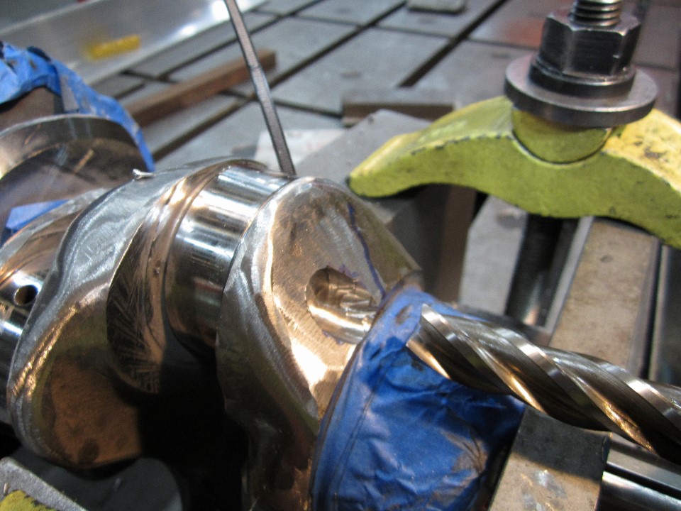
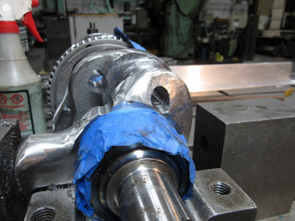
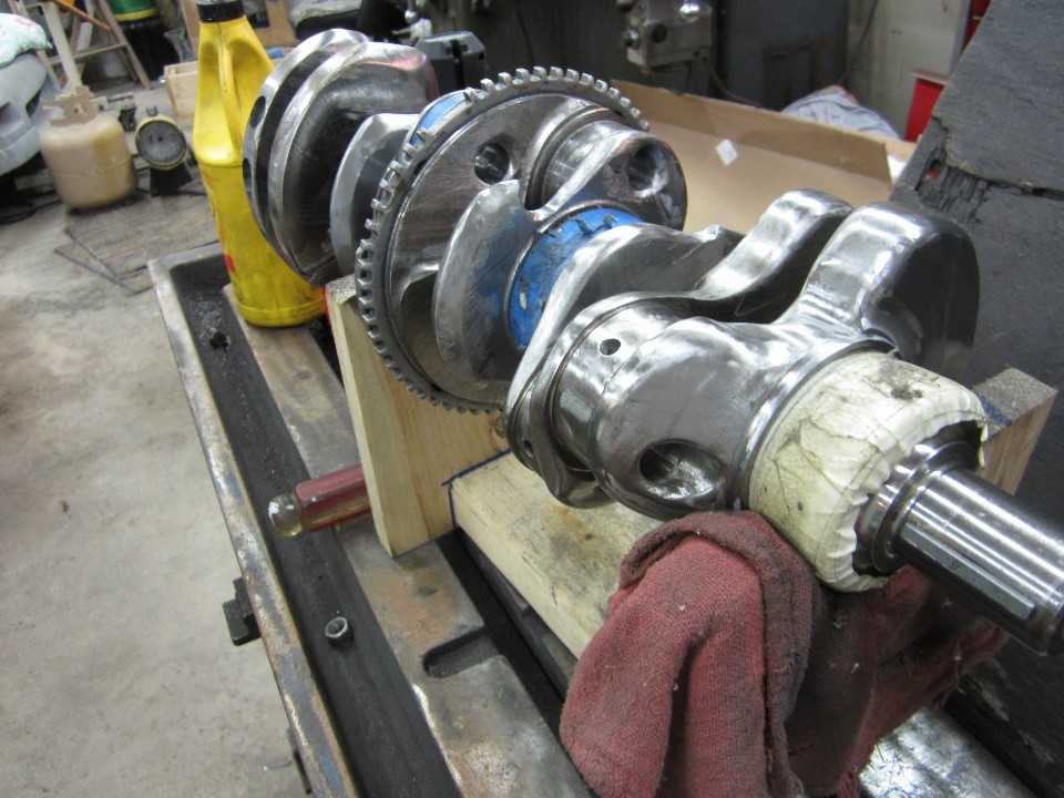
lately I've been working on the crank. Knife edging the counter weights leading edge, radius the trailing end, drilling the rod journals, milling of excess materiel, and polishing. When I'm done with this I can finely get the journals ground down from 2.250 to 2.000 for the new rods. The pistons must be notched, polished and balanced before I can have the crank balanced, and the heads must be done before I can do the pistons.


Well I've thought I was done the the lightening and polishing of the crank a few time. But after studying it for awhile, I did a little more, then studying it for awhile I did a little more, then...
Now it may be time to get the journals ground down at the crank grinder.

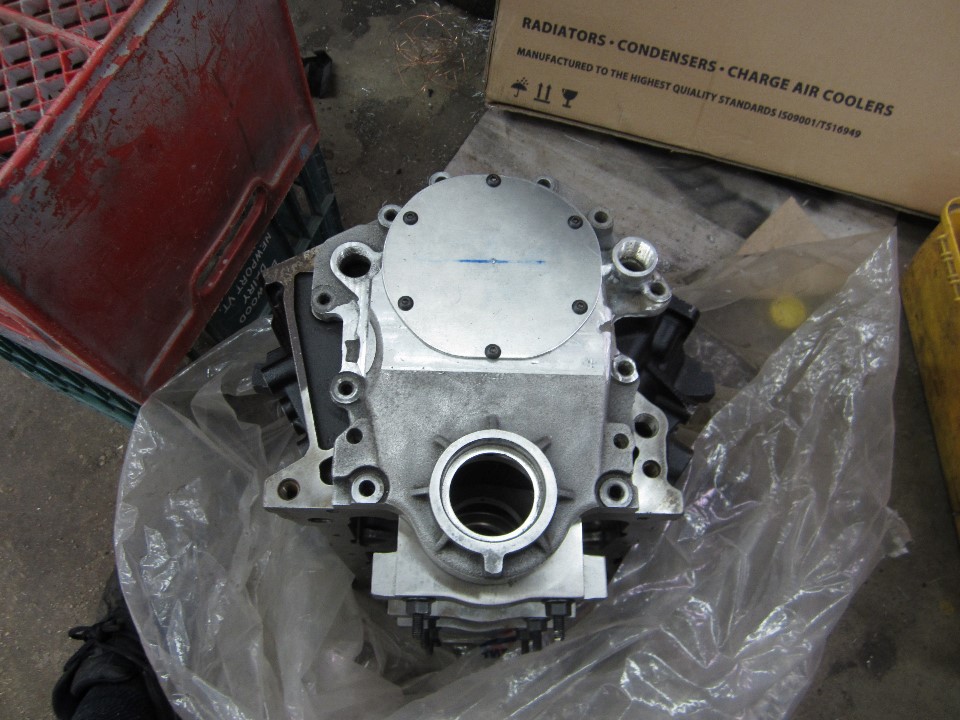
I tend to jump around on the different parts depending on machines I can get on at work. What I can get metal for. Or boredom. And the hard one, money enough for.
This is a timing cover for remote water pump I have been working on. I will most likely get stainless button head to re place the black oxide ones in this fit-up.
It's the stock cover with all the extra stuff milled off and bungs welded on for ¾ pipe tap. An 1/8 inch thick plate covers the opening.


------------------
Sincerely
George

https://www.youtube.com/cha...oJ3CMtWvgEok8R-n3XRg

[This message has been edited by fierogt4e (edited 08-22-2017).]

IP: Logged
ericjon262
Member
Posts: 3082
From: everywhere.
Registered: Jan 2010


Feedback score:    (10)
Leave feedback


Total ratings: 66
Rate this member

Report this Post08-22-2017 11:26 AM Click Here to See the Profile for ericjon262Send a Private Message to ericjon262Edit/Delete MessageReply w/QuoteDirect Link to This Post
I'm loving this build, you're going all in all over, I'm excited to see how the crank will look once you're done with it!

------------------
"I am not what you so glibly call to be a civilized man. I have broken with society for reasons which I alone am able to appreciate. I am therefore not subject to it's stupid laws, and I ask you to never allude to them in my presence again."

"The day I tried to live, I stole a thousand beggars' change and gave it to the rich."
https://www.fiero.nl/forum/Forum2/HTML/119122.html

IP: Logged
solotwo
Member
Posts: 5374
From: Grand Rapids, MI. USA
Registered: Jun 2002


Feedback score:    (9)
Leave feedback


Total ratings: 62
Rate this member

Report this Post08-26-2017 11:14 PM Click Here to See the Profile for solotwoSend a Private Message to solotwoEdit/Delete MessageReply w/QuoteDirect Link to This Post
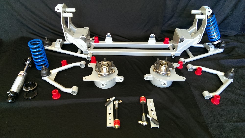
Hello enjoy your mods to your car. I have a question about the arraut front suspension. Have they addressed the weak point in the 84-87 front suspension? The tube the upper long bolt goes thru. That part is softer than the hardened bolts and the holes "egg out". I have had to replace the front cross member twice now on my 87.

Keep posting your doing a great job!
IP: Logged
fierogt4e
Member
Posts: 119
From: up state New York
Registered: Mar 2003


Feedback score: N/A
Leave feedback

Rate this member

Report this Post08-27-2017 02:17 AM Click Here to See the Profile for fierogt4eSend a Private Message to fierogt4eEdit/Delete MessageReply w/QuoteDirect Link to This Post
solotwo
Are you using a stock stamped steel cross member?
I run the complete solo kit with the fabricated cross member. Adjustments are made with a pair of rod ends the bolt passes through for the upper “A” arm inner mounts not tubes..


------------------
Sincerely
George

https://www.youtube.com/cha...oJ3CMtWvgEok8R-n3XRg

[This message has been edited by fierogt4e (edited 08-27-2017).]

IP: Logged
fierogt4e
Member
Posts: 119
From: up state New York
Registered: Mar 2003


Feedback score: N/A
Leave feedback

Rate this member

Report this Post10-03-2017 12:19 AM Click Here to See the Profile for fierogt4eSend a Private Message to fierogt4eEdit/Delete MessageReply w/QuoteDirect Link to This Post
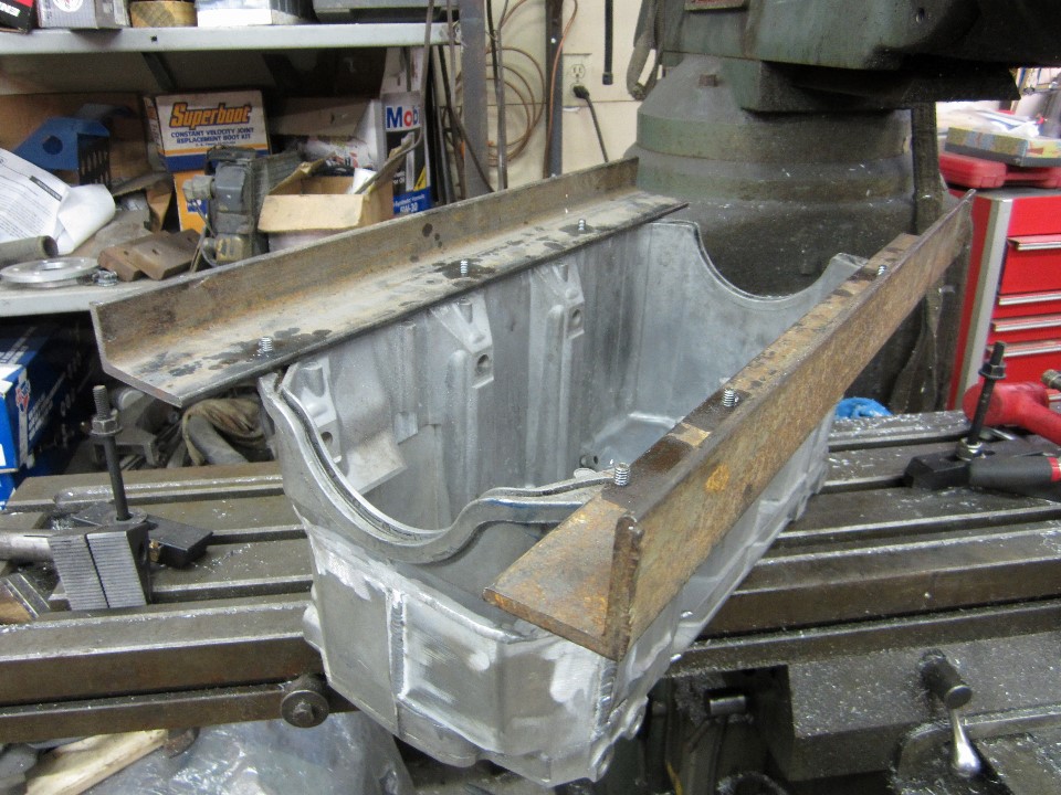
I changed direction on the oil pan, as can be seen here. I cut a section out of a different oil pan to graft onto the pan to create one that is is full depth for the entire length.
There is more work to do on it, but I like how it's coming out.
However should I need to make another one I will use two pans that are exactly the same for construction.

------------------
Sincerely
George

https://www.youtube.com/cha...oJ3CMtWvgEok8R-n3XRg

IP: Logged
fierogt4e
Member
Posts: 119
From: up state New York
Registered: Mar 2003


Feedback score: N/A
Leave feedback

Rate this member

Report this Post10-04-2017 10:52 PM Click Here to See the Profile for fierogt4eSend a Private Message to fierogt4eEdit/Delete MessageReply w/QuoteDirect Link to This Post

The friend I have helping me hot glue (weld) the pan together asked me to open a big hole in the large aluminum plate I had it mounted to so he could weld the inside also. However I use it for many things. So I tapped these angles to try and keep it flat during the inside welding.


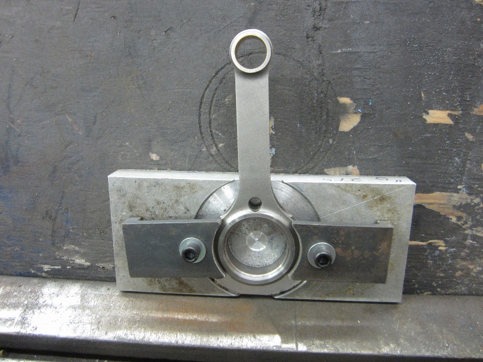
I did not like the way I thinned and chamfered the first rods big end as it had two different setups for each side. This is the fixture I made in the hope I can do both steps on one side at once. That needs to wait for the crank to be done to get side clearance right.

------------------
Sincerely
George

https://www.youtube.com/cha...oJ3CMtWvgEok8R-n3XRg

IP: Logged
Previous Page | Next Page

This topic is 4 pages long:  1   2   3   4 
next newest topic | next oldest topic

All times are ET (US)

Post New Topic  Post A Reply
Hop to:

Contact Us | Back To Main Page

Advertizing on PFF | Fiero Parts Vendors
PFF Merchandise | Fiero Gallery | Ogre's Cave
Real-Time Chat | Fiero Related Auctions on eBay


Copyright (c) 1999, C. Pennock