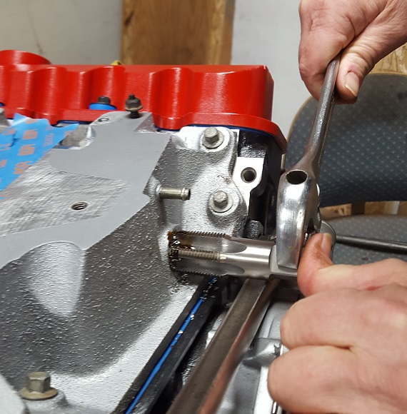
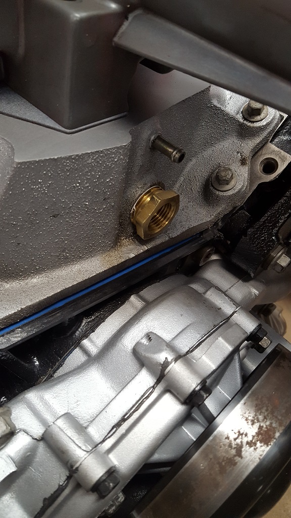
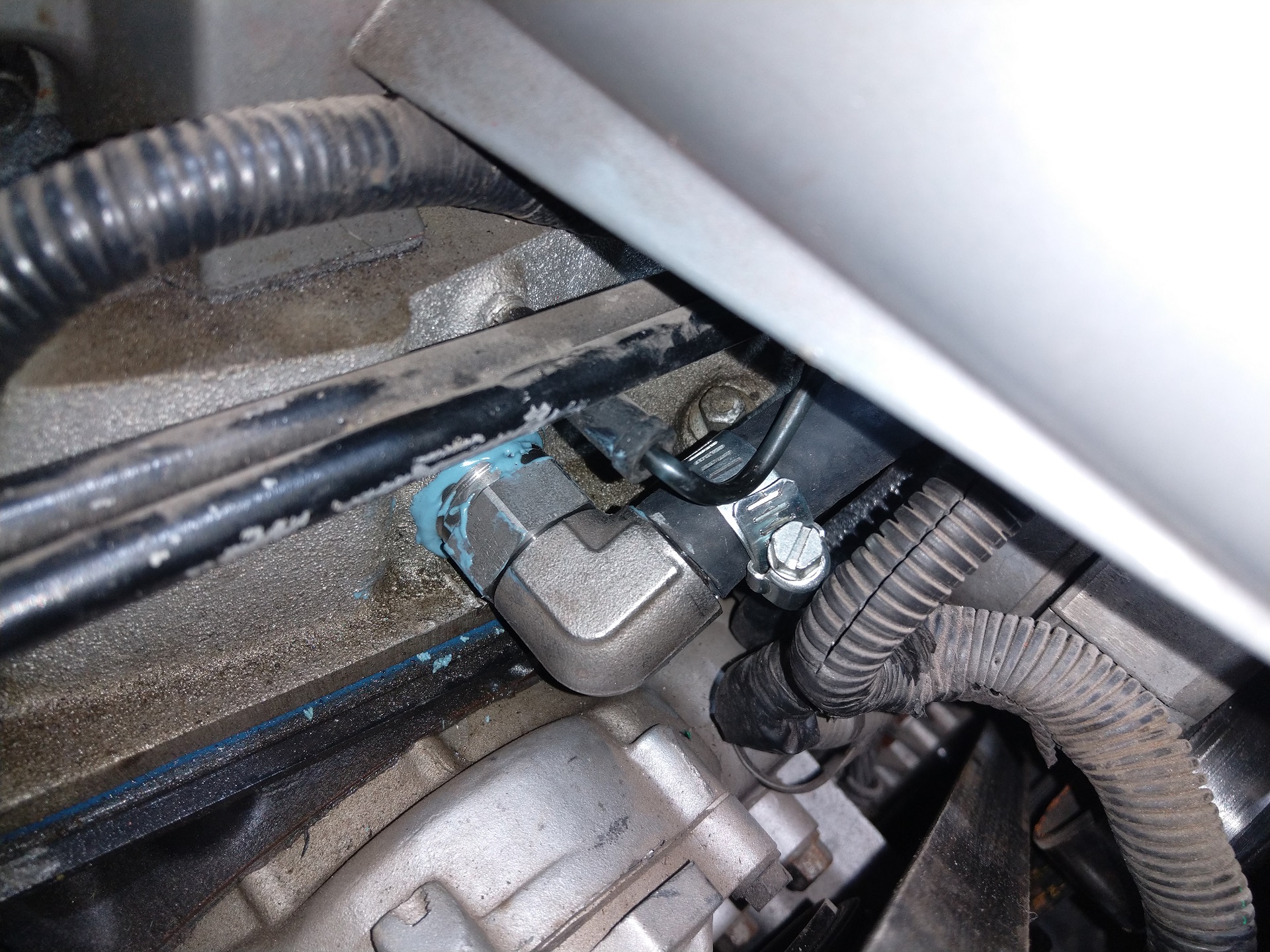
Tapped the LIM and I will be putting the quick coolant connect like what was on many GM cars including the L4 Fiero...That's where I got the idea while pulling the L4 out last night. I have seen a few use a variety of choices. This will give me the opportunity to use stock parts. I will get a pic of the fitting on my next post. You can see that it needs a small adapter. I had to get a hard to find and pricey 3/4 NPT tap.
[This message has been edited by paulsobj (edited 12-04-2023).]
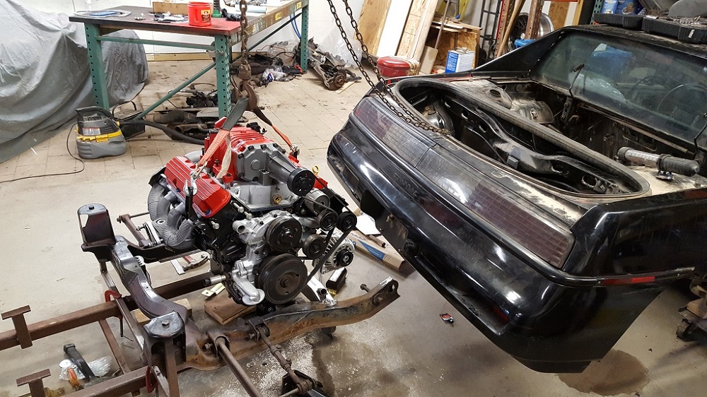
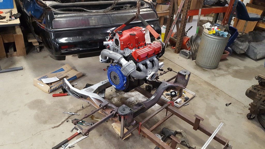
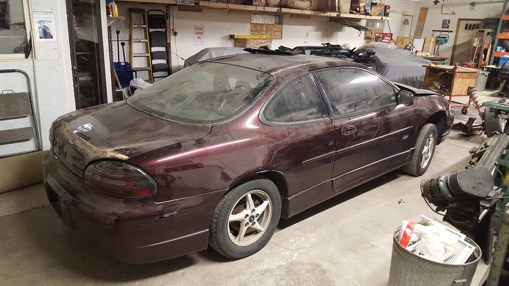
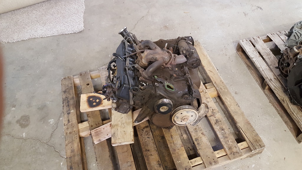
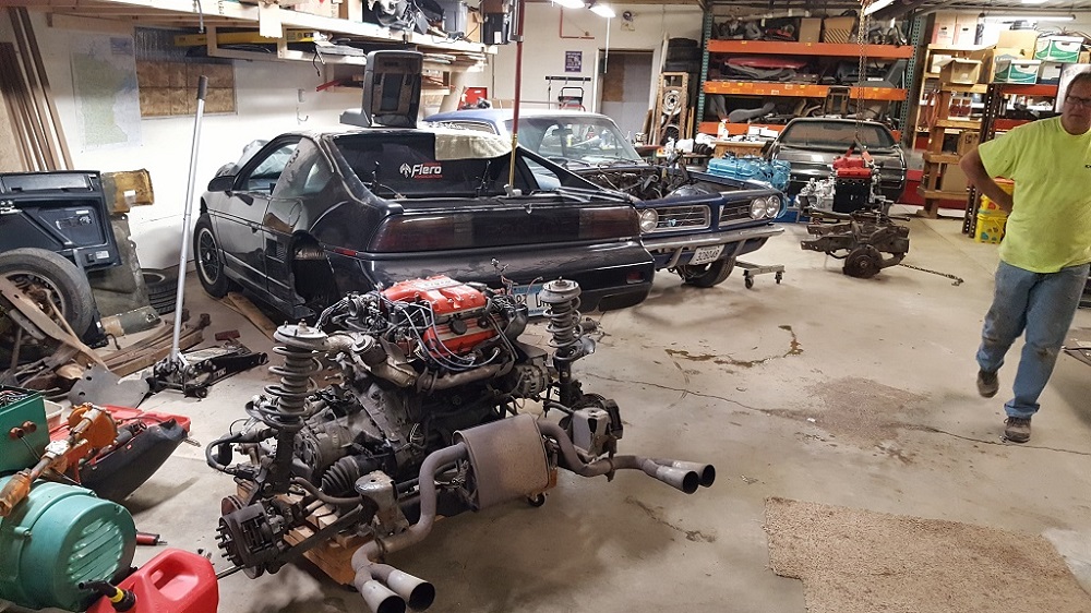
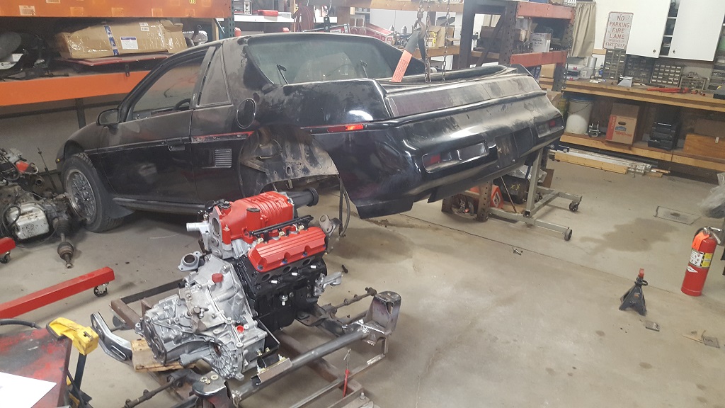
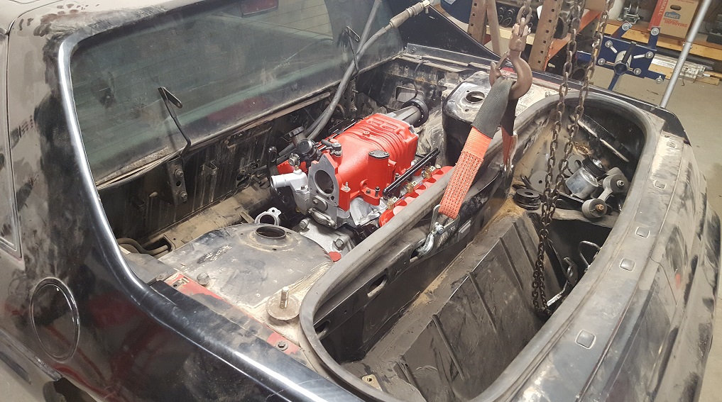
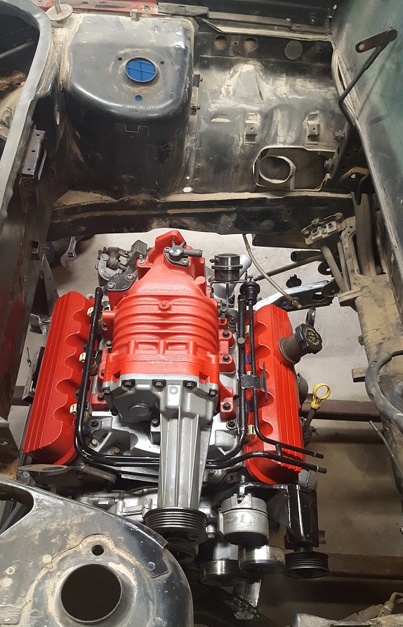
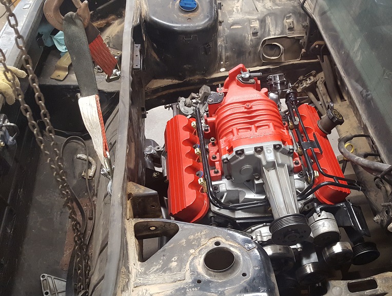
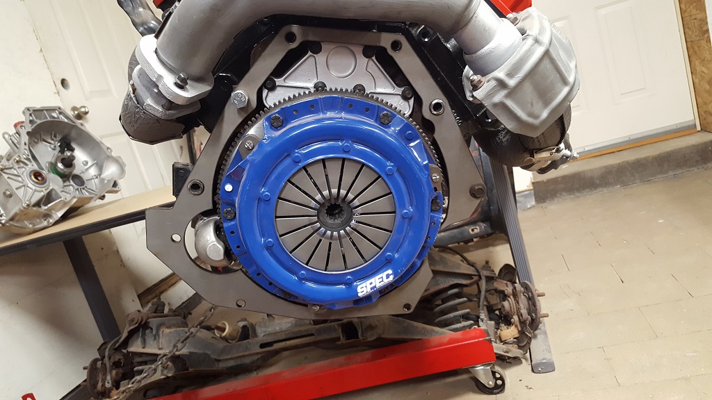
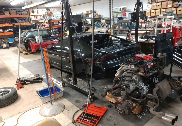
Here is the engine as it is today. I am almost done with assembling it and decided to work on the hubs while I wait for the tensioner/dog bone mount to be made. Then I can make the bracket for the alternator. I bought a 98 GP style as it is easier to make a bracket for.
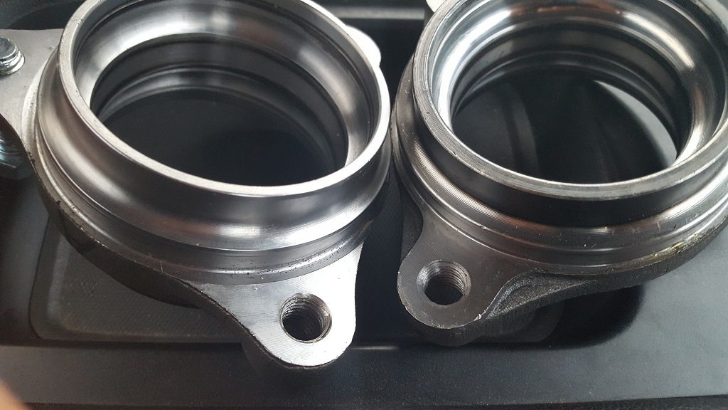
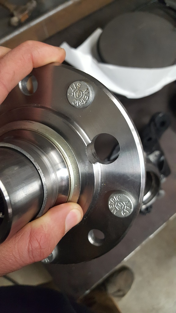
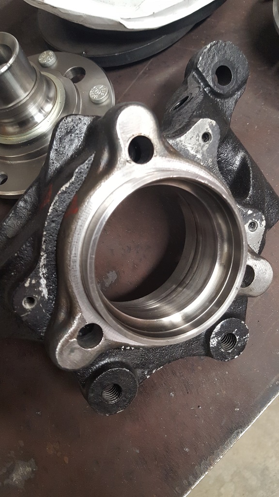
I bought two hubs 513013. I got two different designs but I should be able to make them work. I am doing a simaler machining process that Fieroguru did but I bought 6 low grade bolts to weld into the hub flange. good rule of thumb: The cheaper the bolt the softer the metal and better for welding it in and machining it.
Here you can see the differences. The most concerning it the OD AND ID are both different....
I stopped out at a race shop to look at a few coil over sleeves they had listed for an online auction. I pulled up and see a GTP for sale (looking rough) asking $500. long story short I am getting my already purchased sleeves machined for $10 and traded my GTP for his. I am keeping all the 40th ann stuff too. OH BTW if you find the right recycling center you can sell the OEM cats for these for a pretty penny. I got $65... So now I will be getting another complete 98 GTP. He is selling it to dirt track races who prefer coupes and they dont have to strip the car. Win/Win trade. I bought an alt for a 98 GTP and I bought a EVAP that I accidentally tossed. Both I will have when I get my new GTP... timing... oh well.
While I waited for parts I got busy pulling the interior, HUD, Radio etc. still haven't pulled the seats.
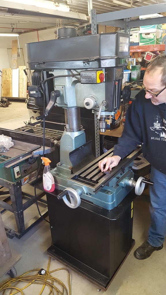
My dad has been looking for sone equipment and we found a good deal on a few things.
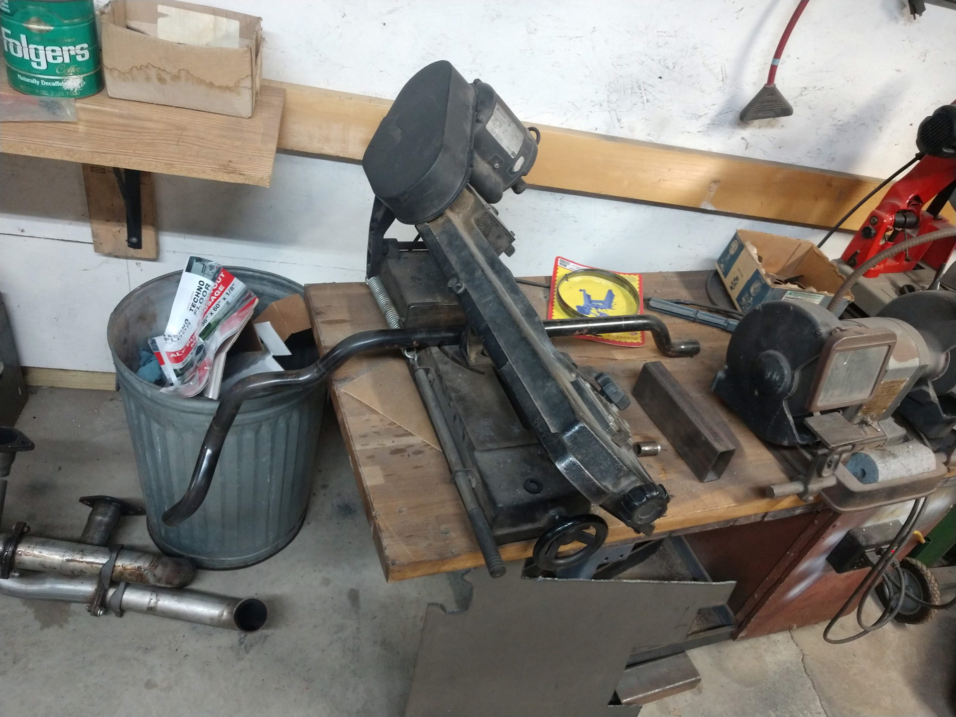
Here is the mill
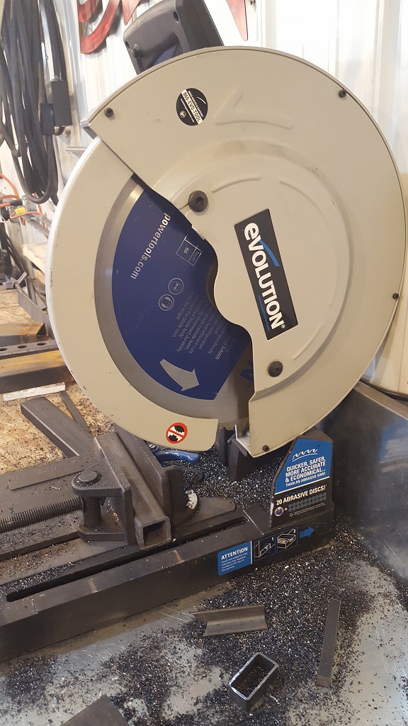
Here is a cold saw. Highly recommend you pick one up when Gov gives you back your money they borrowed at 0% interest. Part # EVO380 around $400 new on Amazon and way better then an abrasive saw.
[This message has been edited by paulsobj (edited 12-04-2023).]
ignorant prodigy Thanks for the comment. I thought I had tons of room. It's easy to fill it up quickly. ha
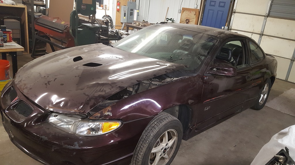
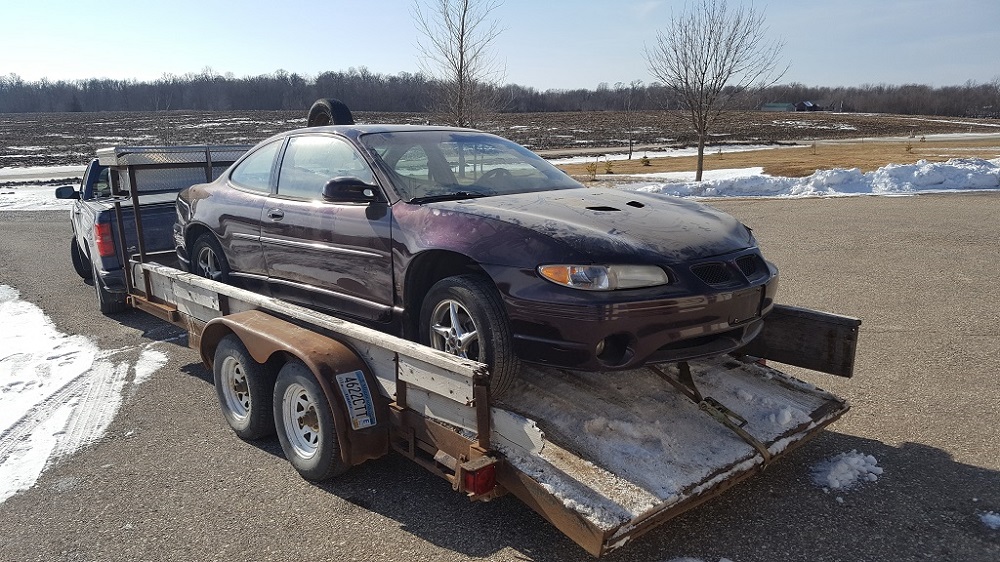
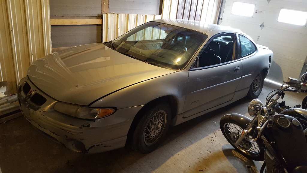
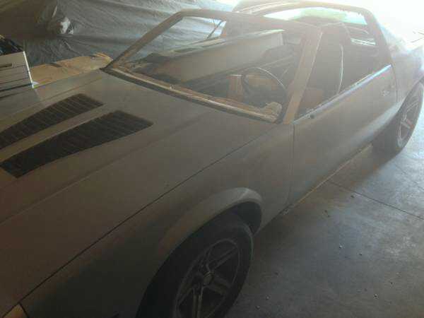
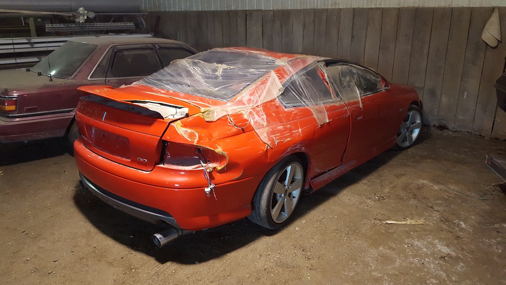
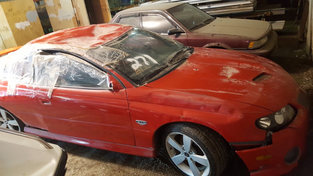
I got the 2002 GTP traded for the 98 GTP today. Here is the car right as we were leaving.
Here is the 98 GTP I traded it for. I am pulling the engine and then listing the car at the race shop. The guy is going to sell it and we will split the cash.
I am bringing the L4 to a auto class at a local High School. I took the class and they teach kids how to tear down and assemble an engine. Its up to the students to find an engine. Some cant afford or have the ability to get one. So I am donating this to them.
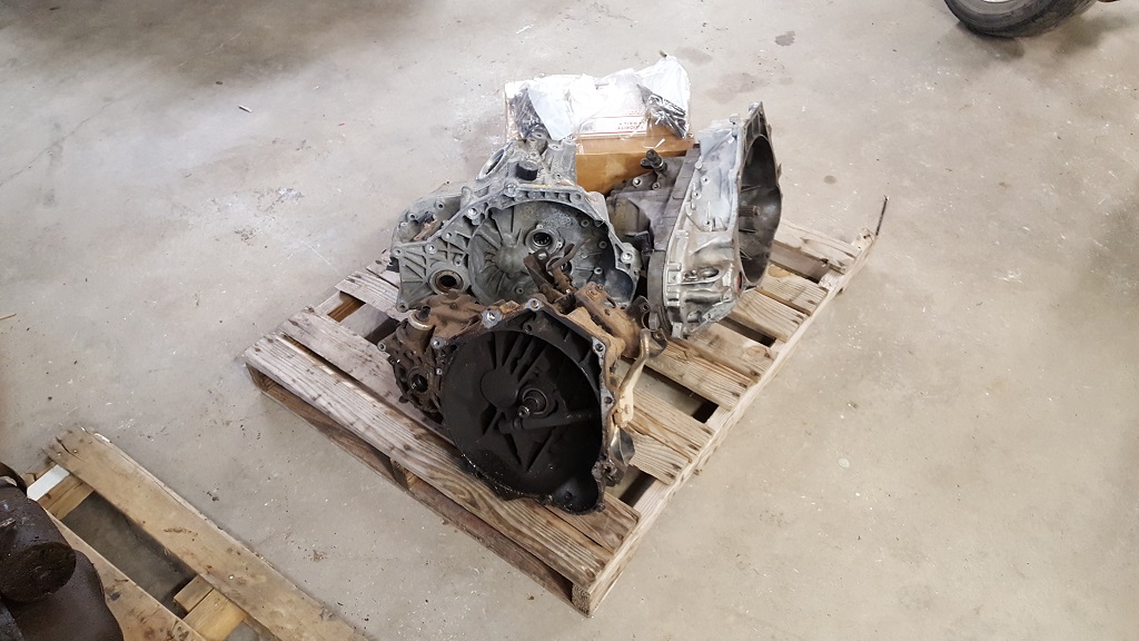
I have too many trans sitting in the heated space. I am moving them to the cold storage for now.
[This message has been edited by paulsobj (edited 12-04-2023).]
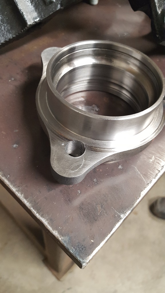
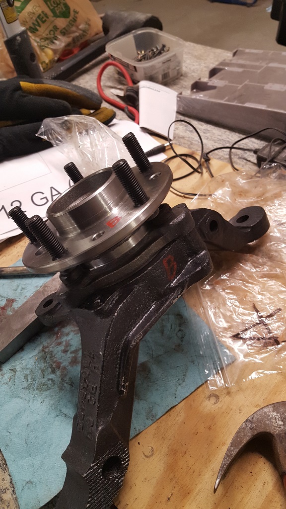
I had a local shop machine the hubs for me. It took 9 hrs for those wondering. I based it off fierogurus 5x4.75 thread. I did buy some bolts to weld into the old holes.
Access hole to install the hub bolts.
I also posted my 88 T-Top in the mall for those looking for a summer ride.
[This message has been edited by paulsobj (edited 12-04-2023).]
I've enjoyed reading this so far. I have a rebodied 88GT with either a 2.8 or 3.1 V6. I'm thinking about dropping in a 3800 and 5 speed down the road, so I'm trying to learn what's involved from threads like this one.
Thank you for sharing. Your clear photos and well written descriptions make it a great read!
Thanks Drewbdo, I try to explain the best I can. I skipped a lot of info on the hub design... I have been busy parting out the 02 and then getting my T-Top ready to sell.
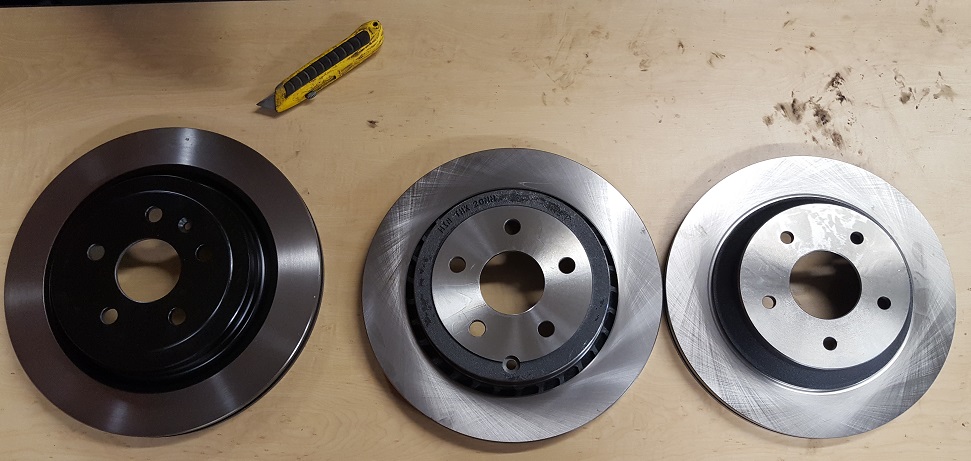
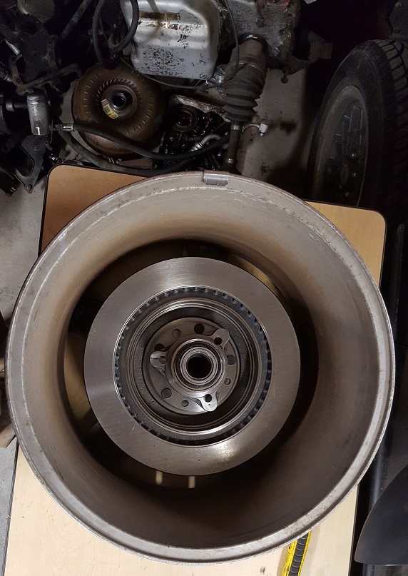
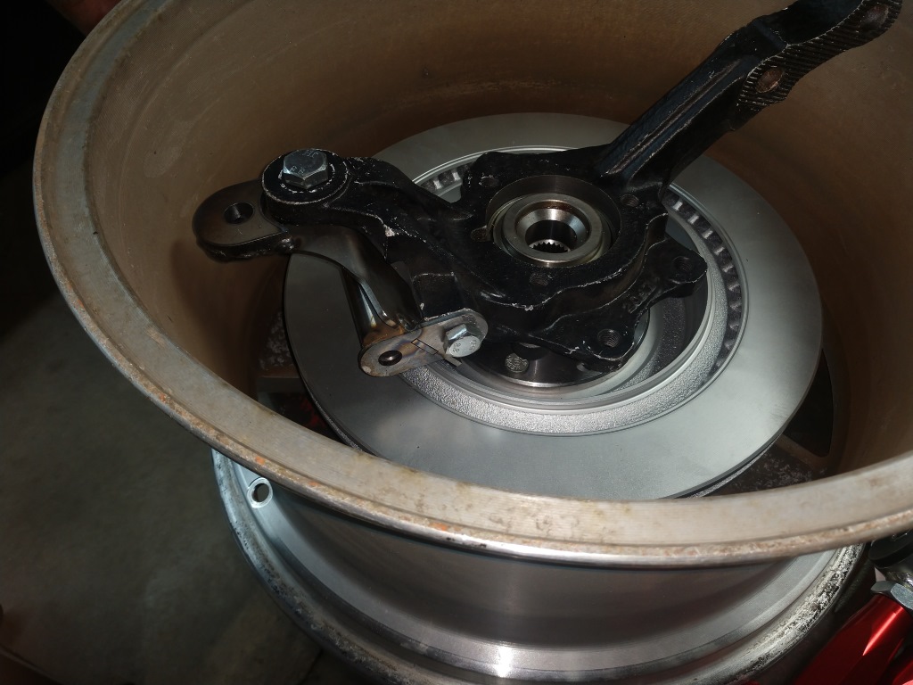
I was able to do a little research on rotors. Here are 3 that I picked up to test. I am not positive but I just might be able to use some 13.3" on this build.
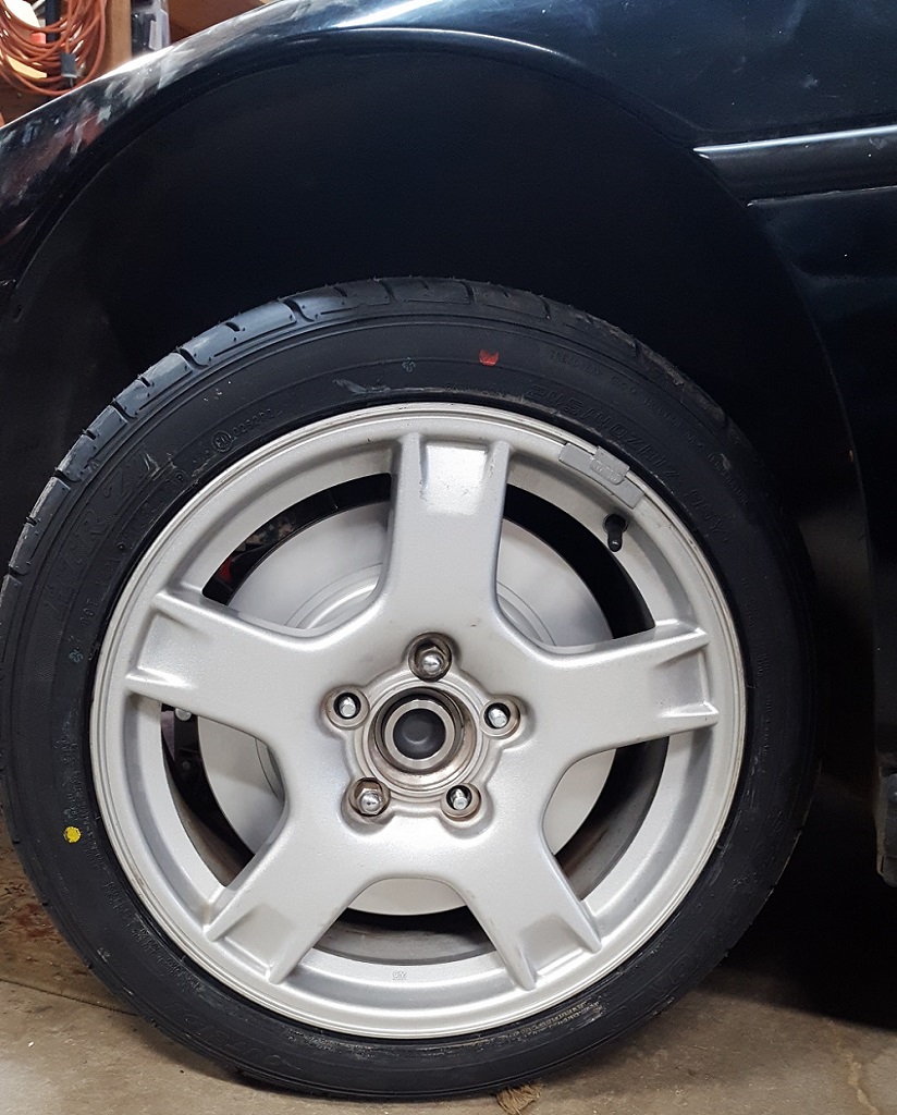
Here it is in the rim.
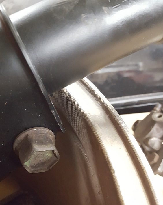
and here is some clearance with the coilover.
I might have to trim a little off just to be safe.
I will have to fab the rotor center a tad to fit. It is a little small. Easier then making centric rings IMO. I am going to order pads and see if it clears the rotor. I may have to get these turned down a little.
[This message has been edited by paulsobj (edited 12-04-2023).]
I was able to get out to the shop yesterday. I received the correct bearing that I ordered from Amazon....
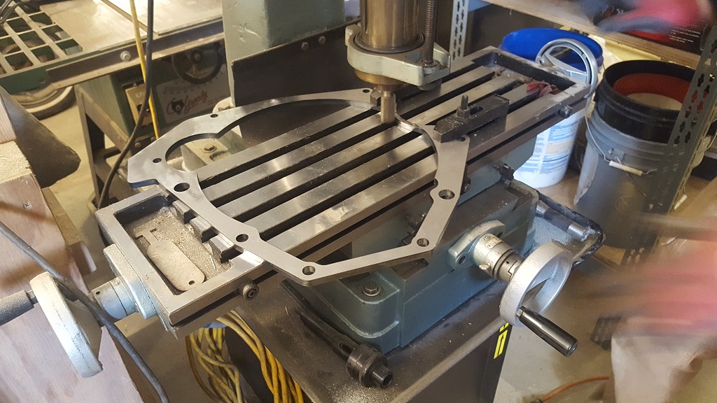
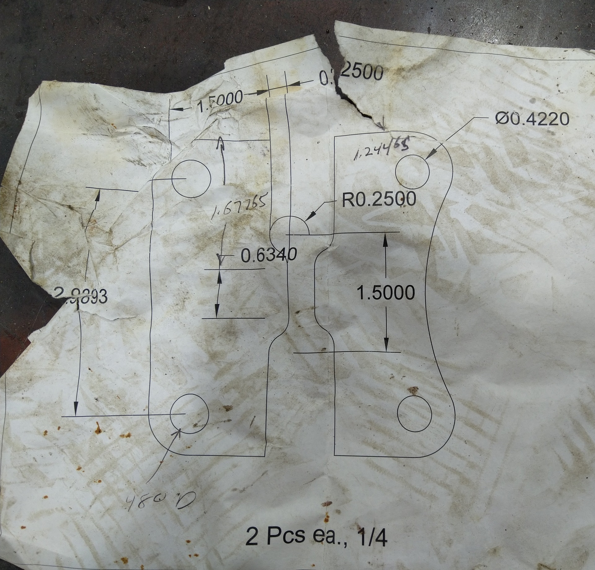
My dad traced the F23 and cut out a construction paper template. He then brought it to work to get scanned by a machine that traces 2D objects and creates CAD files. He then had it cut on 1/4" steel. We brought it to the shop and it was actually very close. We had to move a few holes slightly and only one was noticeably off. We are going to adjust the CAD file and if anyone would like a copy let me know... I can also make more spacers for a yet to be determined price.
I wouldn't mind that CAD file to play around with at work. I will send you a PM with my email address. Great build thread so far!
I'm so glad I found this thread, this is exactly what I am doing except I will be doing a twin turbo set up. I am following this thread for sure. The question I have is, why did you have the hubs machined? Different bearings or to fit the corvette bolt pattern?
Can I also get that cad drawing for the spacer. I want to have one made up for my build.
Good luck.
[This message has been edited by 1fstfiero (edited 03-19-2017).]
I will send out the current version that I have (3). Each time I have cut one I have had the bolt holes adjusted. I could make the tolerances larger for the holes so I have more play. But I prefer a nice tight fit. After two cuts I am sure the third one I cut next will not need any modifications. I am making some design changes to the final spacer. I will get a picture at some point to show what I am talking about. I am adding material to the front (in respect to the car) side of the spacer to make an area to have the trans mount bolted to. As the F23 doesn't have a lot of great spots to mount to.
1fstfiero, I wanted to change the bolt pattern to open up the choices of OEM parts. I now can get a vast selection on rims and rotors that will bolt up. I know there is a better selection of after market rims but I like the ability to hop onto craigslist or go to a junkyard and pickup a rim if I bend one or scratch one. I could have accomplished this with a adapter but I preferred not to go that route. I feel like its more of a band-aid then a fix.
I will post a few updates I have done and what else is going on.
I have been very busy selling and buying a few cars and had to pause the build somewhat as some fierce negotiations were going on for the next years budget. Unfortunately the governor vetoed by proposed budget. The funds were diverted to the down payment for a house.
So in short I sold my 88 T-Top from Hawaii (sadface) for $4100 and bought a 87 IROC 5.7 project for $4000.
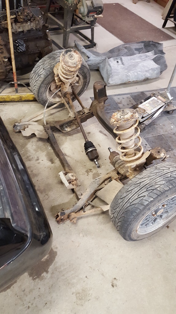
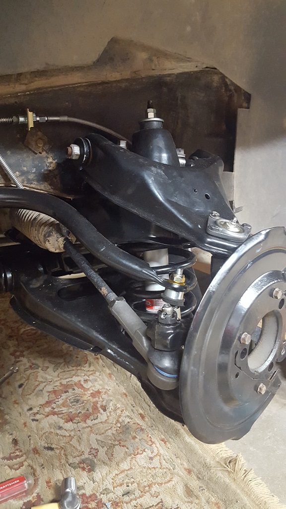
I hit a huge pothole with my truck on my way to pick up the IROC and broke my lief spring. I had to get those fixed and found the front suspension was all messed up so new sway bar links, shocks, 4 ball joints, a hub and about 12hrs labor later...
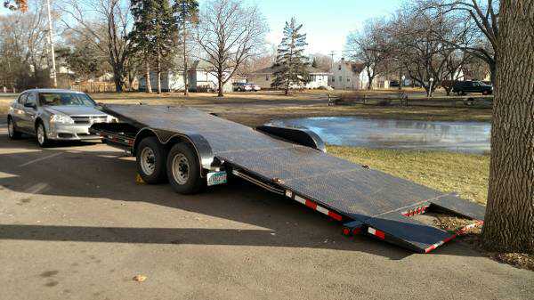
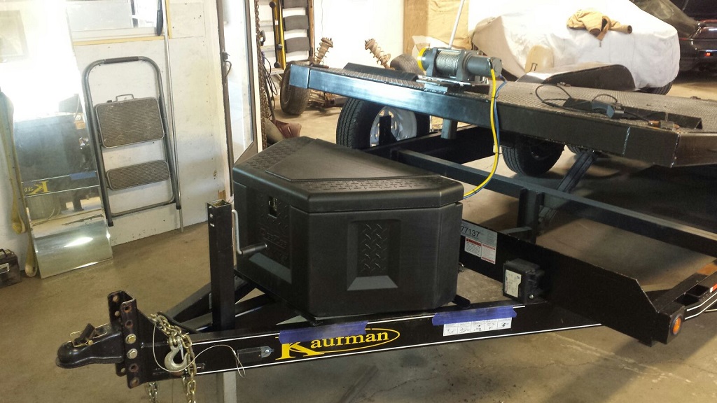
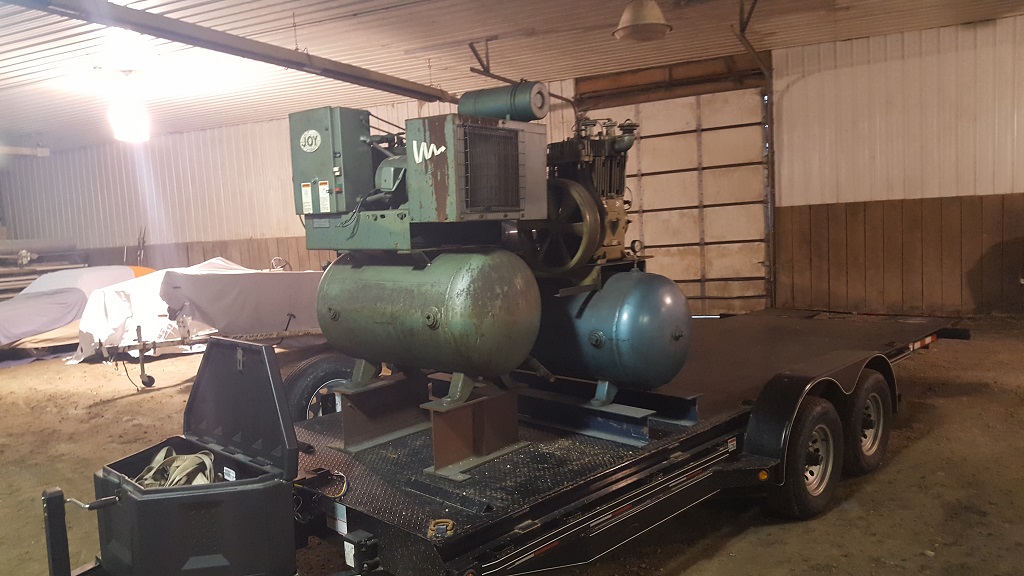
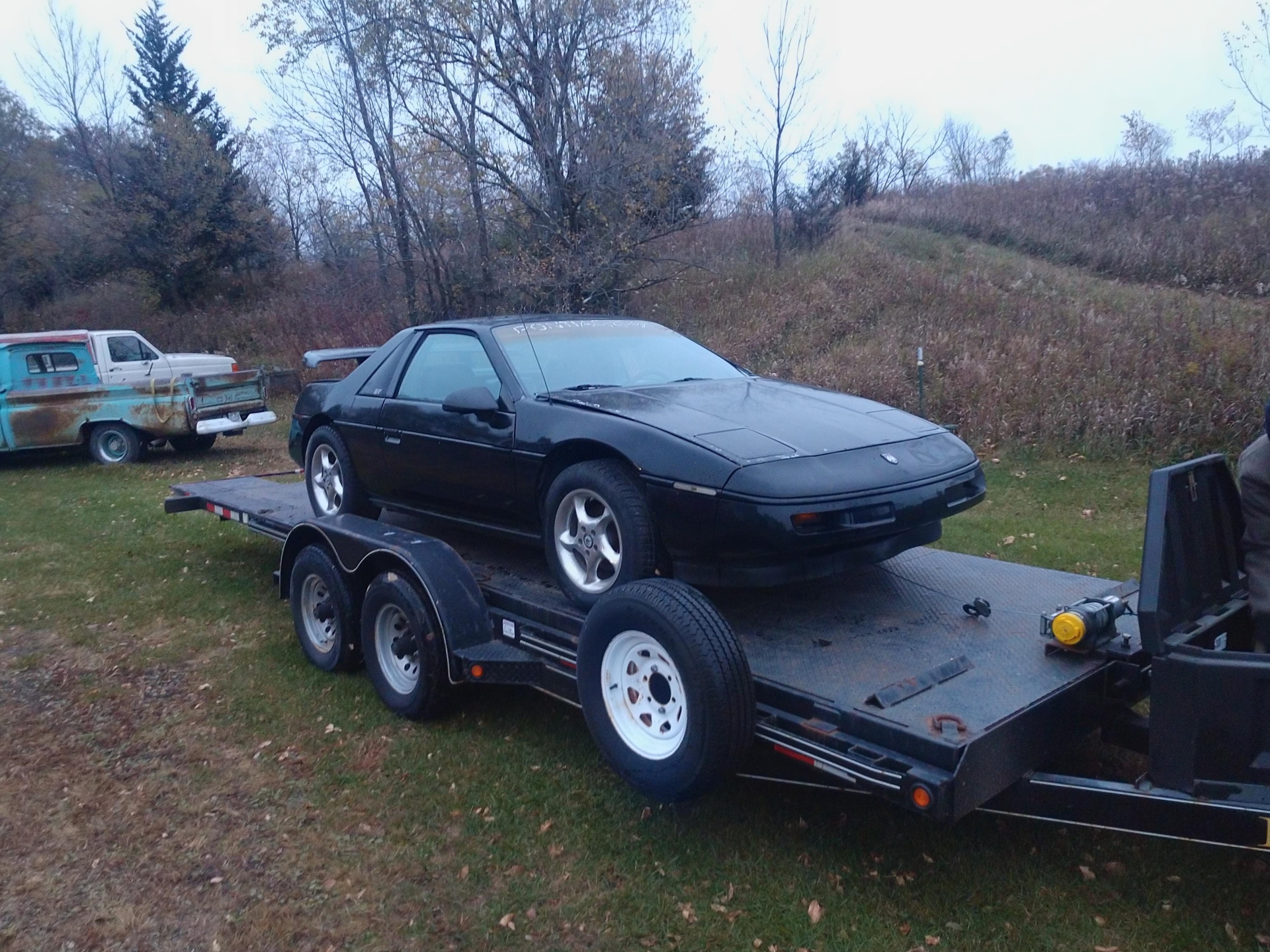
We bought a nice trailer on CL 20' 10k tiltbed and we added a winch and storage container. I used it today to drop off a tenants 60's jag that forgot to pay rent for the last 6 months. We pulled into the driveway unloaded the car and were gone in less then 4 min. I cant tell you how easy and fast this trailer is.
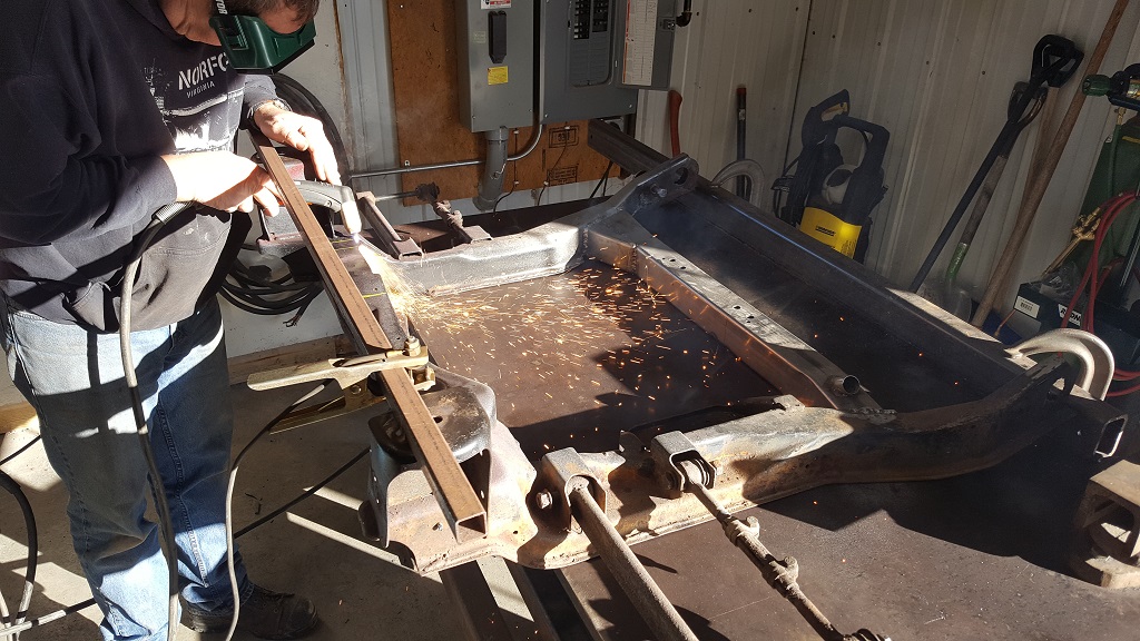
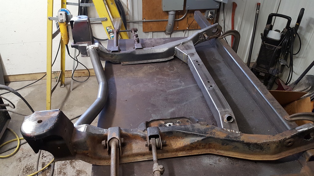
So back to the build. I took out another part of the cradle and replaced it with some scrap tubing that we found.
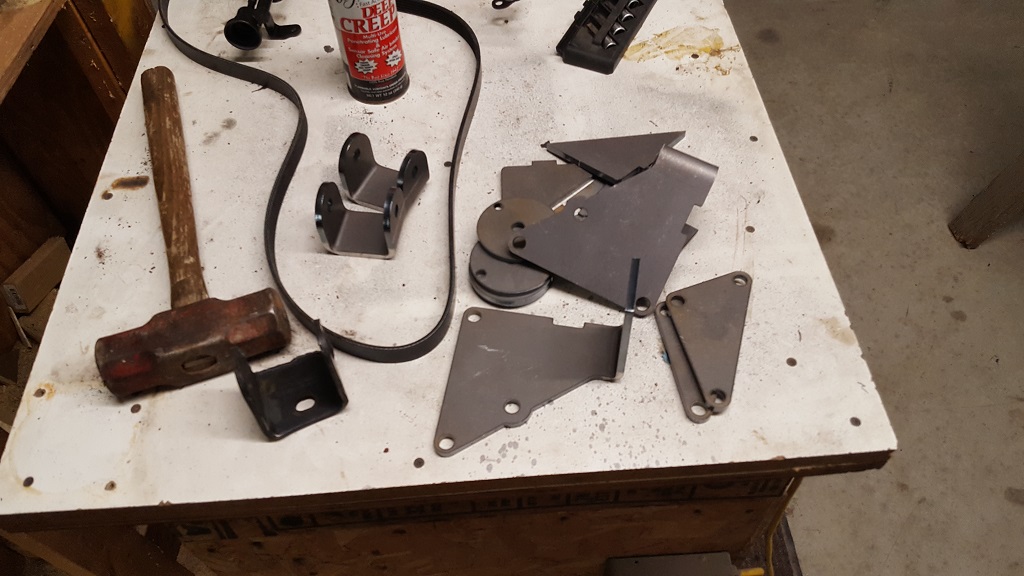
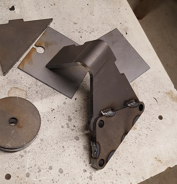
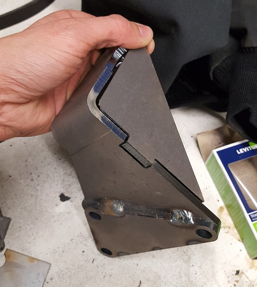
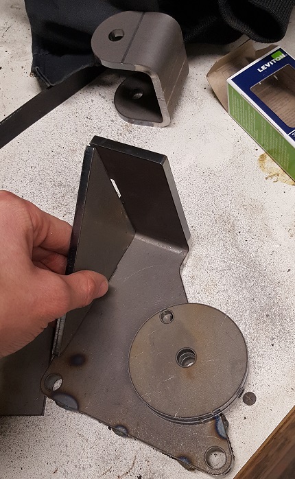
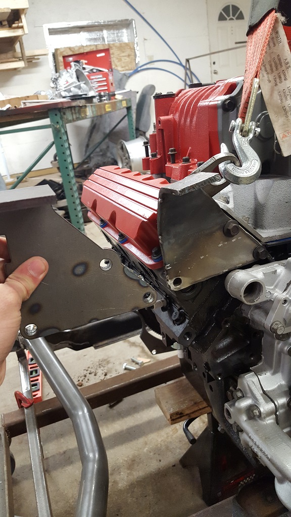
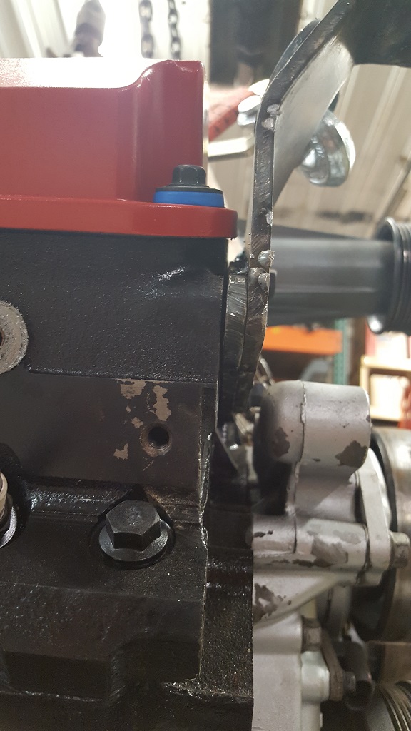
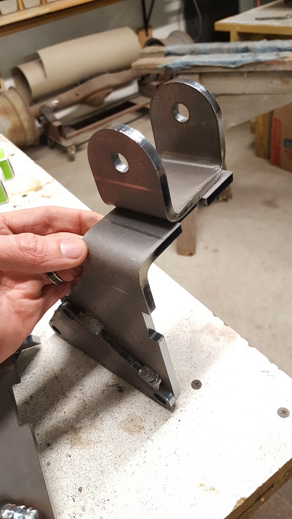
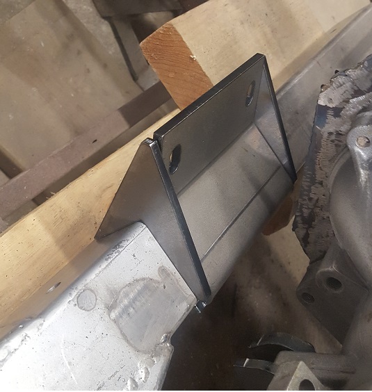
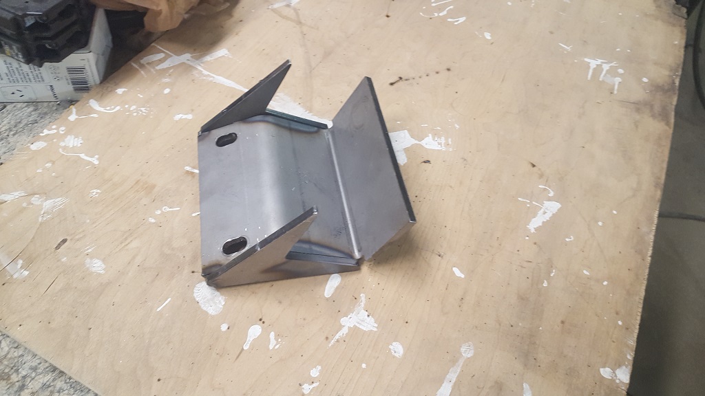
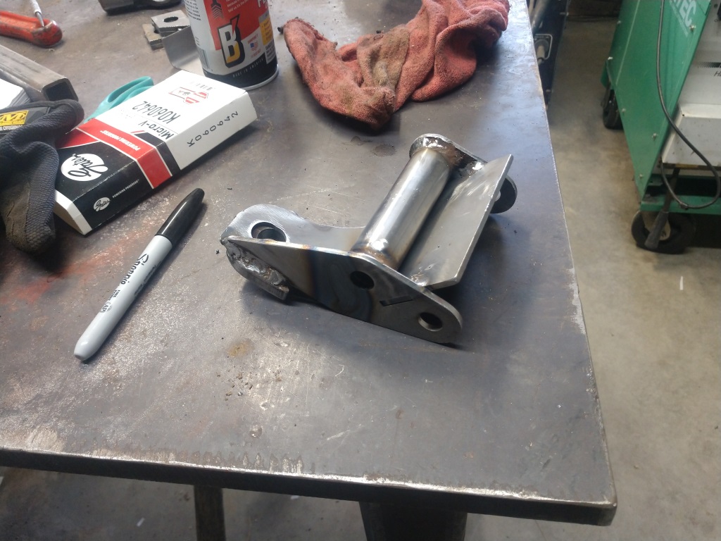
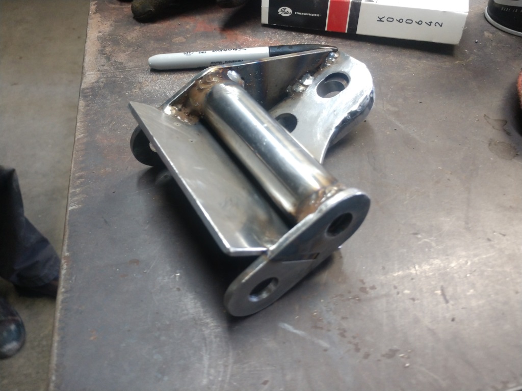
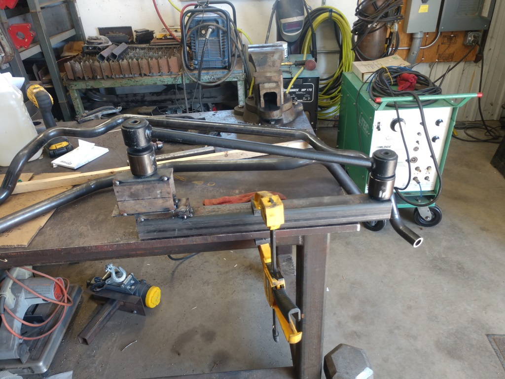
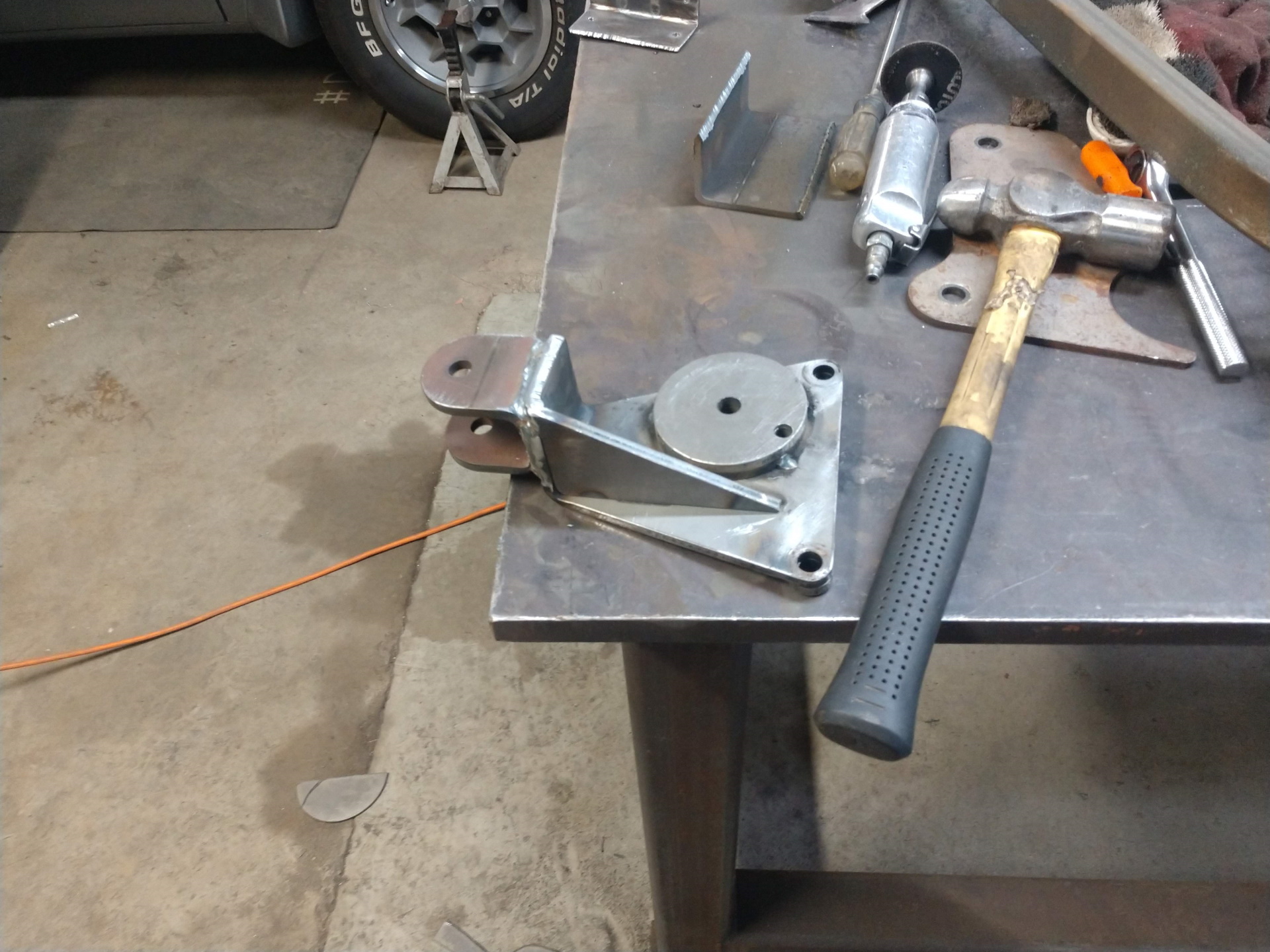
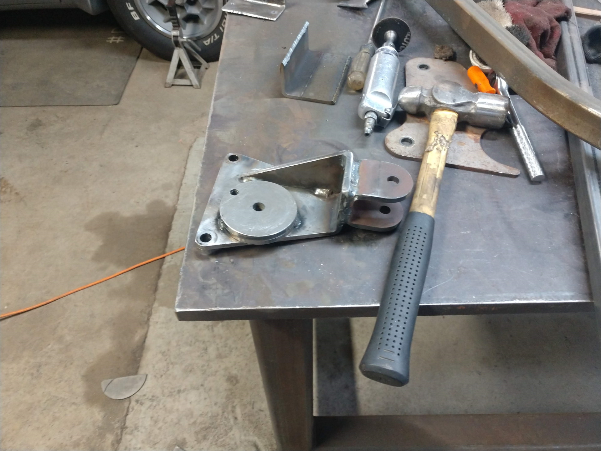
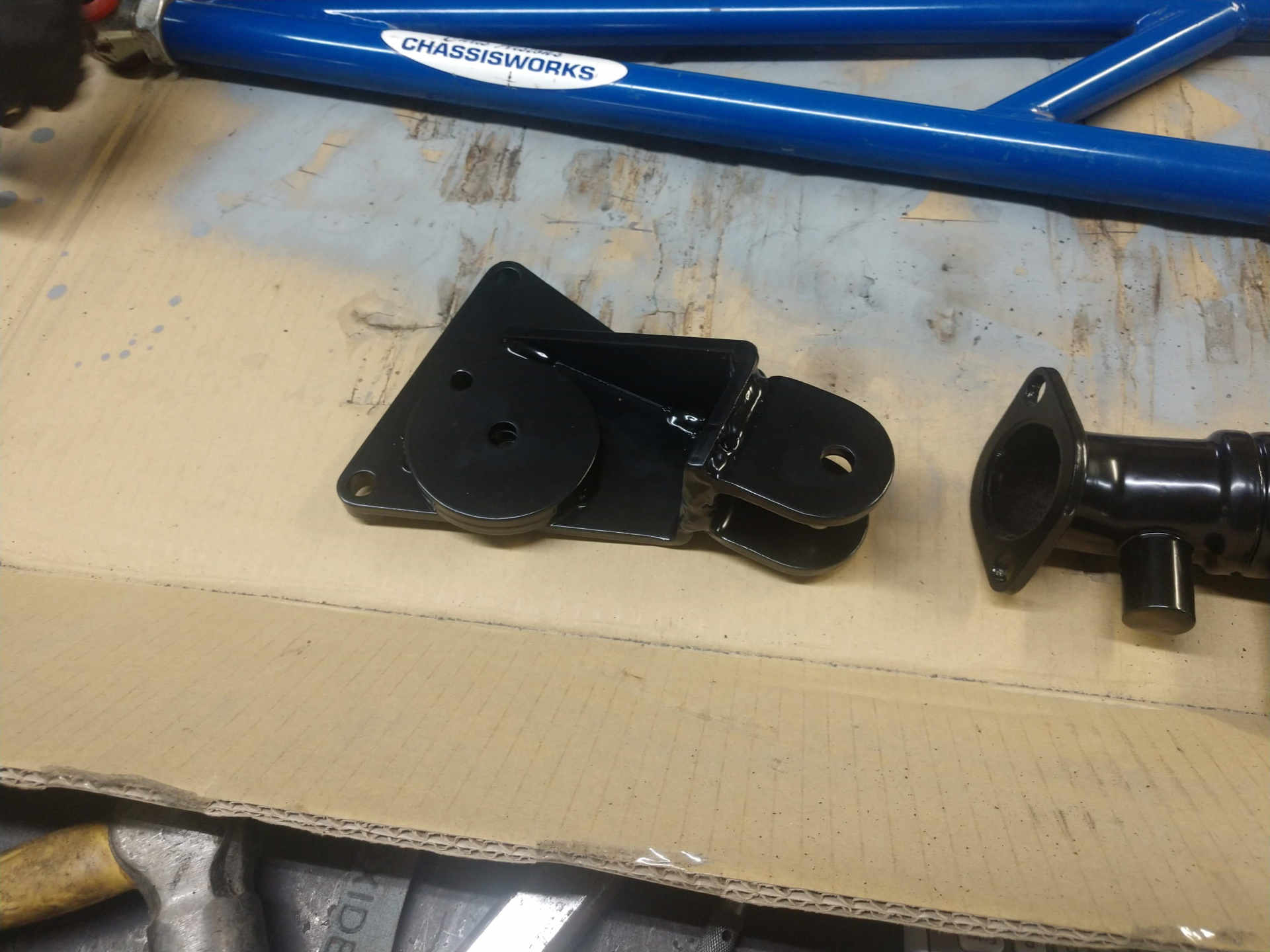
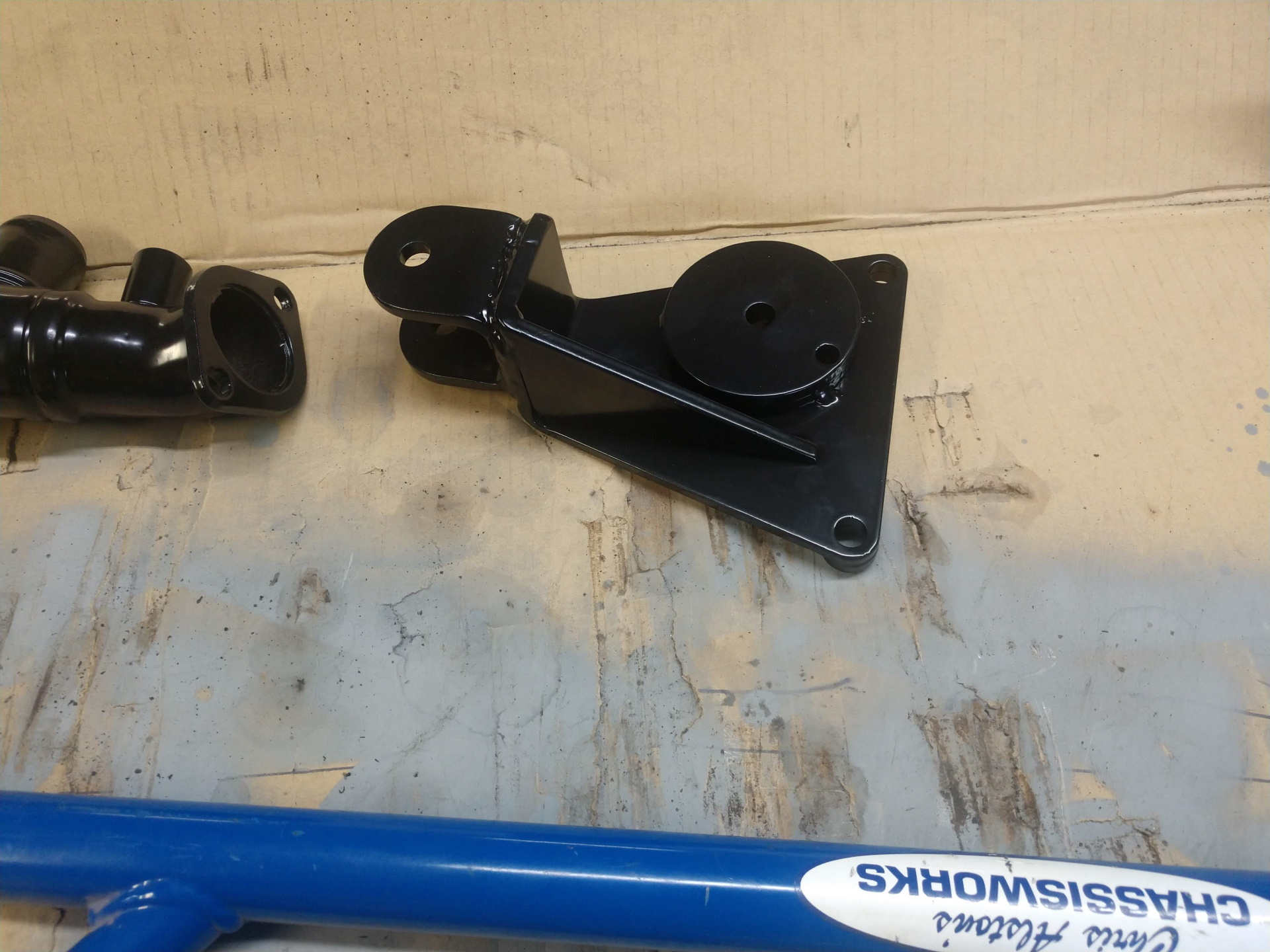
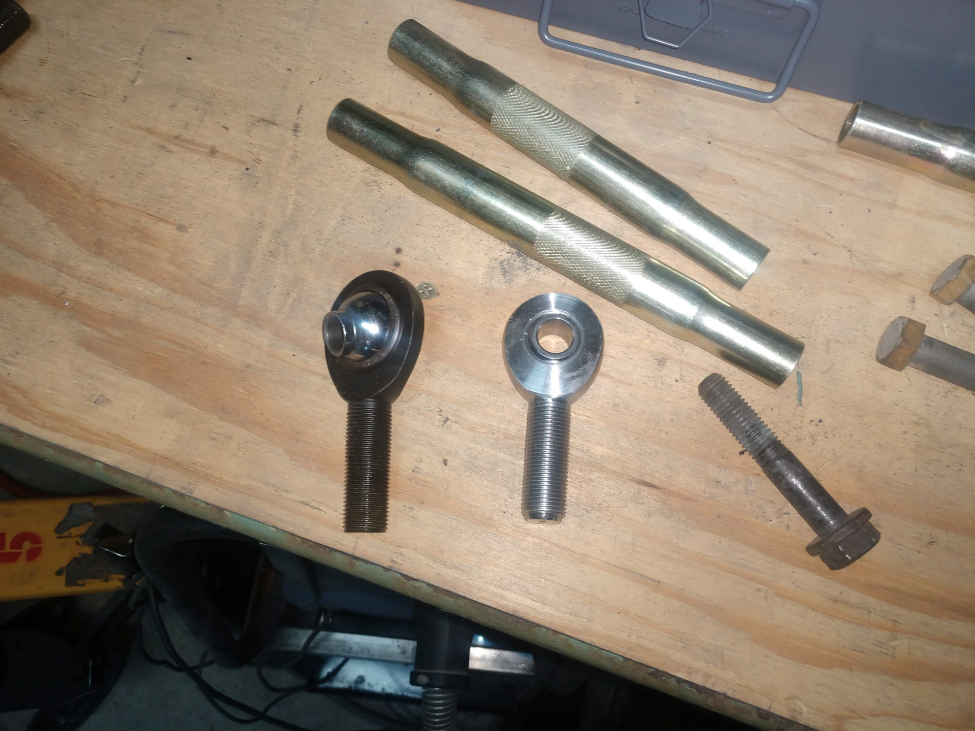
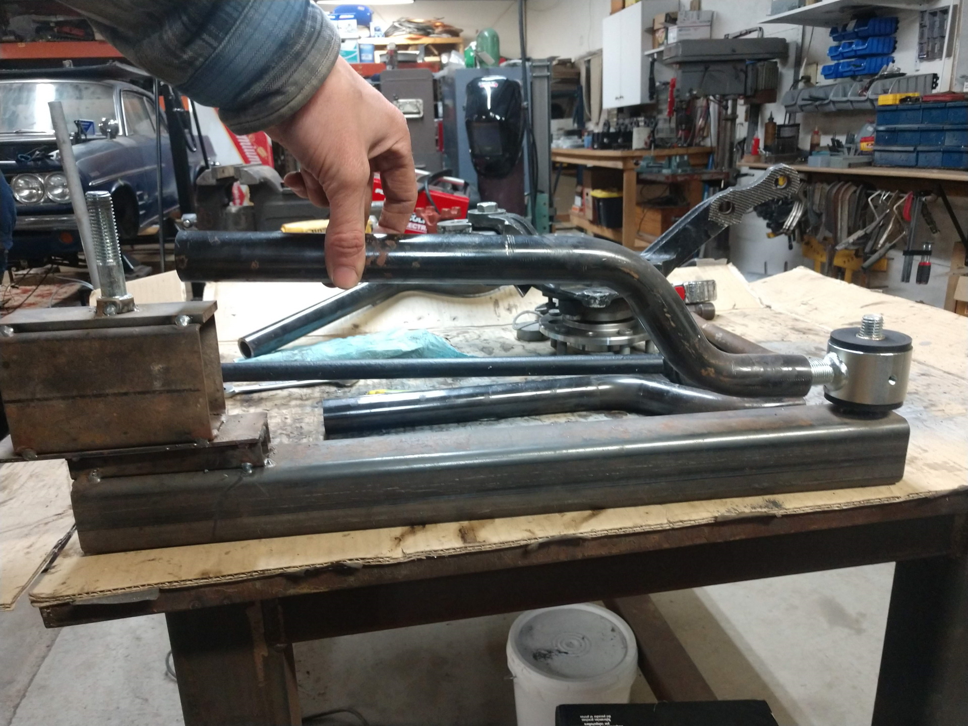
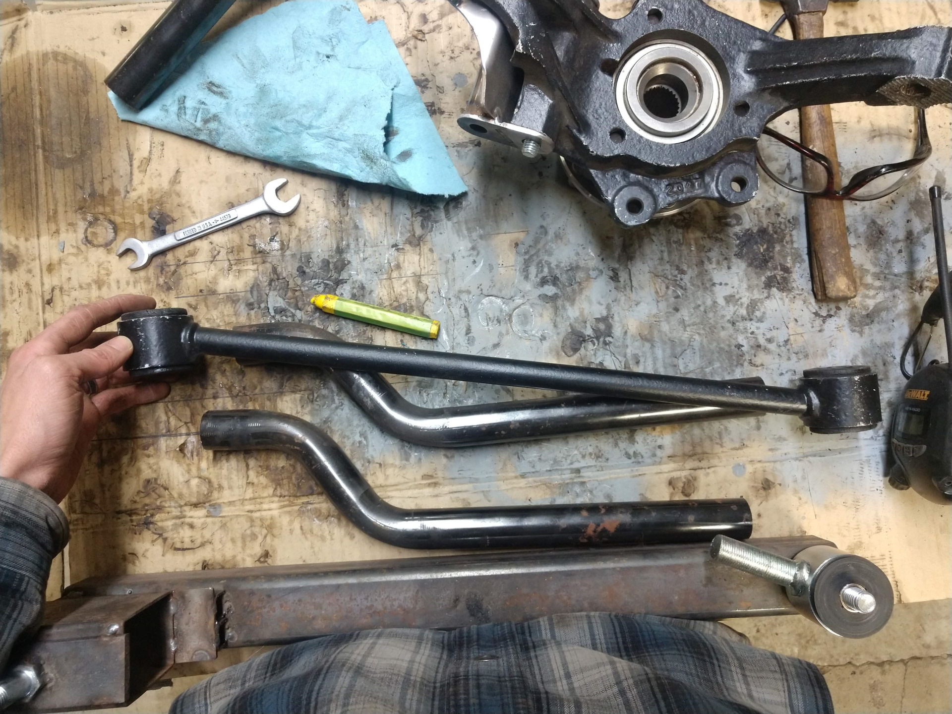
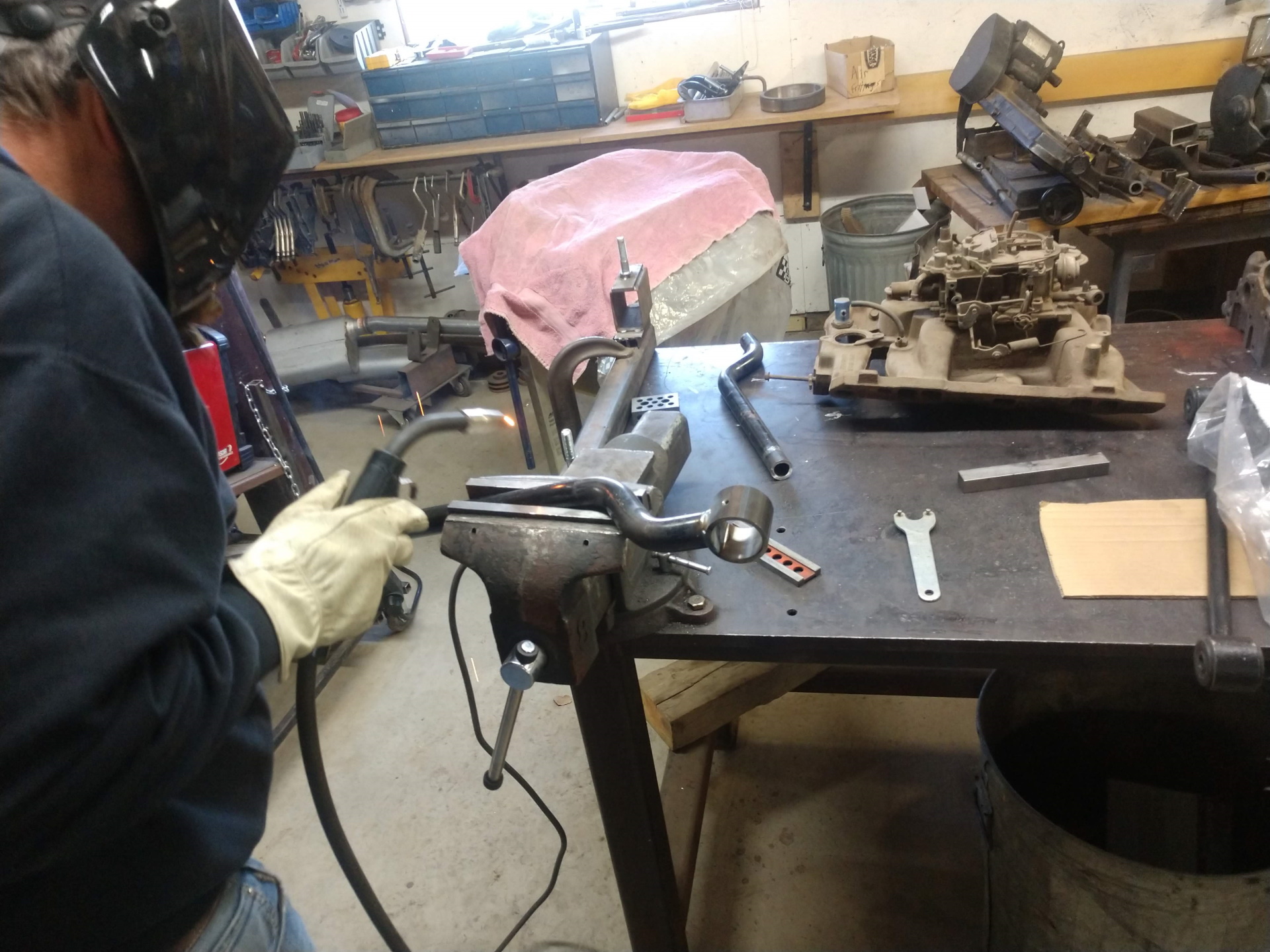
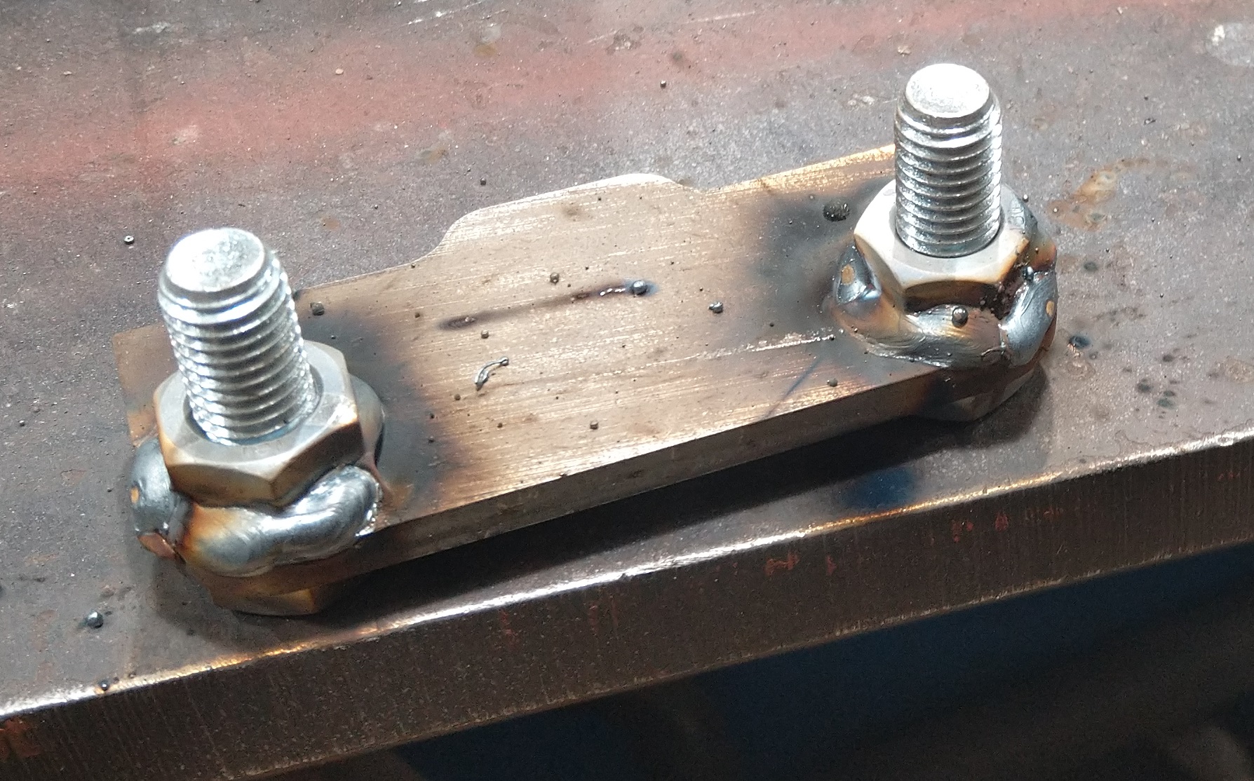
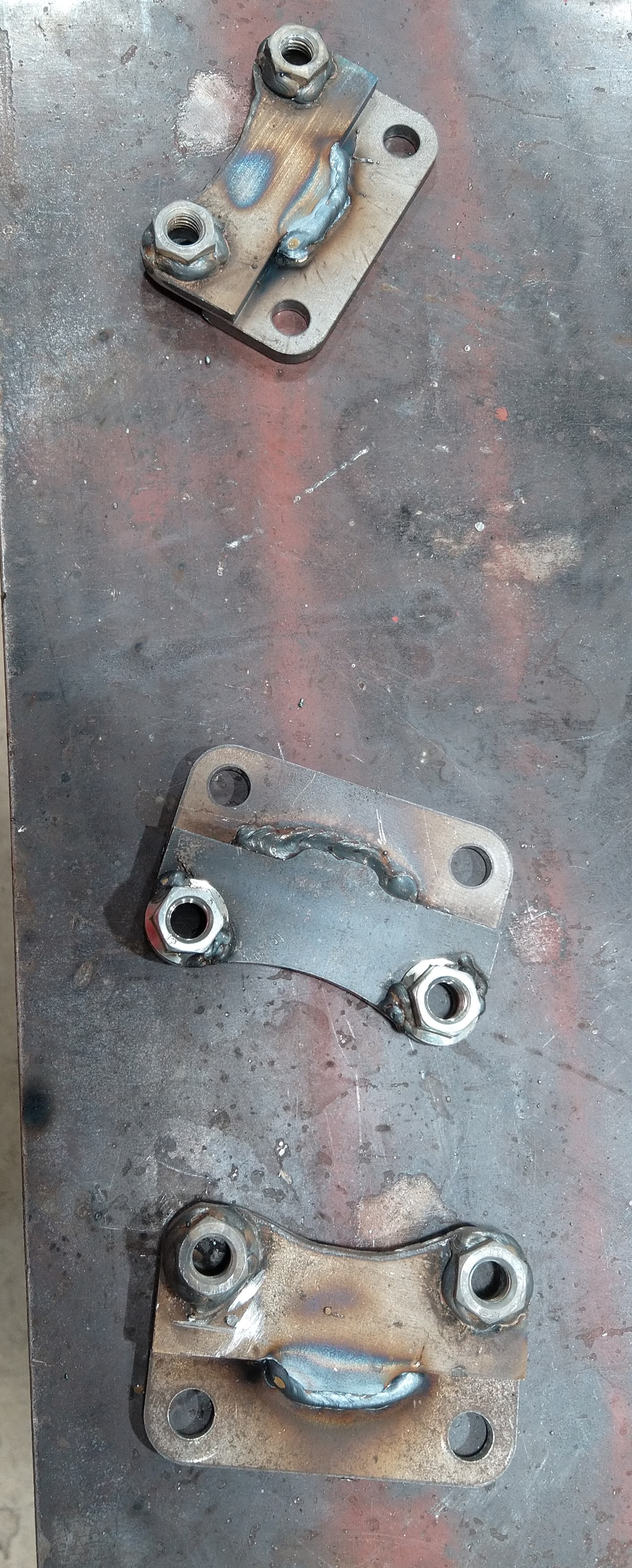
We see a lot of people use the dog bone bracket from the GP and mill off some material to mount a windstar tensioner. We decided to make our own dog bone mount and as usual made an extra one. I took a picture of all the pieces and the second picture is it partially welded. We don't have the brace welded in yet or the circle part for the tensioner. It worked out great as the spacing needed for the tensioner mounting surface is 1" from the cylinder head. We had one 1/4" spacer piece to bring the main chunk of metal away from the cylinder head to clear the valve cover. The second piece (main and largest) is 1/4" thick and then two circle pieces (1/4" each) for the tensioner makes it a total 1". The actual part that the dog bone will bolt to we will weld in last. This way we get some play with where to weld it on the main bracket.
The two thin pieces of metal are not used in this mount. I just happened to set them on the table.
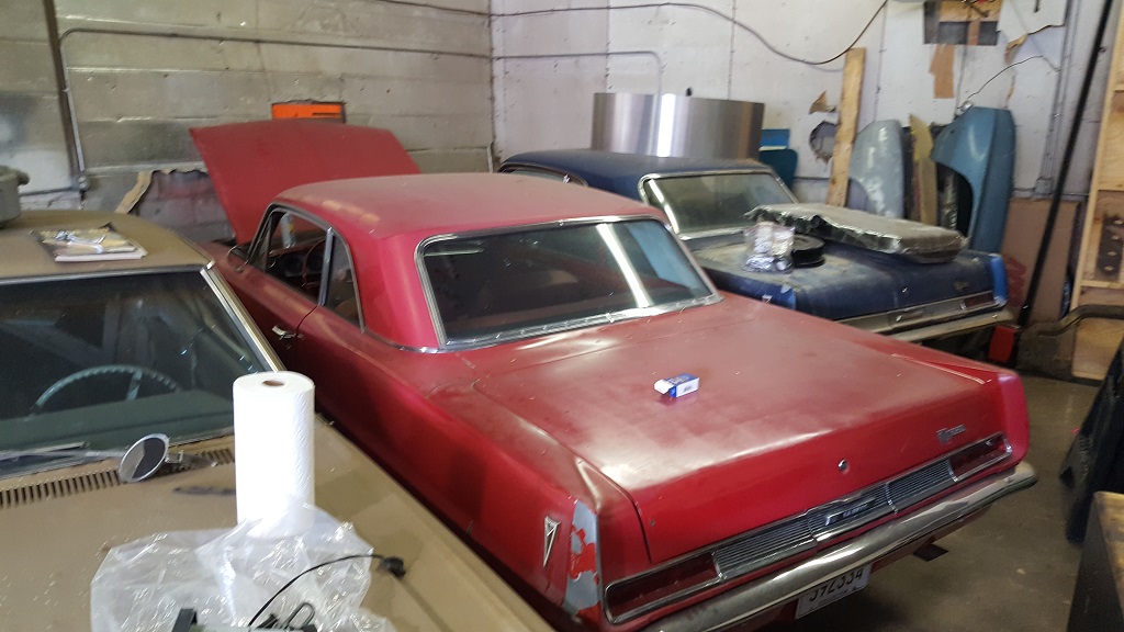
We went to look at a few cars for my dad. Any guesses what is in this picture?
If I forgot anything I will correct it later. Hope to get some progress soon.
Jncomutt Sorry for the year delay. I have had many things keep me from this project. I used the FY1 (longer) shaft. I used the spacer for mainly to keep the thickness of the flywheel. I don't have much more info on the hubs. I used S10 hubs and the part number from Fiero Guru. I had a shop do most of the machining as i did not have time.
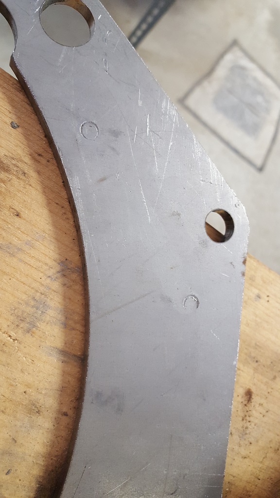
I am hoping to get some progress on the car after a long leave of absence. I still need to figure out the HTOB spacer. IIRC it was 1/4" but that was a long time ago. I will measure again before i go any further. I Found the the engine to trans spacer i made had interference with some bolts.
So i drilled them out.
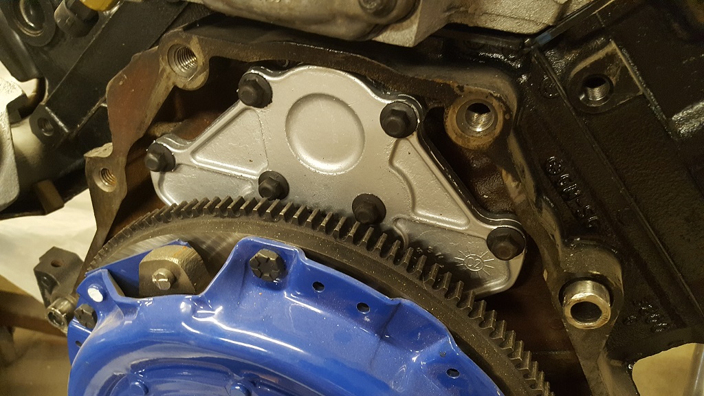
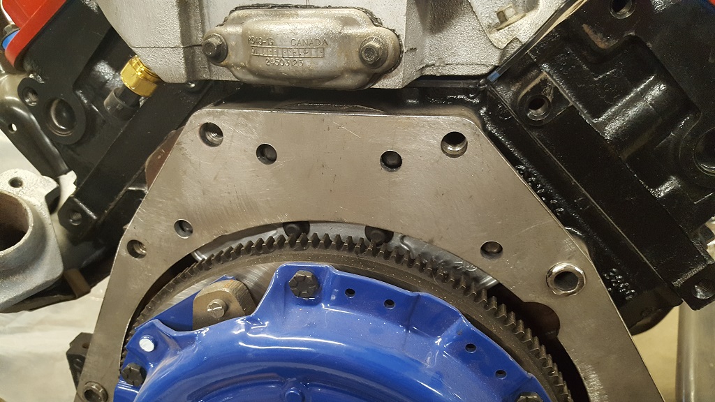
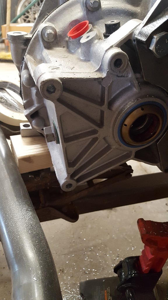
Then I started on the F23 mounts. This is a work in progress. I am waiting for a few more parts to finish it up. But I figured I would get started. I drilled and tapped the three spots here for bolts.
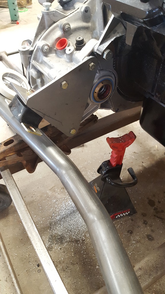
and here is part of the mount completed.
I hope to get some more done this week.
I like to share other fun stuff that is going on around the shop.
Here is my new back up car. 94 Corolla
two compressors i picked up for dirt cheap. they weigh 1250/950 lbs.
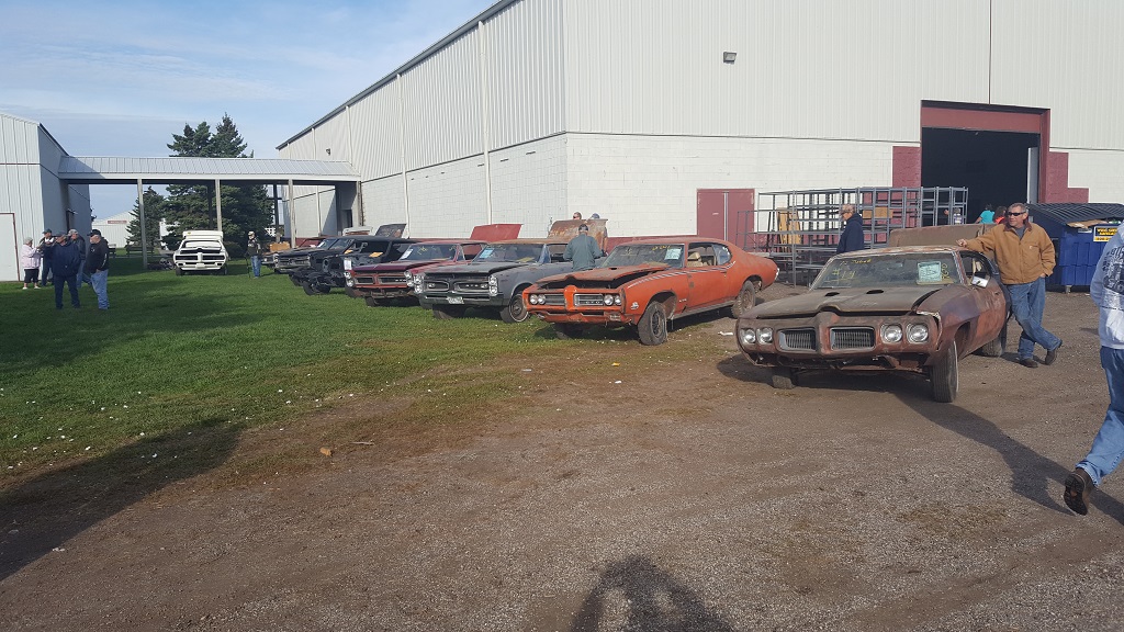
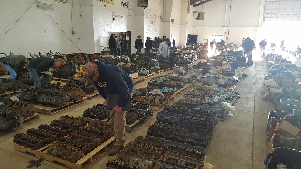
Minnesota Muscle liquidation (way bigger than the pics show)
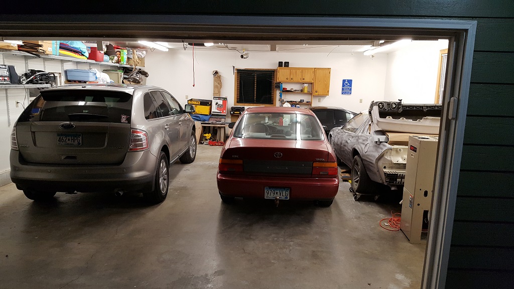
My 2 car garage that the wife said she needs a spot. I made it into a 4 car!
one of the many things that took priority. Getting my trans fixed in my 88 GT stock.
and check this out. 04 GTO....with......9,000 miles.....
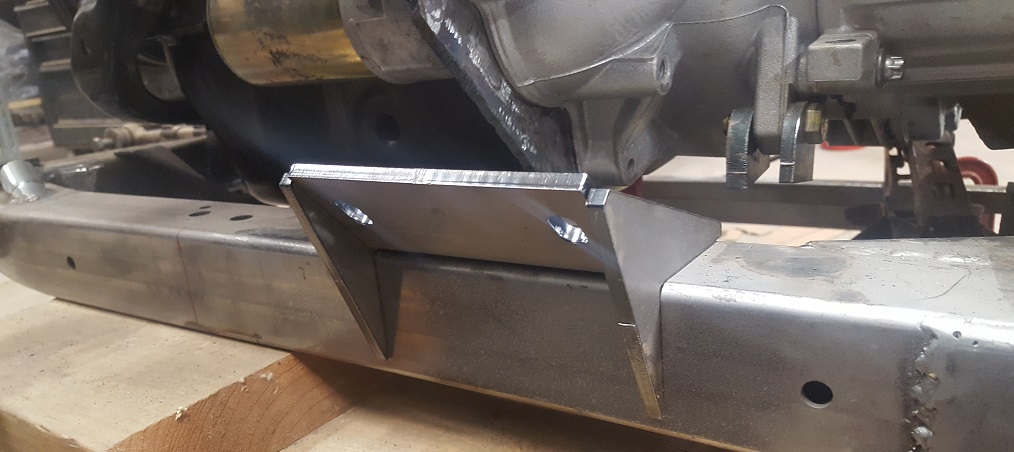
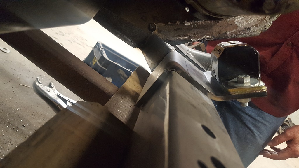
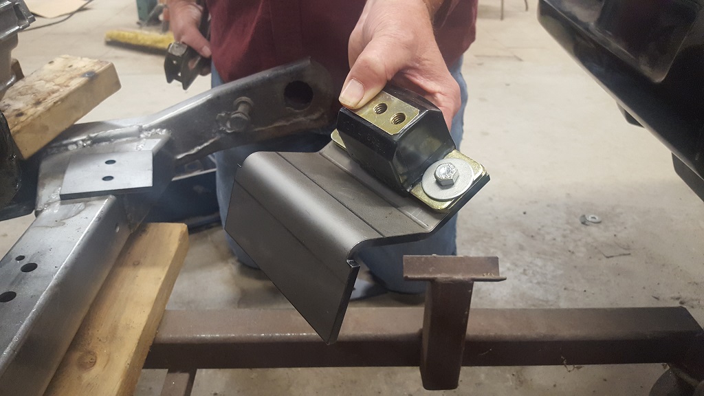
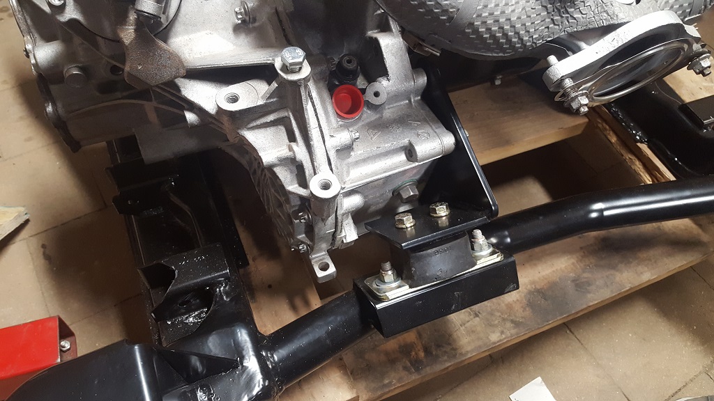
Here you can see the trans mount that i was thinking of doing on the right of the new mount. It is only on a small tab. I thought it was not strong enough.
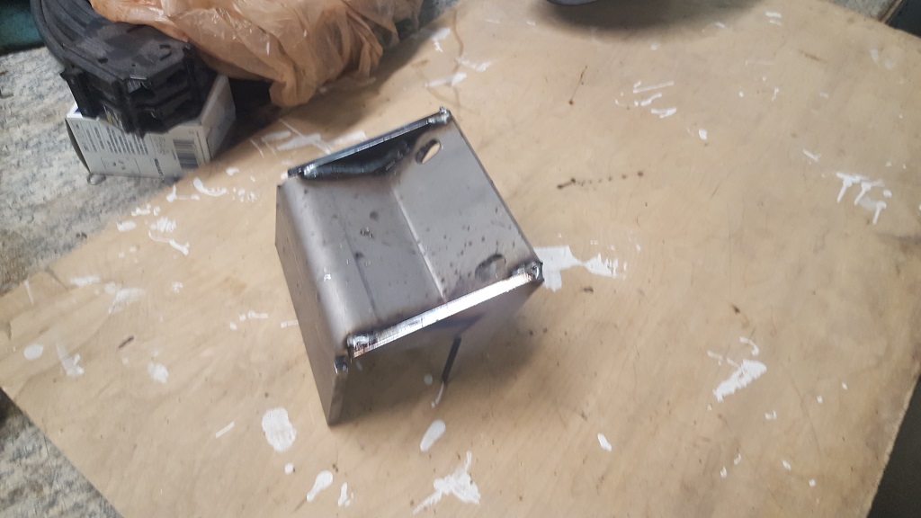
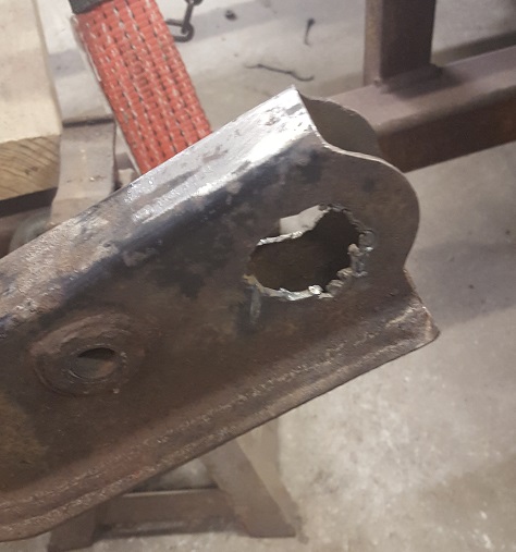
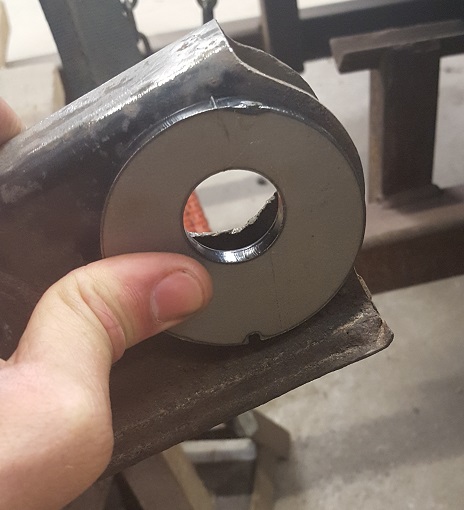
The front cradle mount to the frame was rusted and destroyed in removal. I decided to make a new design. The center hole is offset so i can lower (or raise) the car 1/2" I do need to account for the clearance with the deck lid.
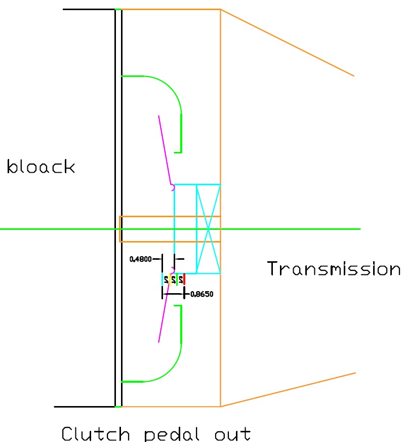
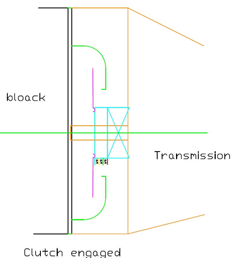
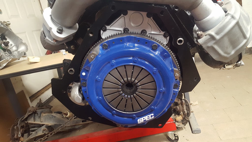
I used this process from Fiero Guru "First measurement: Distance from the bellhousing face to the tips of the pressure plate fingers. With the clutch/pressure plate bolted/torque to the flywheel, place a straight edge across the center of the pressure plate and measure the distance from the edge of the straight edge to the bellhousing face. If the fingers are recessed below the surface of the pressure place, measure that distance and subtract it from the previous measurement.
Second Measurement: Distance from the bellhousing face to the fully extended end of the HTOB. Install the hard line (or plastic bleeder fitting) to the HTOB to disengage the check valve (this is a critical step and where many people mess up). Let the spring in the HTOB fully extend it while you place the straight edge across the center of the bellhousing. Measure the distance from the bellhousing face to the fully extended HTOB.
Third Measurement: Distance from the bellhousing face to the fully compressed HTOB. It helps if you clamp your straight edge in place, as you will need 1 hand to compress the bearing and the other hand to take the measurement. Measure the distance from the bellhousing face to the fully compressed HTOB.
The difference between the 3rd and 2nd measurement is the normal range of motion of the HTOB. The first measurement must be between the 2nd and 3rd and ideally it would be 2/3rds of the distance from the second one and 1/3rd the distance from the 3rd one. As the clutch wears, the fingers will go closer to the HTOB, so you need to keep 1/3 of the range of motion for clutch wear and 2/3's for clutch release.
For example (not real numbers, just keeping the math easy to follow): say your clutch fingers are at 2.0" and the extended HTOB is 1.5" and the compressed HTOB is 2.25. The range of motion is 2.25-1.5 = 3/4". There is 2.0-1.5 = .5" of available travel to release the clutch. 2.25-2.0 = .25" of available travel for clutch disk wear, and 2/3 of the available travel is for release and 1/3 of the available travel is for wear. Some may argue that you should have a 50/50 split to maximize the wear life of the clutch and that could work, but I think 66/33 is a safer place to avoid the chance of over extending the HTOB.
I walked through this process in my LS4/F40 swap, but it also had to take into consideration spline placement and engagement since the input shaft is about 1" into the bellhousing. Not an issue for the F23."
this is the numbers i got.
I see that not only do I not need a spacer, I am .025 from bottoming out. Which would take pressure off the clutch while I am driving.
I am going to increase my spacer thickness from 1/4" (.25) to 5/16" (.3125) that will give me .0625 more space. Total space should be .0875
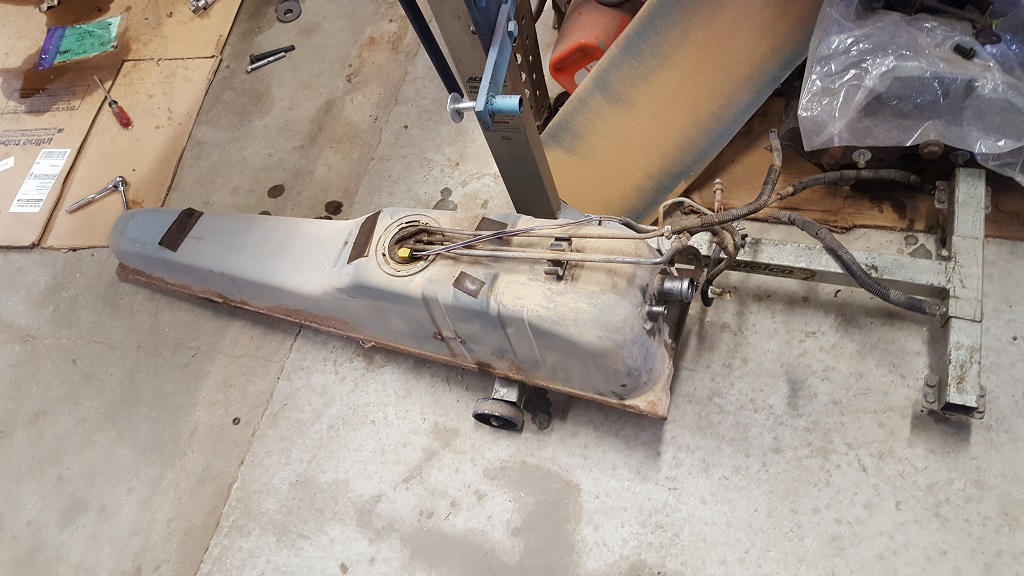
I pulled the gas tank. I wanted to get the new pump installed and run the stainless steel fuel lines.
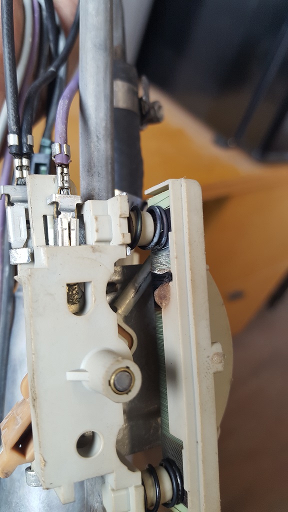
When I pulled the fuel pump out I noticed the resistor had a burnt part. I can only think this was very close to starting the fuel tank on fire.
If anyone has one I can buy let me know. I don't really want to spend the time converting it as some have done.
Originally posted by paulsobj: this is the numbers i got.
It would help if you label the measurements (or sketch out the parts with the dimension), it makes it easier for people to follow along.
Your use of the bellhousing spacer can confuse things, so it would be best to leave it bolted to the engine and take all measurements relative to the bellhousing face of the transmission.
This was a later post where I simplified things...
quote
Originally posted by fieroguru:
Most F23's should measure +/- .020" or so of the measurements I took (the bearing wobbles some, so there will be some variation in the measurement). The dimensions below were from a brand new F23 HTOB with the bleeder assy installed and open, so there was no air or trapped fluid to alter the measurements.
2.776" Retracted 1.899" Extended
With these measurements, the HTOB has a range of travel of about 0.877". If you go with the assumption that room for extension (releasing the clutch) should be 2/3rd (0.585")to 3/4ths (0.658") of the available travel,
Then you want the clutch fingers of the pressure plate to be between (1.899 + .585 =) 2.484" and (1.899 + .658" =) 2.557"
So measure your clutch fingers and see what the dimension is. If it falls between 2.484" to 2.557 then you don't need a HTOB spacer. If not, then a spacer is needed. For example if your pressure plate fingers are 2.200" from the bellhousing surface, then you will need a spacer 0.284 to 0.357" thick.
FieroGuru, Thanks for the input. I am going to repost HTOB when I get the new spacer made. I am making two (1/2 and 3/8) just in case one works better. I will try to illustrate it better with more pictures and drawings.
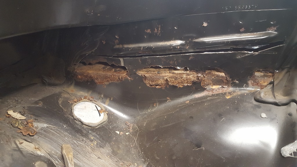
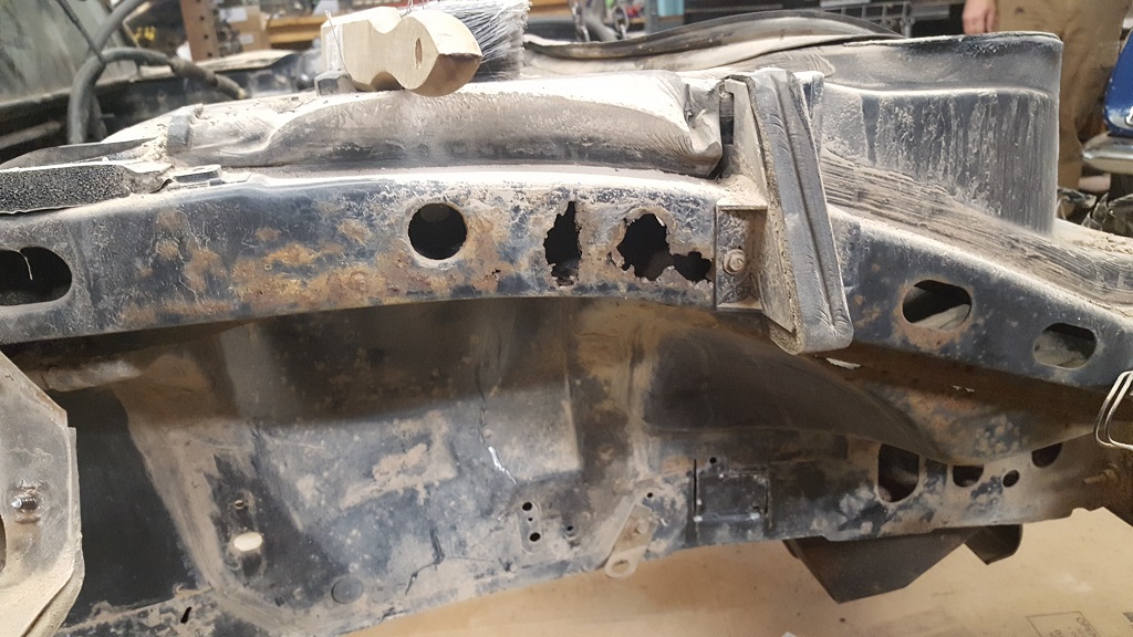
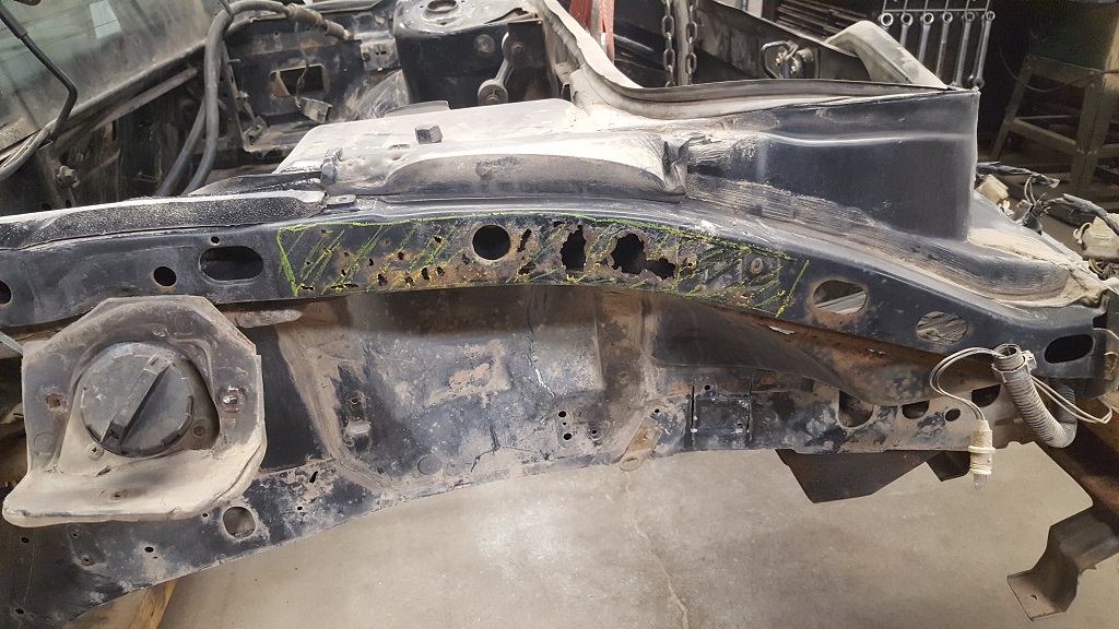
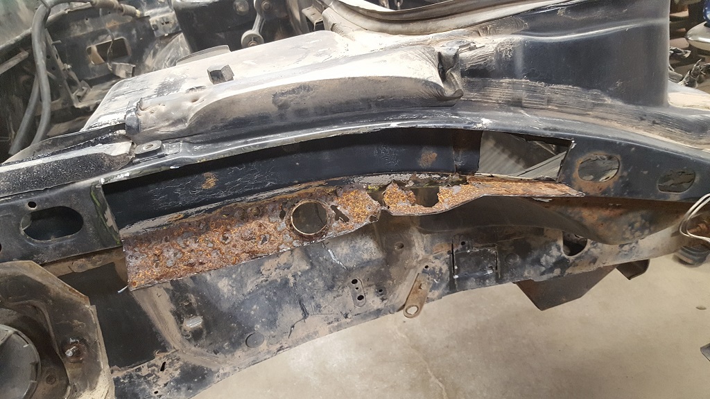
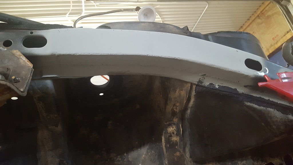
Tonight I worked on getting the engine bay cleaned up. This is the worst of the rust that i can find.
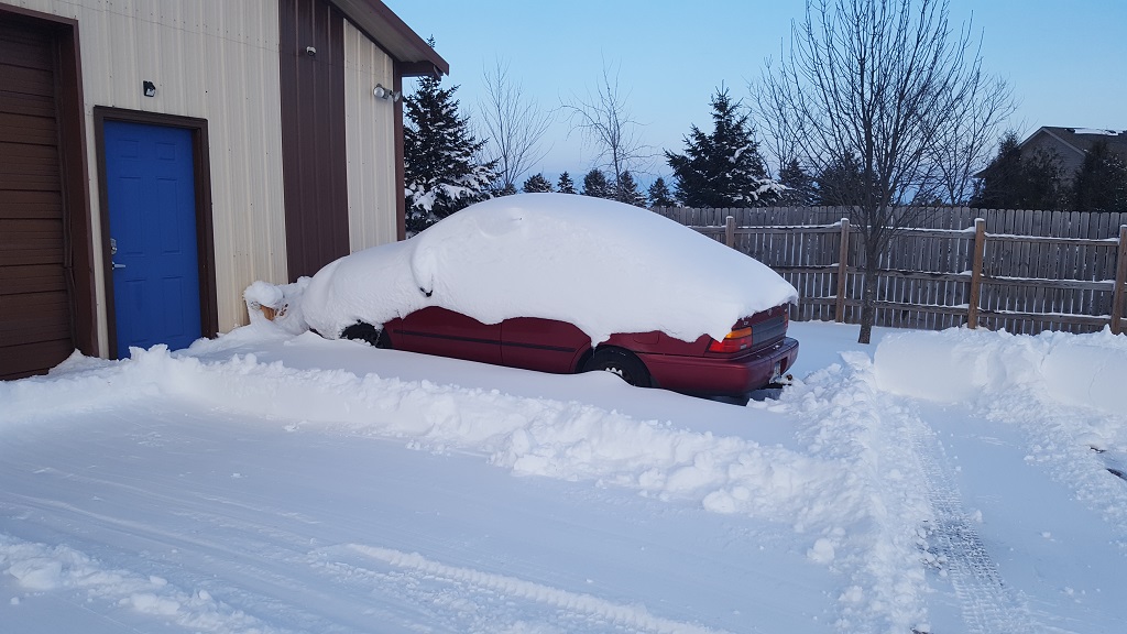
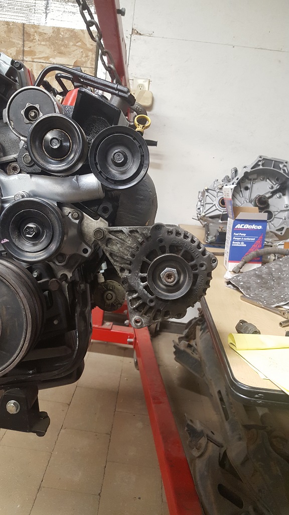
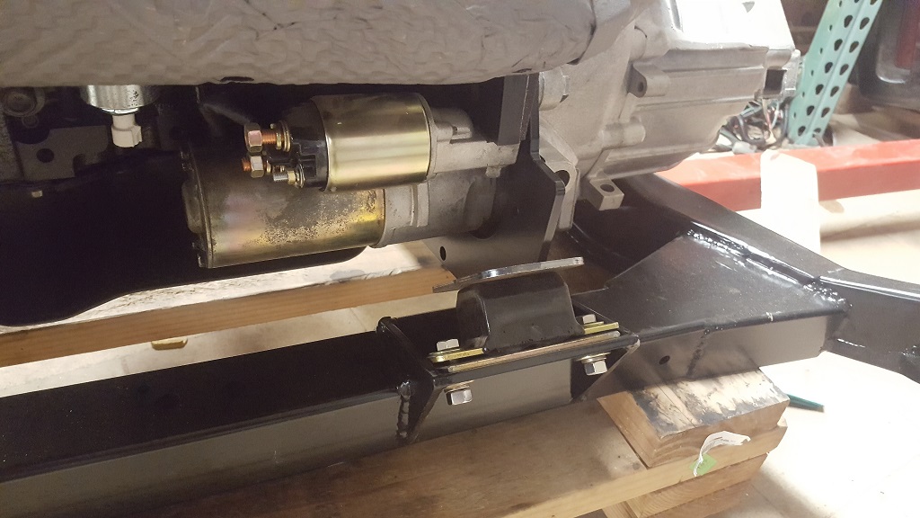
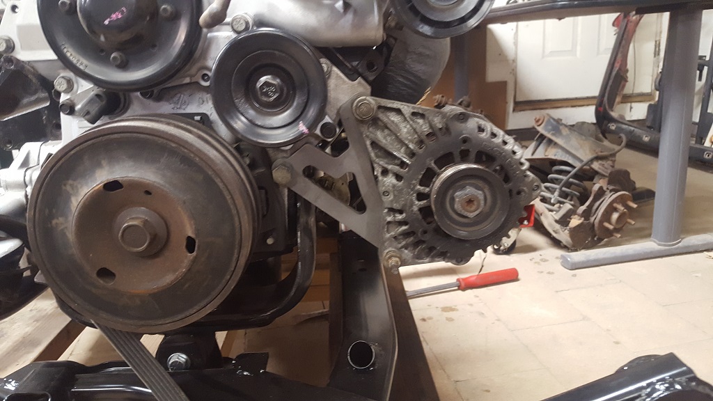
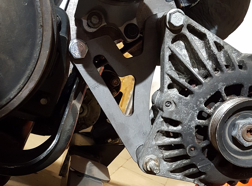
I went out to the 98 GTP I traded and pulled the alternator. If you look back a few posts you can see my backup car covered in snow. So getting the alternator out of the GTP was not easy or fun when its been sitting outside all winter. I almost froze my fingers off. I am mounting it like shown.
The trans spacer should be getting cut tonight. So stay tuned for that.
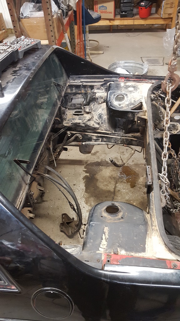
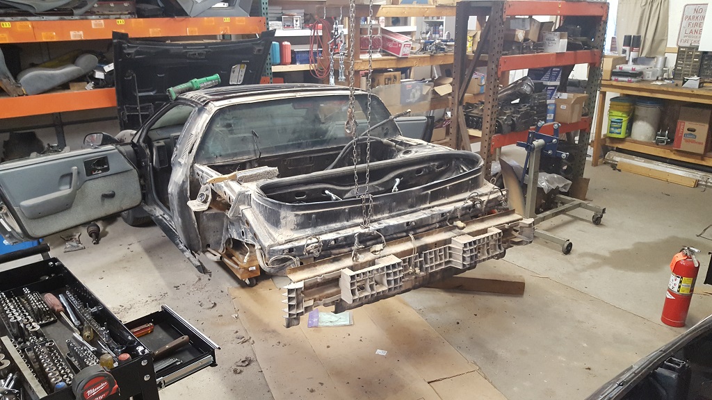
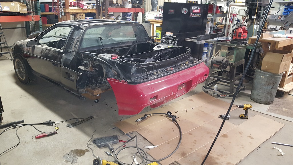
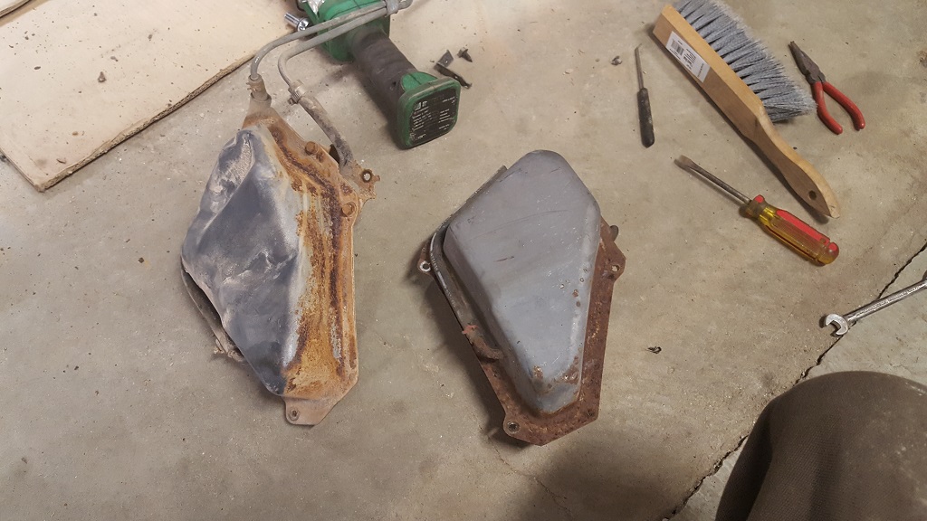
I needed to get the fuel expansion tank replaced as the one on the car was smashed up a bit. I could get it out but when I went to put the replacement in it I couldn't reach the bolts. So I have to take off the rear clip. I decided that I am going to move ahead with the GT clip swap. I should have almost everything for this. I need the rear bumper support still. If anyone has one for sale let me know.
I also wanted to get a better look at some rust that needed repair.
I didn't get a picture of the passenger side but this car was hit at one point. The expansion tank was crushed a bit, and under the quarter panel there was dents from body repair. I didn't see any gap issues so lets hope everything fits back when I start assembling. So the rear clip must be from another car or NOS depending when the repair was done.
Well I didn't get pictures of everything that I worked on tonight. I might save it for the next post.
I got the rear GT bumper on. I had to replace the bumper support and the wiring harness. I should have replaced the lower bumper support but I don't think it is critical. Looks fine as is.
This is the whole reason I took off the rear clip.
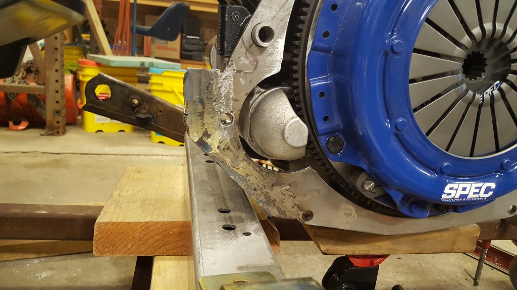
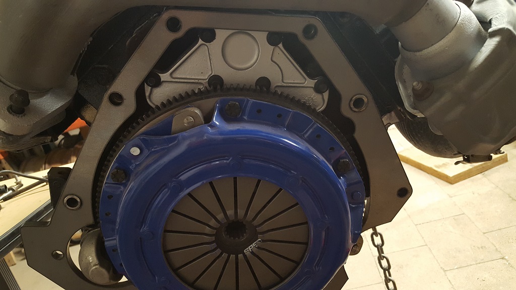
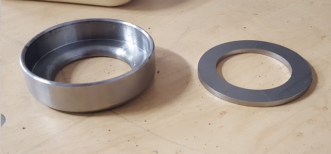
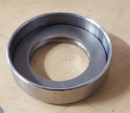
I got the thicker 3/8" spacer done. You can see i took some material out for weight and no real reason to have it.
I found the 1/4" cleared the flywheel but this thicker one interfered with it. I had to machine off some material to clear it. I didn't want to cut all the way through to keep some strength as a full circle. I have an extra one that I machined the wrong side. So if you want it you will need to cut it so its not a full circle. This is a picture of the mistake.
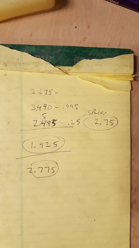
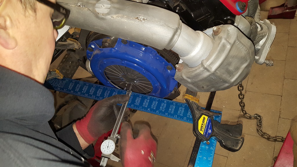
I measured the HTOB again. This time I left the spacer on and had to subtract the measurement I read from the thickness of the blocks you see in the picture.
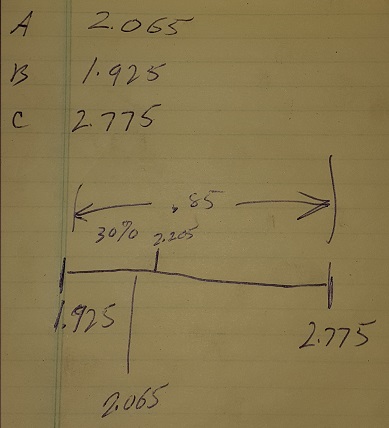
Looks like I have 2.065 from the face of the spacer to the fingers (measurement in the picture above) The HTOB face to the bellhousing/spacer face is 1.925 extended and 2.775 retracted.
Before I was almost bottomed out for the HTOB and now I have about .14 clearance.
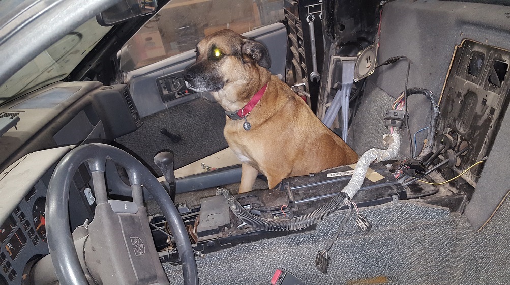
My Dog was letting me know he wants me to get this thing done.
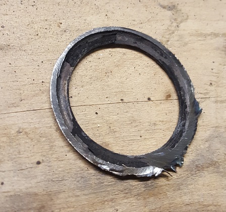
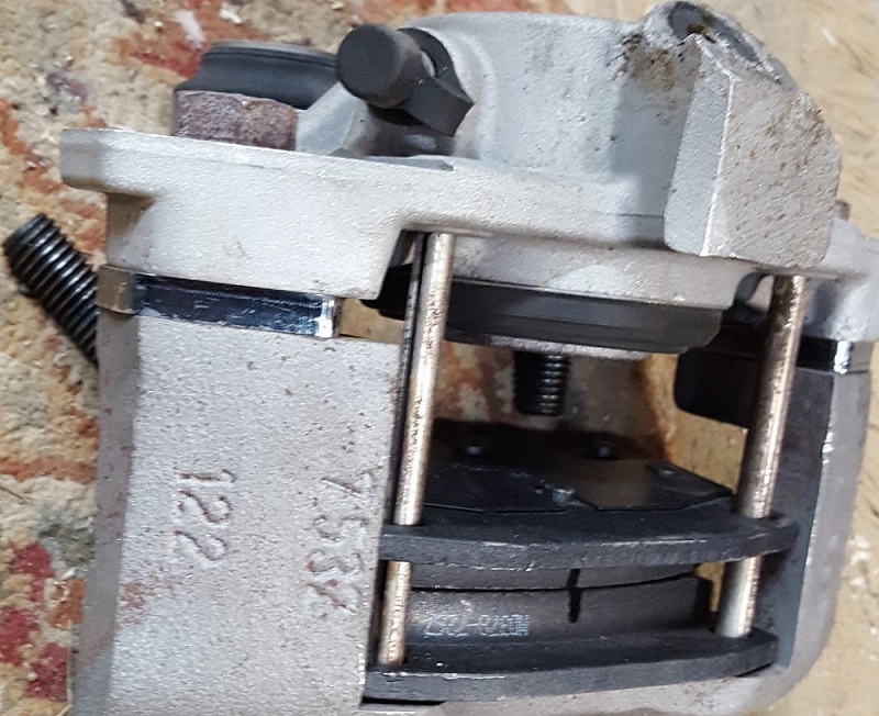
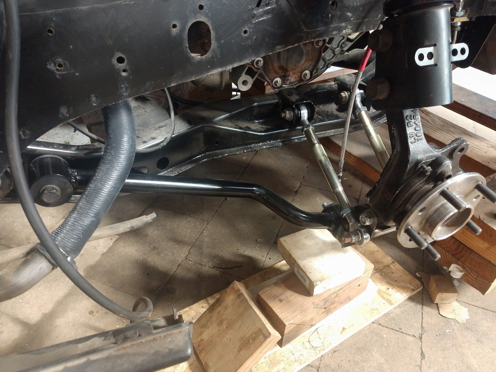
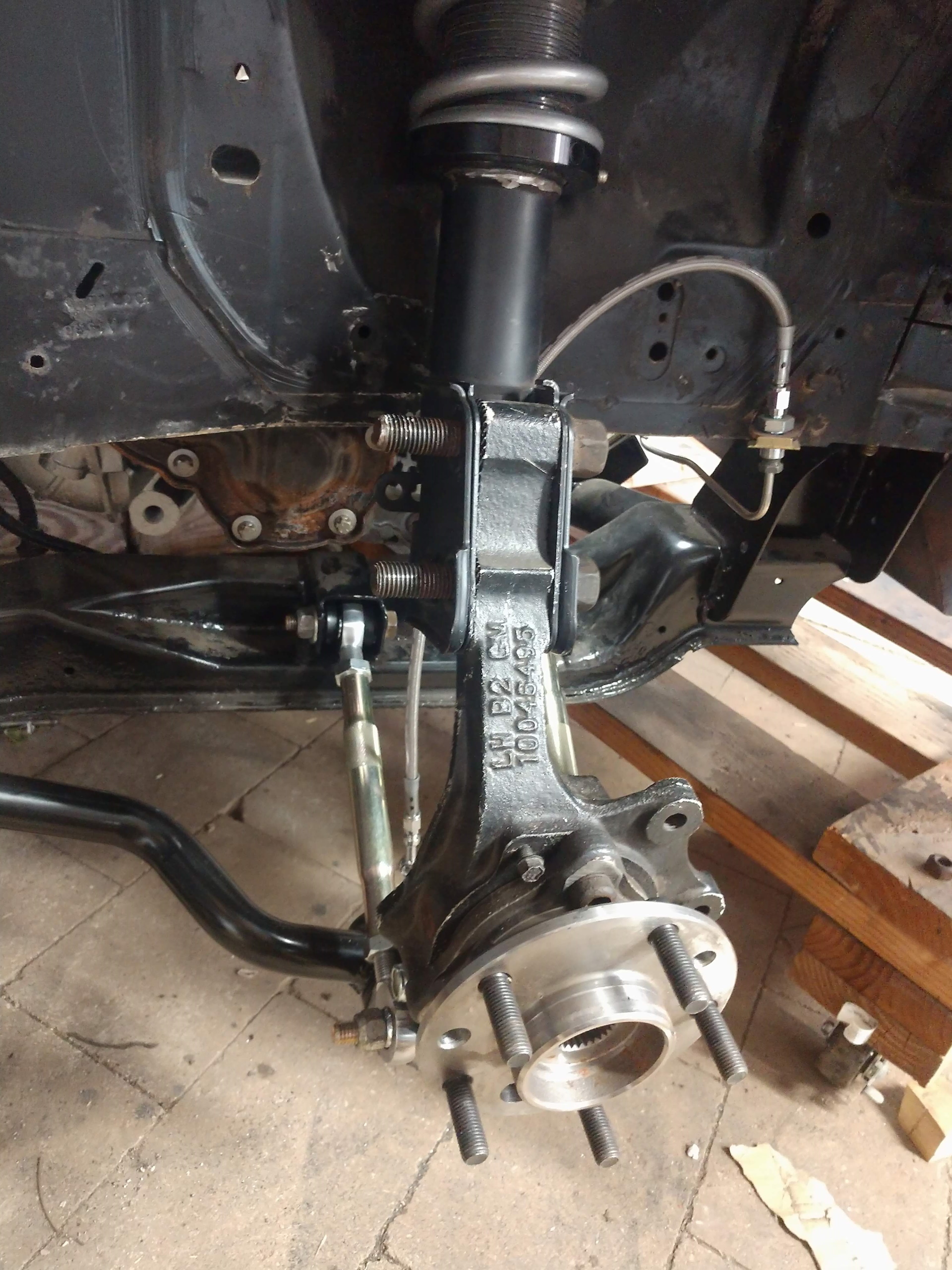
I also needed to get some brackets made asap. So I worked on lateral link relocation and brake caliper spacers.
I measured the HTOB again. This time I left the spacer on and had to subtract the measurement I read from the thickness of the blocks you see in the picture.
Looks like I have 2.065 from the face of the spacer to the fingers (measurement in the picture above) The HTOB face to the bellhousing/spacer face is 1.925 extended and 2.775 retracted.
Before I was almost bottomed out for the HTOB and now I have about .14 clearance.
Working with these numbers can be a little counter intuitive, as you press the clutch pedal to release the clutch, the distance from the bellhousing face gets smaller. with the 30/70 split, you want the 70% on the release side, and in your diagram you have the 30% on the release... With the current setup your HTOB will over extend.
Pressure plate opened with pedal pressure and HTOB Fully Extended: 1.925 (1.899" from my transmission - within 0.026") Pressure plate closed (clamping the disk): 2.065 HTOB fully retraced toward the transmission gear case: 2.775 (2.776" from my transmission - within 0.001")
Range of Motion 0.85 (0.877" from my transmission - within 0.027") 30% distance: 0.255"
To give yourself 70% of the Range of Motion for the HTOB to extend and the pressure plate to release its grip on the clutch disk, subtract the 30% from the 2.775 = 2.52" (2.484" to 2.557" was the safe range of 33% to 25% for wear, 66% to 75% for extension for my transmission)
This is where the HTOB needs to be when it makes contact with the pressure plate fingers with the pressure plate clamped to the clutch disk. Your 2.065 is 0.455" from 2.52", so you need a 0.455" spacer.
[This message has been edited by fieroguru (edited 03-23-2018).]
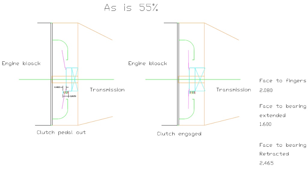
I see that I had a few things backwards. I also think I didn't measure something right after looking at it more. So I decided to get it drawn up in CAD and then be able to really check myself. I remember that i was going to us a 1/4" trans spacer based on the face that most people machine down the flywheel 1/4" to get clearance with the pressure plate and the trans case. Those same people seemed to unusually needed a 1/4" HTOB spacer. Now, after throwing out all old measurements and starting fresh. I think I need 1/4" trans spacer, 1/4" HTOB spacer. Don't mind the misspelling....
Here is with an additional .100 washer added to the Spec HTOB .25" spacer.
I hope this is the final cut.
With the HTOB .25"spacer.
Some rust repair.
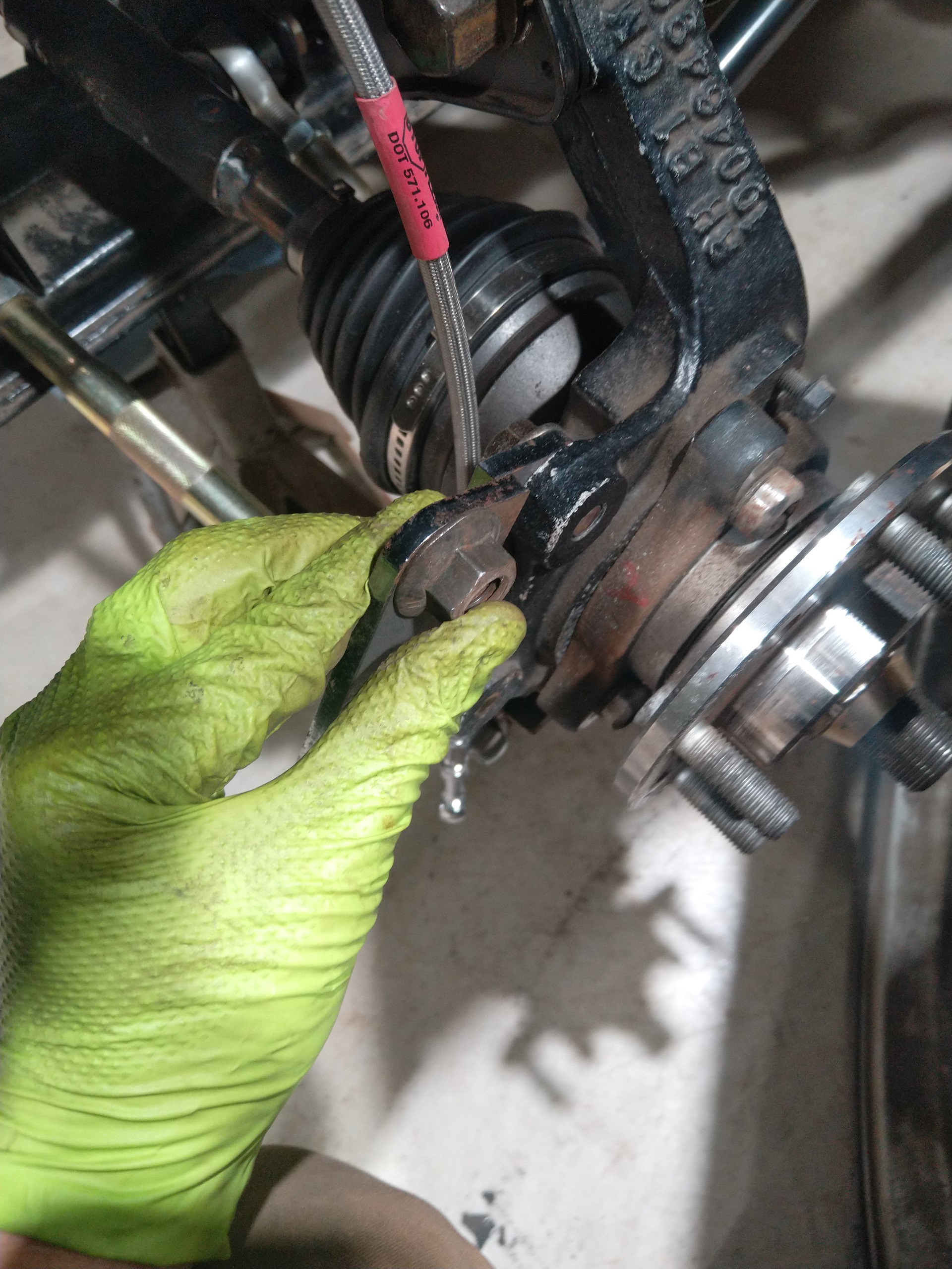
I installed all new SS brake and clutch lines from TFS along with poly bushings. I found that I had a full set of ball joints and tie rods that i forgot about. Gas tank is almost back in. I have other things I would like to update on but I feel its incomplete. I also broke the rear brake line junction block and found how hard it is to get ...even used...
I have been working on my '75 T/A while I was waiting for sand blasting and powder coating. Blasting was done at my dads old business Blast Master in Shakopee, MN for $200. I just picked up the parts today from Extreme Powder coating in Blooming Prairie, MN for $425.
Here is the spacer that I made to get the correct spacing.
I got the thicker 3/8" spacer done. You can see i took some material out for weight and no real reason to have it.
I found the 1/4" cleared the flywheel but this thicker one interfered with it. I had to machine off some material to clear it. I didn't want to cut all the way through to keep some strength as a full circle. I have an extra one that I machined the wrong side. So if you want it you will need to cut it so its not a full circle. This is a picture of the mistake.
.
I'm interested in your bad plate, It will make a good starting point for what I need for my Nstar/f23 swap, 3/8" will give just enough room to clear the flywheel/clutch combo I got from CHRF. Nice work on your build.
motoracer838 email me and I can get that to you. Thanks for reading my build.
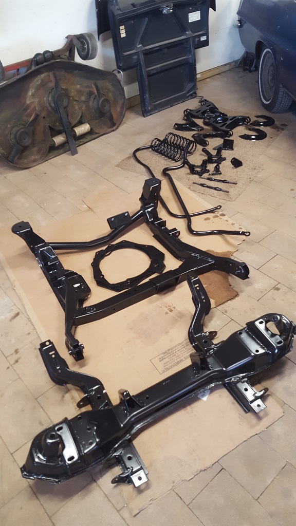
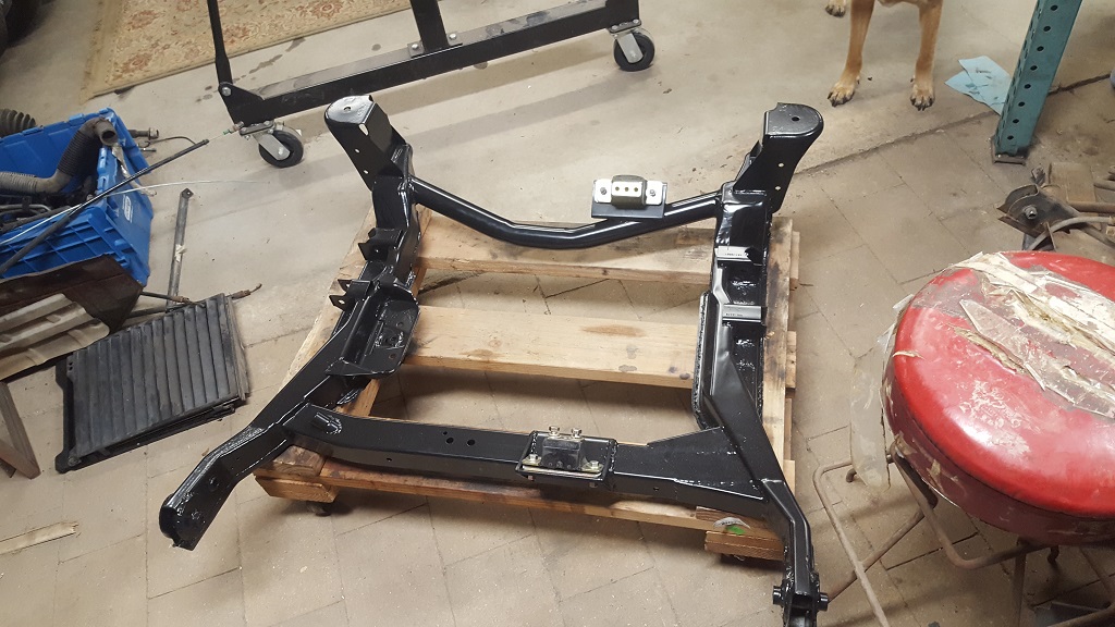
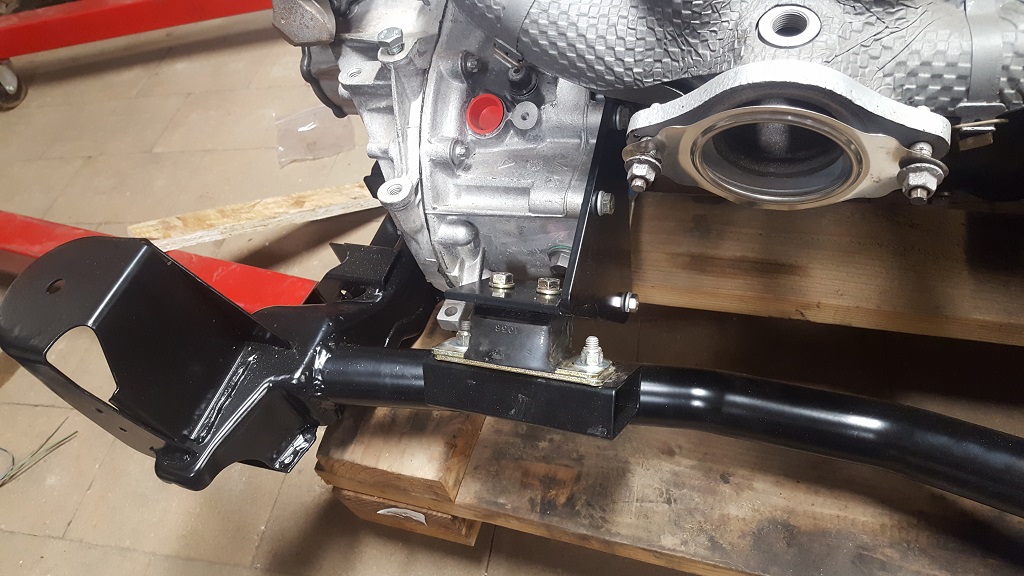
I am glad to start assembling and not taking apart the frame and suspension. Here are some pics of my engine mounts.
Here is the final trans spacer (I hope haha)
The cradle
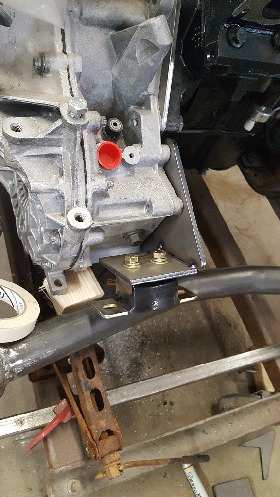
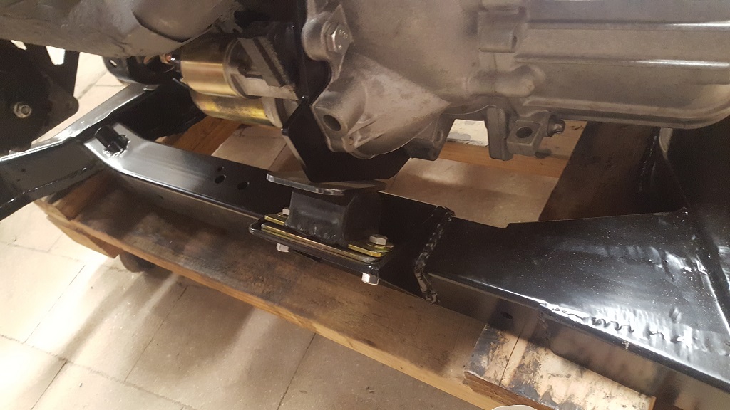
This is the front trans mount. I have not welded it completely but you get the idea. It is welded to the trans spacer I made. We added a small tab to use as a mount point.
Here is the rear trans mount. We drilled and tapped the three spots on the F23.
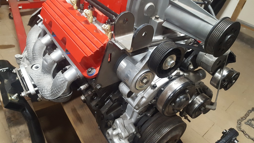
Alternator mount
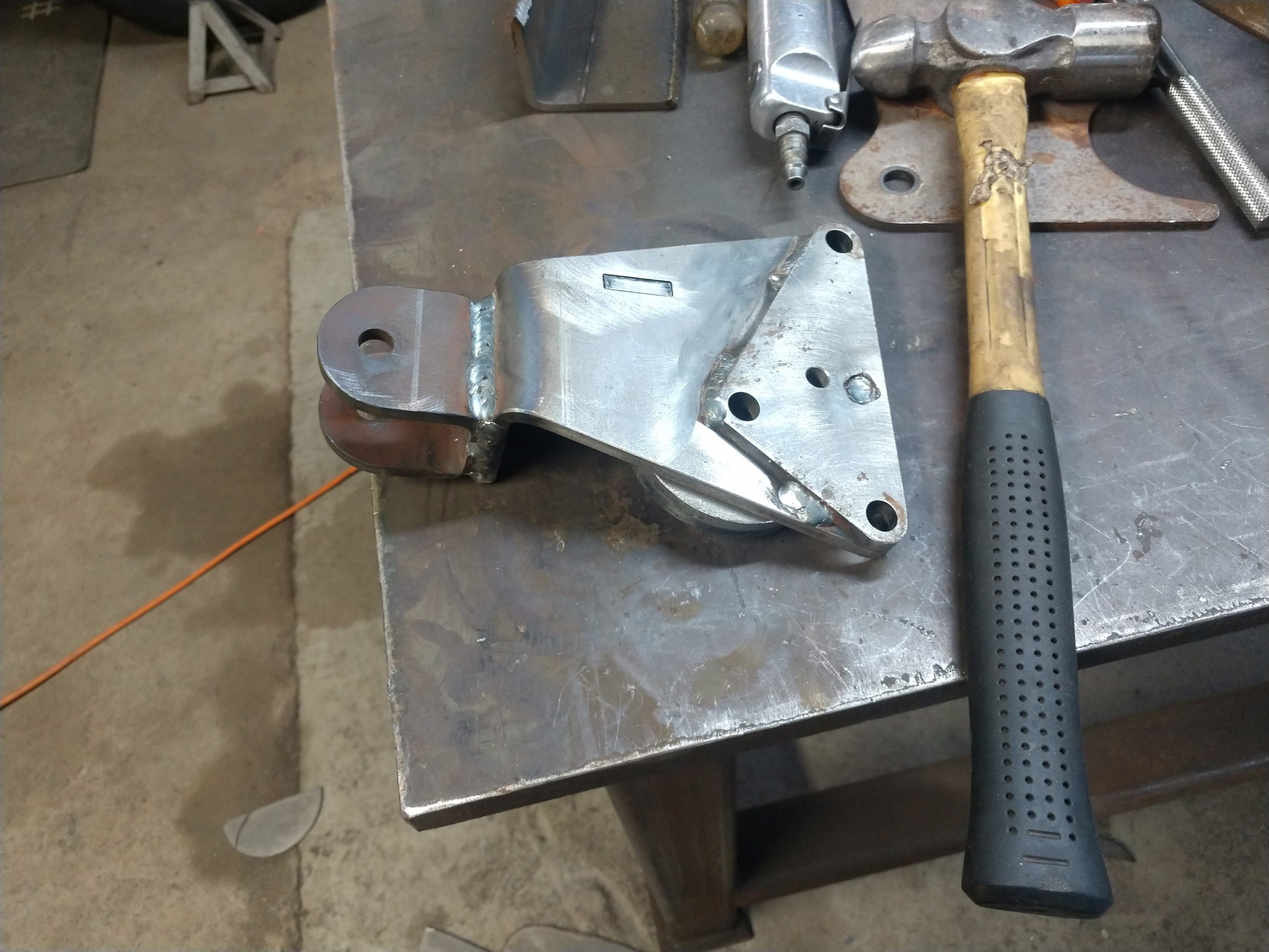
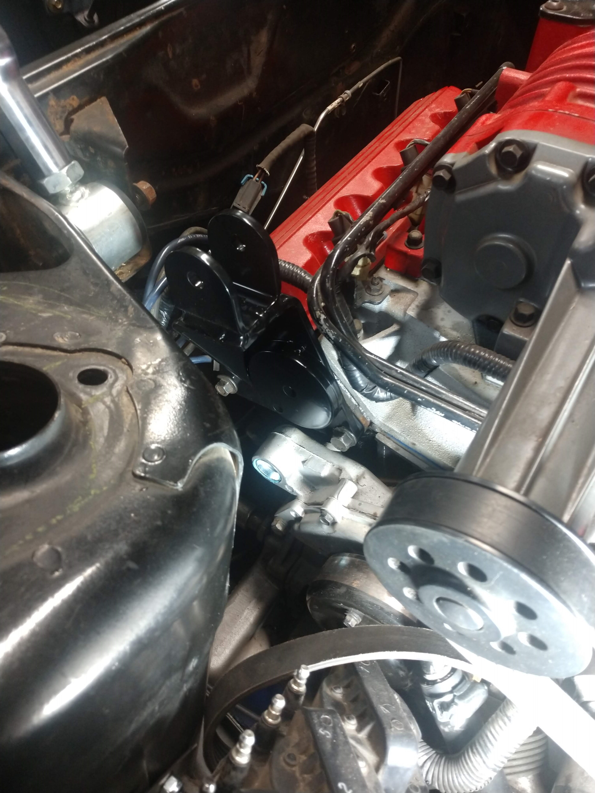
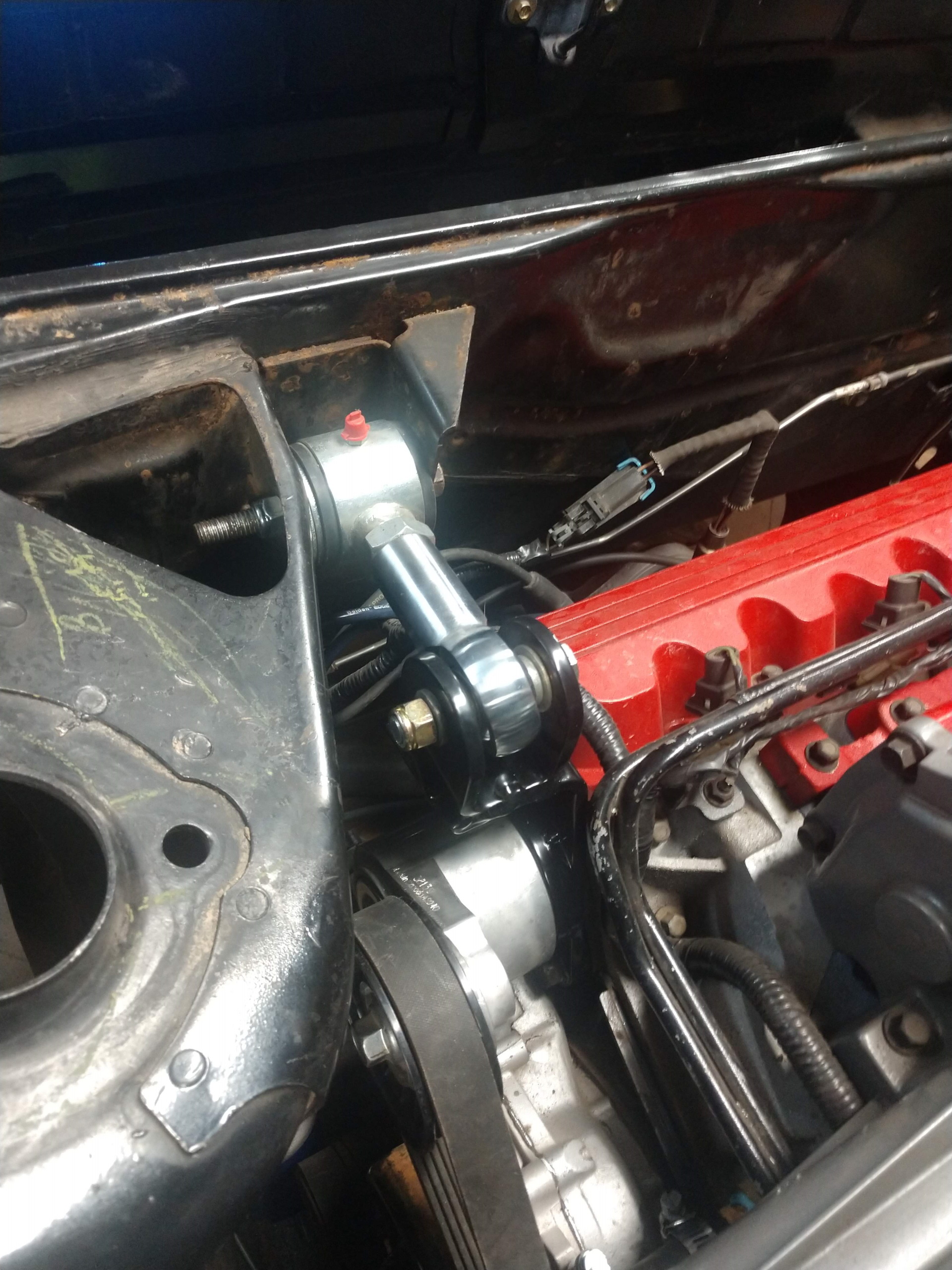
Dog bone mount
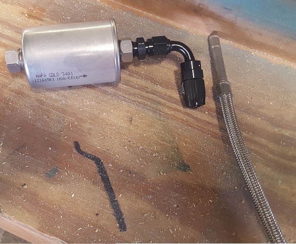
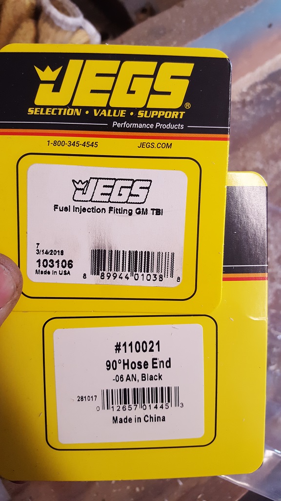
Sorta random but If I don't post now I will forget. This is the AN adapter for the stock fuel filter to stainless steel lines I am using.
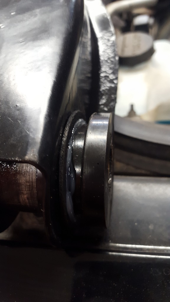
I got most of the drivers side front suspension done tonight. I had issues with the bushings. I didn't know that I needed to keep the OD metal from the original bushings for the poly that I bought. So I had to buy a whole new set and push them in and heat up the lower rubber until it popped out and pressed out the upper rubber. I destroyed my vice doing so. It was a really old good vice that I will have to replace soon. After I got the bushing OD figured out i put the poly into the A arms and noticed it was not right.
You can see the gap.
But it was all the way in.
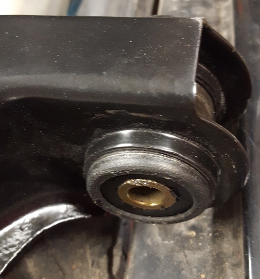
So I found the OEM bushings did not have the inner lip. So I cut it off.
Beautiful paint job on the engine/trans. It looks like you're painting it just the way i plan on painting it. The valve covers and the supercharger look super!
jon
------------------ I'm the original owner of a white ' 84 2M4 purchased Dec 10, 1983 from Pontiac. Always garaged, no rust, 4-wheel drifts are fun! 3800 SC swap to come!
I have not had time to get around to working on it in a month or so. My parents just moved and I have been helping them. I think next is drilling the bolt pattern for the front hubs. I bought RD blank rebuildable hubs. I always seem to get busy in the summer around here. I am going to the Pontiac Nationals Monday and Tuesday in The Dells. I think we are taking the Solstice and mainly going for the swap meet. I might take another vehicle as the Solstice doesn't have much room for parts if we buy any.
Another long period of no updates. I do have some finally! This summer was very busy and since my last post I have one more member of my family. I also bought a 15 Explorer Police car for the growing family. I picked up a new toy for the shop last week, a CAT skid steer. I had to install Rodneys input shaft bearing seal for the other Fiero. You mightt remember that I did it in March and the Seal was bad for the rubber piece came out. I wasn't taking chances and installed the kit in November.
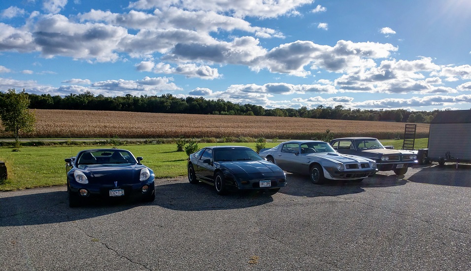
Here is a picture that my dad took this fall.
I would love to post pictures but after copying and shrinking it they are smaller then a postage stamp. what a joke. I guess I will have to get my old cell to take pictures. I might take less pictures and post less because of this size limit.
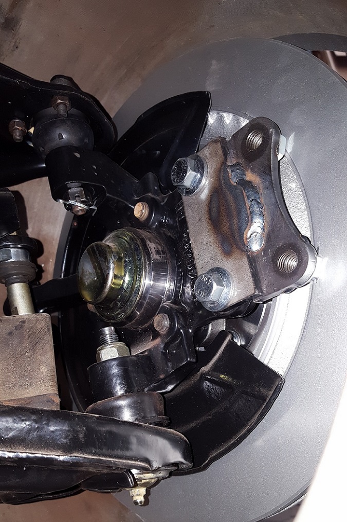
I got the front hubs drilled and the studs pushed in. I bought some tubing to make centric rings and made brackets to get the caliper moved out to make room for 13" rotors. I had to make some 1/4" spacers for the caliper to clear the thickness of the rotor. I ordered tire today, I got 245/40ZR17 SUMITOMO HTR Z III XL for the front and 285/30R18 for the rear. So the front should be done except for bleeding the brakes.
If anyone knows a good program to reduce the quality of pictures let me know. I do have lightroom and PS but I am not fluent in it.
[This message has been edited by paulsobj (edited 02-21-2019).]
I took a few pictures with my dads cell. I hope they are poor enough quality to be under the maximum.
Here is the alternator bracket i made.
Here is the caliper spacers.
We made the caliper bracket in two parts to get the offset. To get the correct spacing it would be hard to measure. So we bolted the two parts to the caliper and the spindle and set the caliper on the rotor. I used two small ~1/8 spacers to keep the caliper from resting on the rotor. Spun the caliper to the correct position and tac welded the two parts. Took it apart and welded the bracket up.
Here is the set up
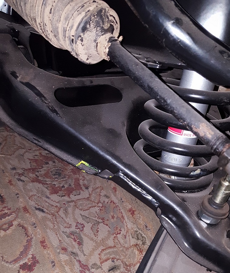
I found i need to notch out a small area on the lower A Arm.
I finally have a few updates to post about. I found that paint.NET will compress the quality of my pics so i can post. I will have to go back a bit.
I pulled the trans out of my other Fiero to get the input shaft bearing fix done. This car was out for almost two years because of that.
Here are my lateral link relocation brackets, I told my dad what the goal was and he designed them a little different than Fieroguru's.
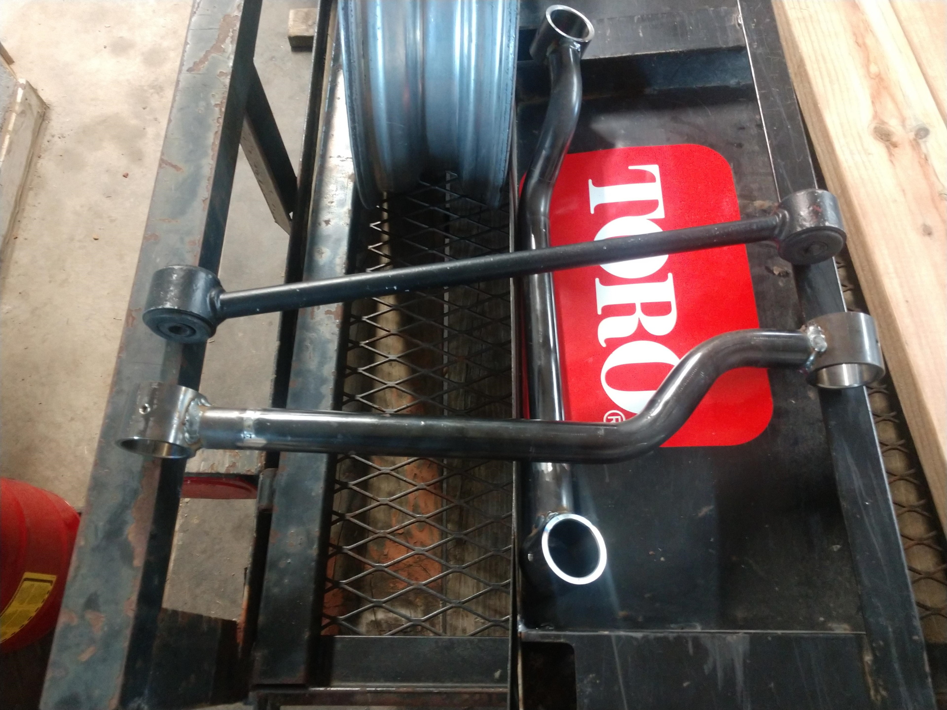
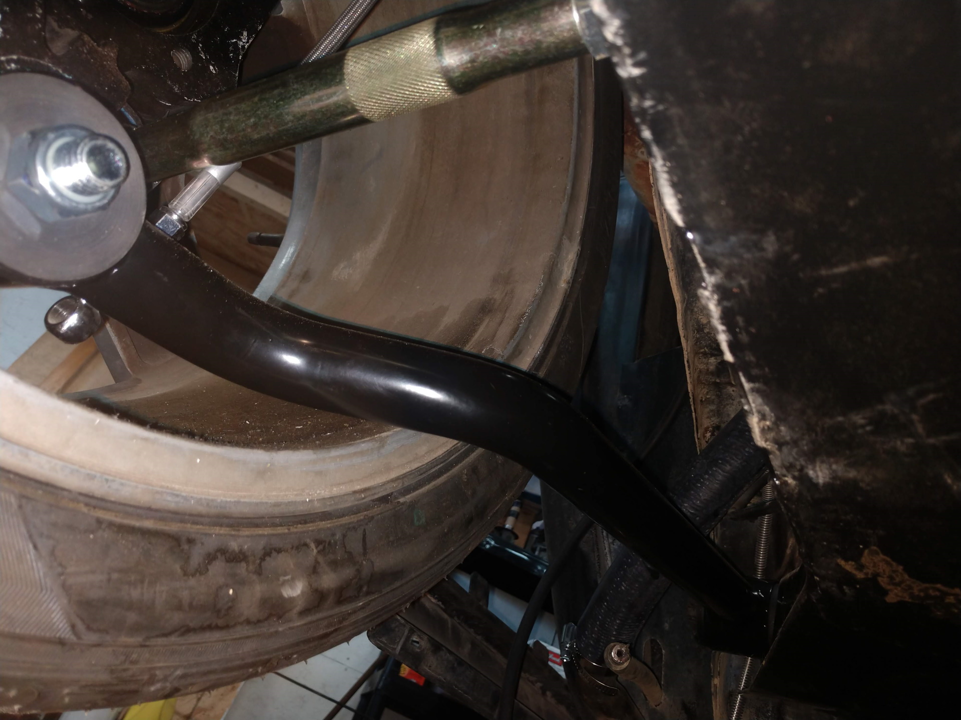
We are taking some scrap sway bars and making the forward link? not sure on the name. But it interferes with the rim. You can see in the pic that it will bump in toward the car and then turn and go forward.
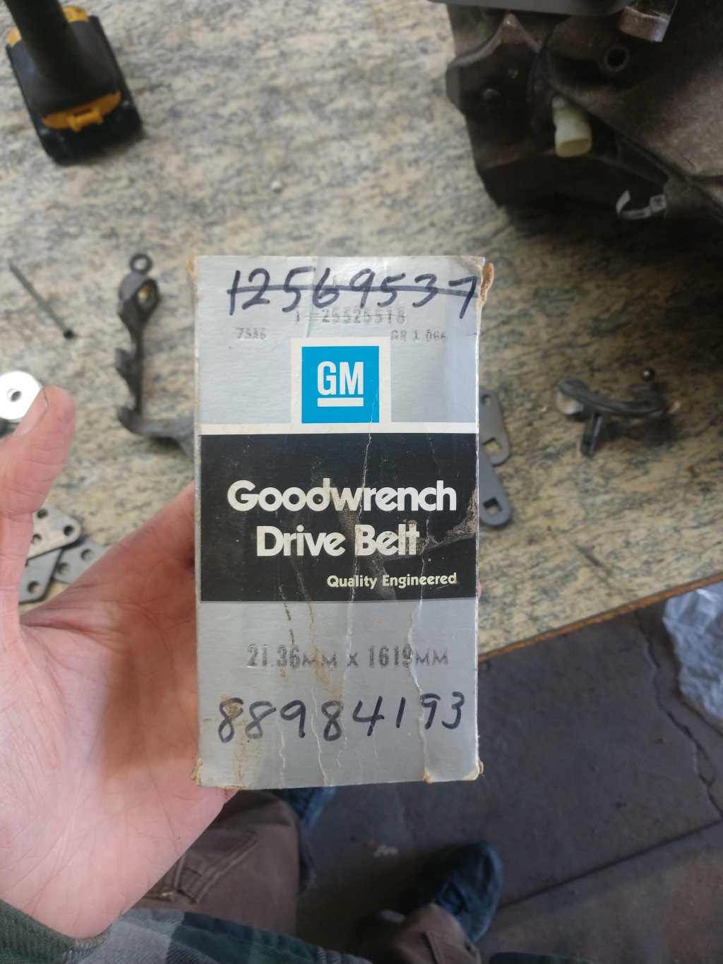
For part number reference. this is the belt that I ended using.
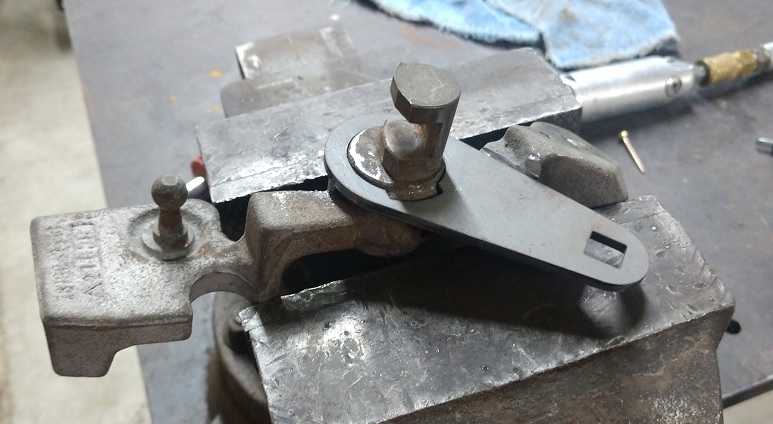
I started making a bracket for the shift and select cables. Here is the relocation of the select ball.
And the shift ball
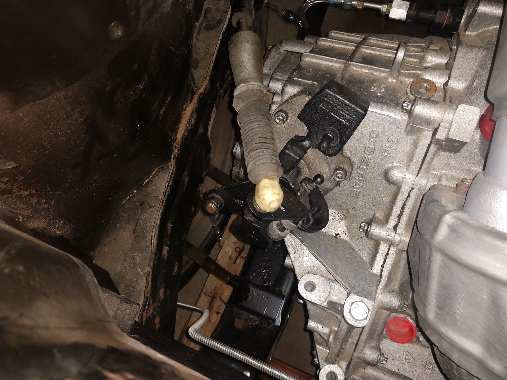
In the car.
Napa rotors are 880717 tires HTR Z III 285/30ZR18 245/40ZR17
I will try to update more but I took a new job that is more demanding, started taking night classes to get a degree and had my second kid last November.
That is awesome build. I enjoyed it. Thanks for sharing. look forward to hearing the about the the it performs. I love your set up. I wish I had that space!!!!
Nice work! you must have easy access to a laser cutter?
------------------ "I am not what you so glibly call to be a civilized man. I have broken with society for reasons which I alone am able to appreciate. I am therefore not subject to it's stupid laws, and I ask you to never allude to them in my presence again."
I wish I kept close records like I was in the past. With two kids and moonlighting I have a hard time finishing this project and taking detailed notes. I will just post some pictures and desctiptions.
First, I bought this fomula with no title. I know someone dumped $15k into it with NOS and new interior and SS fuel/brake lines and more. Then was neglected, broken into, and sat on a farm with no title for years. I should be able to get the title, as i found the registered owner after some research.
My tensioner/ dog bone mount. I might make some more to sell, but i would need to know what brackets they used for the engine, as mine were of my own design. I could sell it with the top part not welded and you could fit it and plug weld it.
Powder coated
Installed
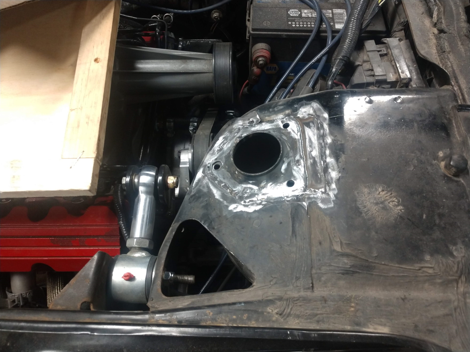
I used FieroGuru's tube idea to bring in the rear wheels. I found that the and links were for rock crawlers and not very durable. I went with some heavy duty ones from QA1. I can get the part numbers if anyone needs them.
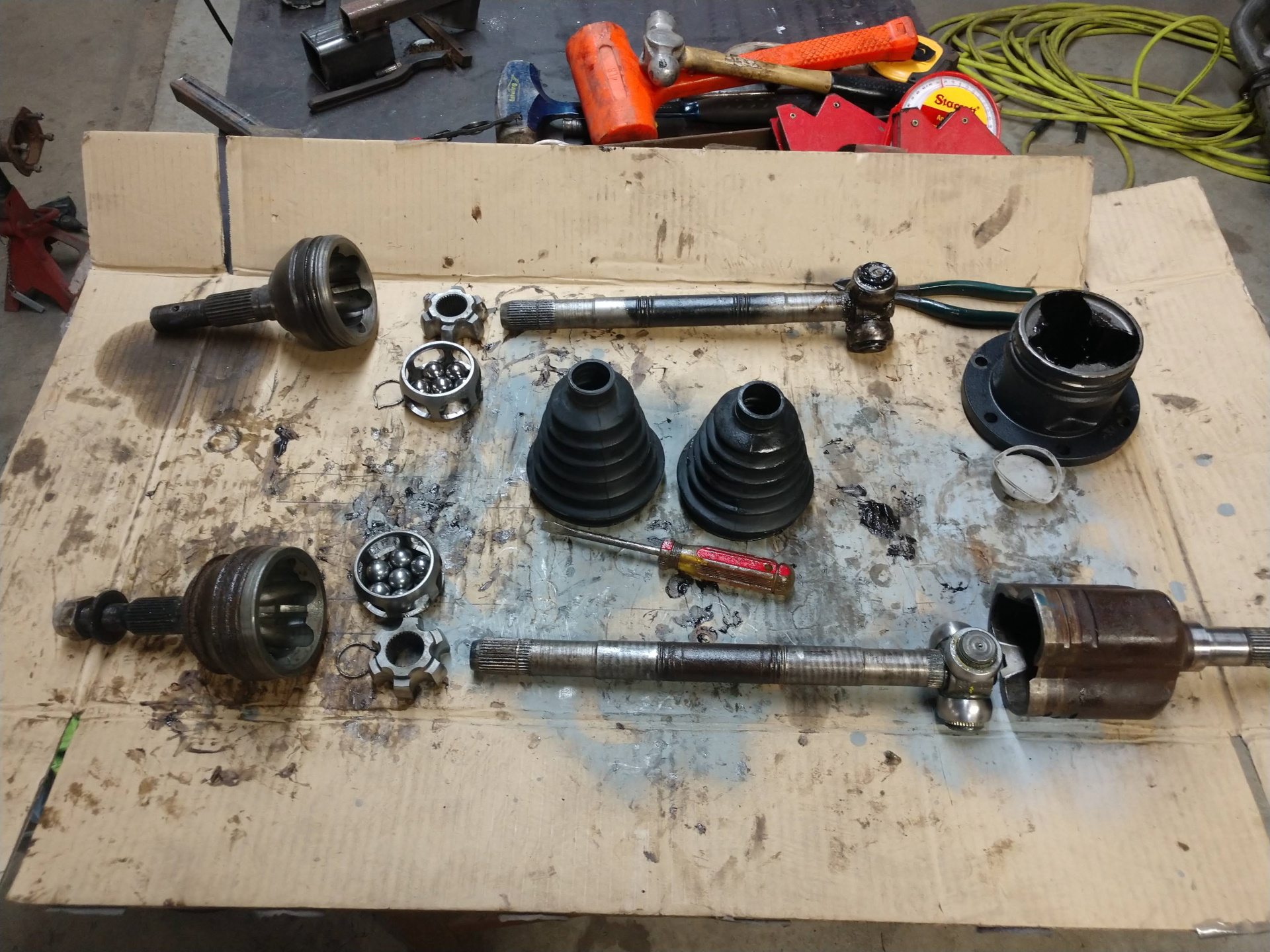
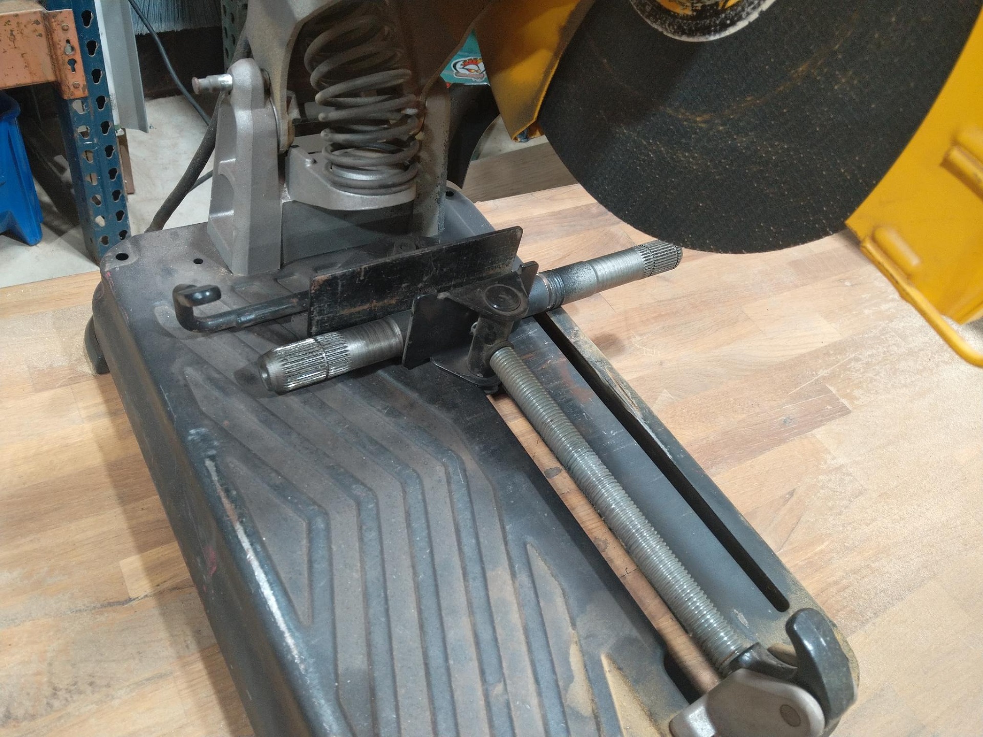
CV Axle fun. I think i am going to try to weld them and if it brakes i will order custom axles. The splines for the fireo inner and the S10 outer dont work.
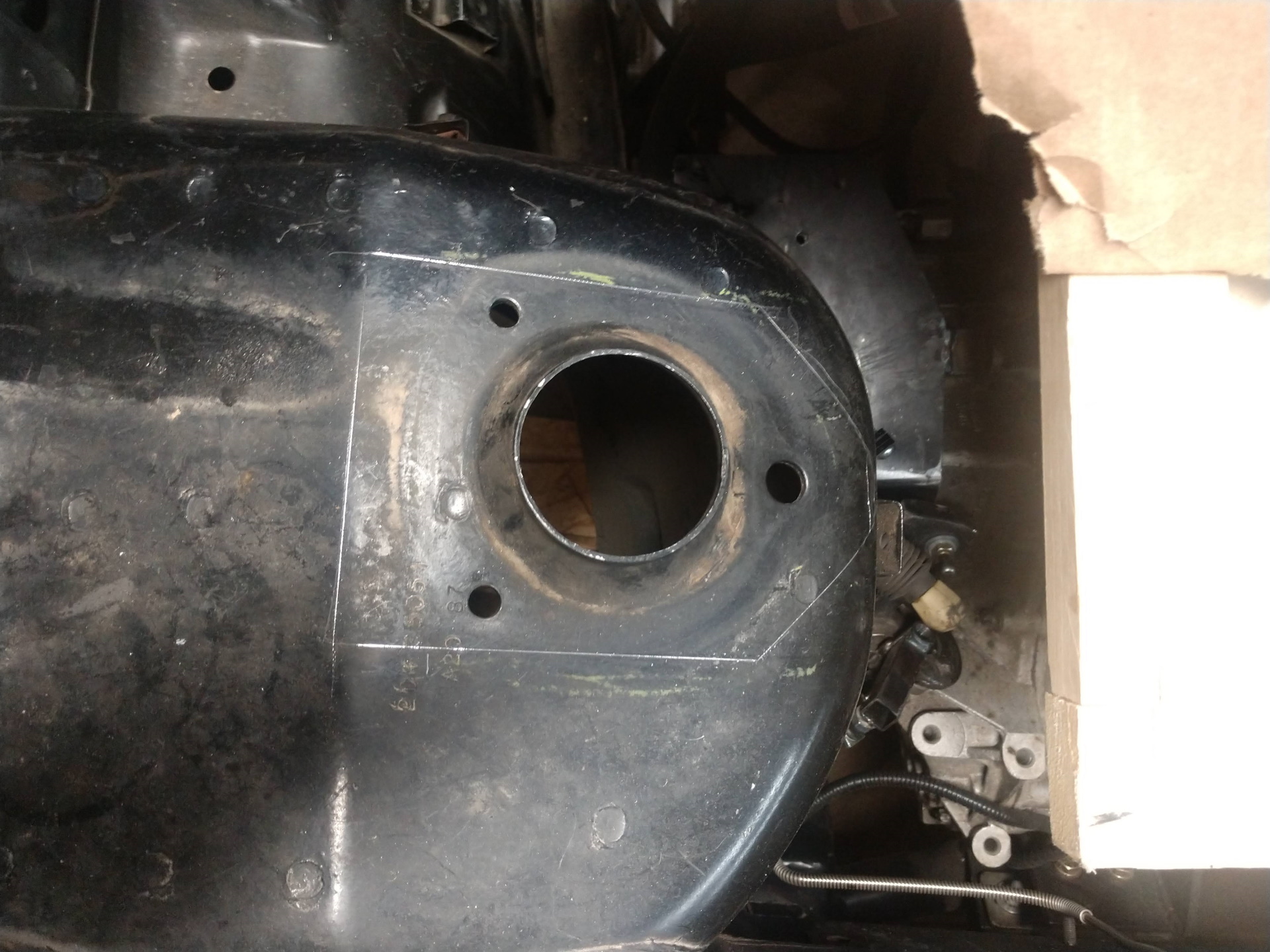
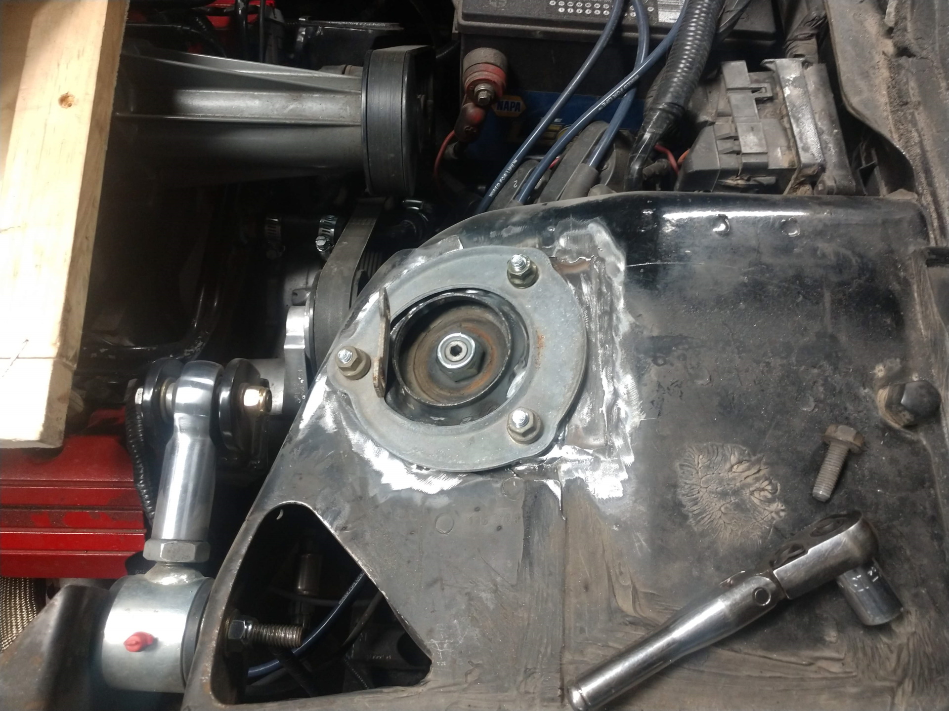
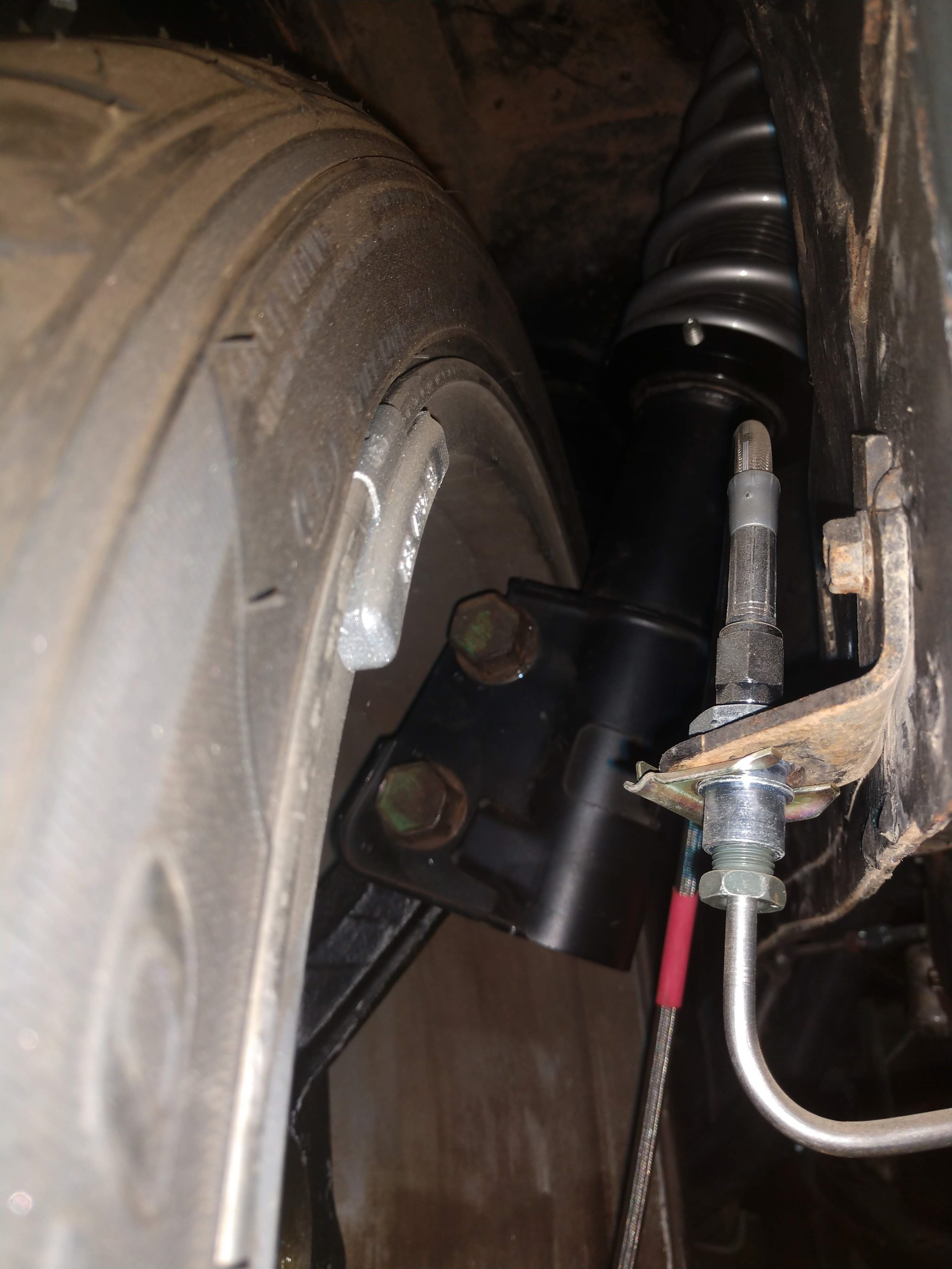
I had to bring in the strut tower mount 1"
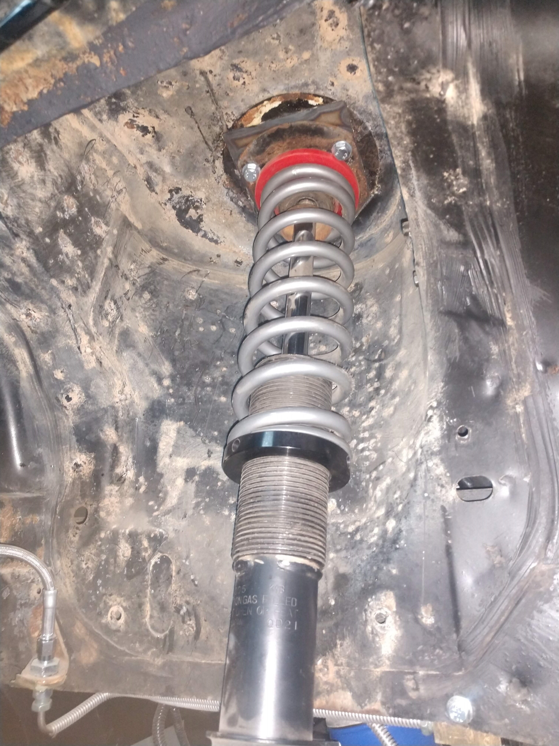
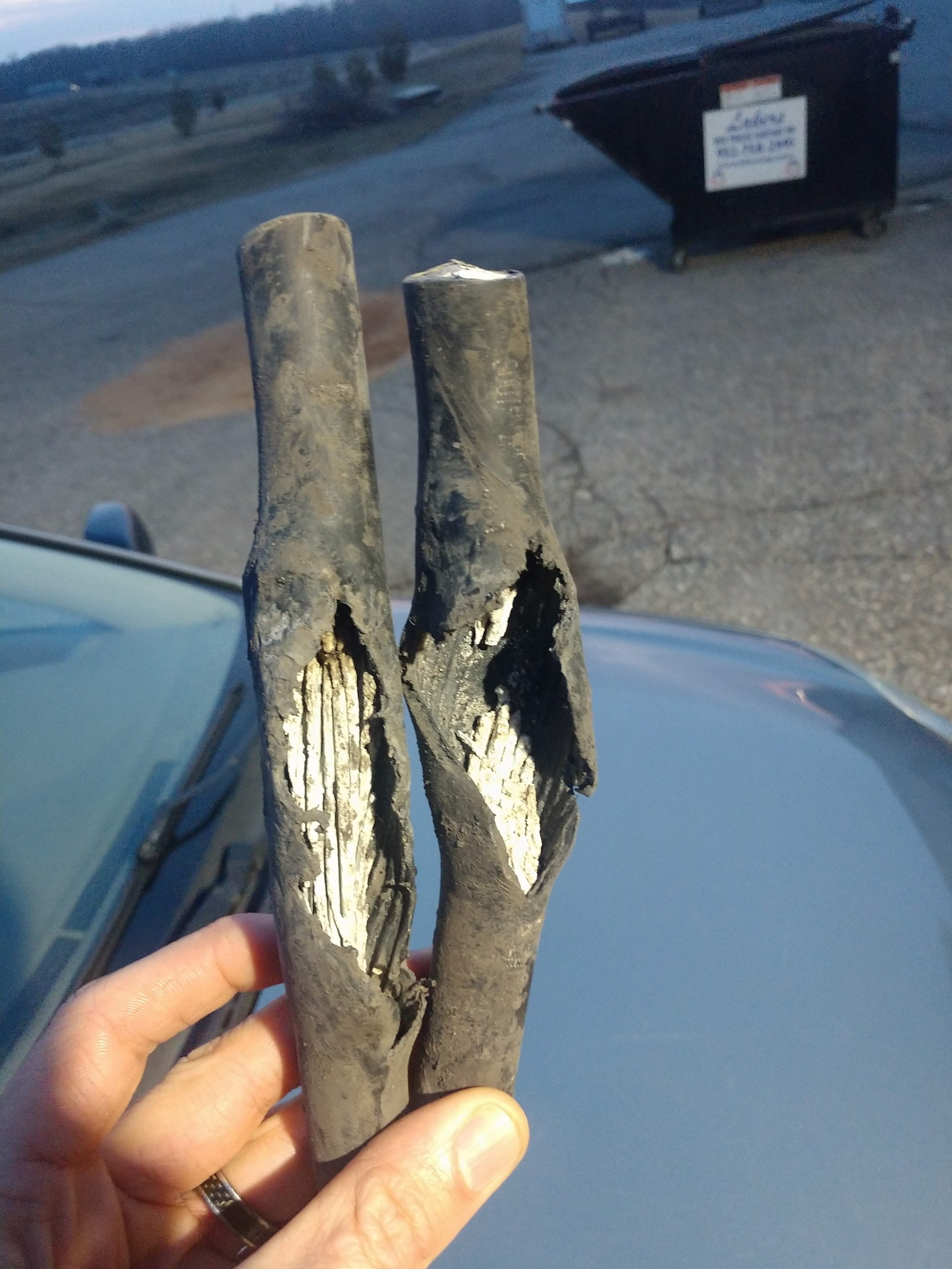
The rear wheels were too wide to clear the rear suspension bar (i cant remember the name...) So my dad grabbed a few scrap sway bars from the dumpster and i made new ones that will clear. Yea i know the strut is on backwards.... thats better
And the ISP is bringing in fiber this summer and hit my 600 amp service with a shovel last fall. When the spring melt came, the aluminum disintegrated.
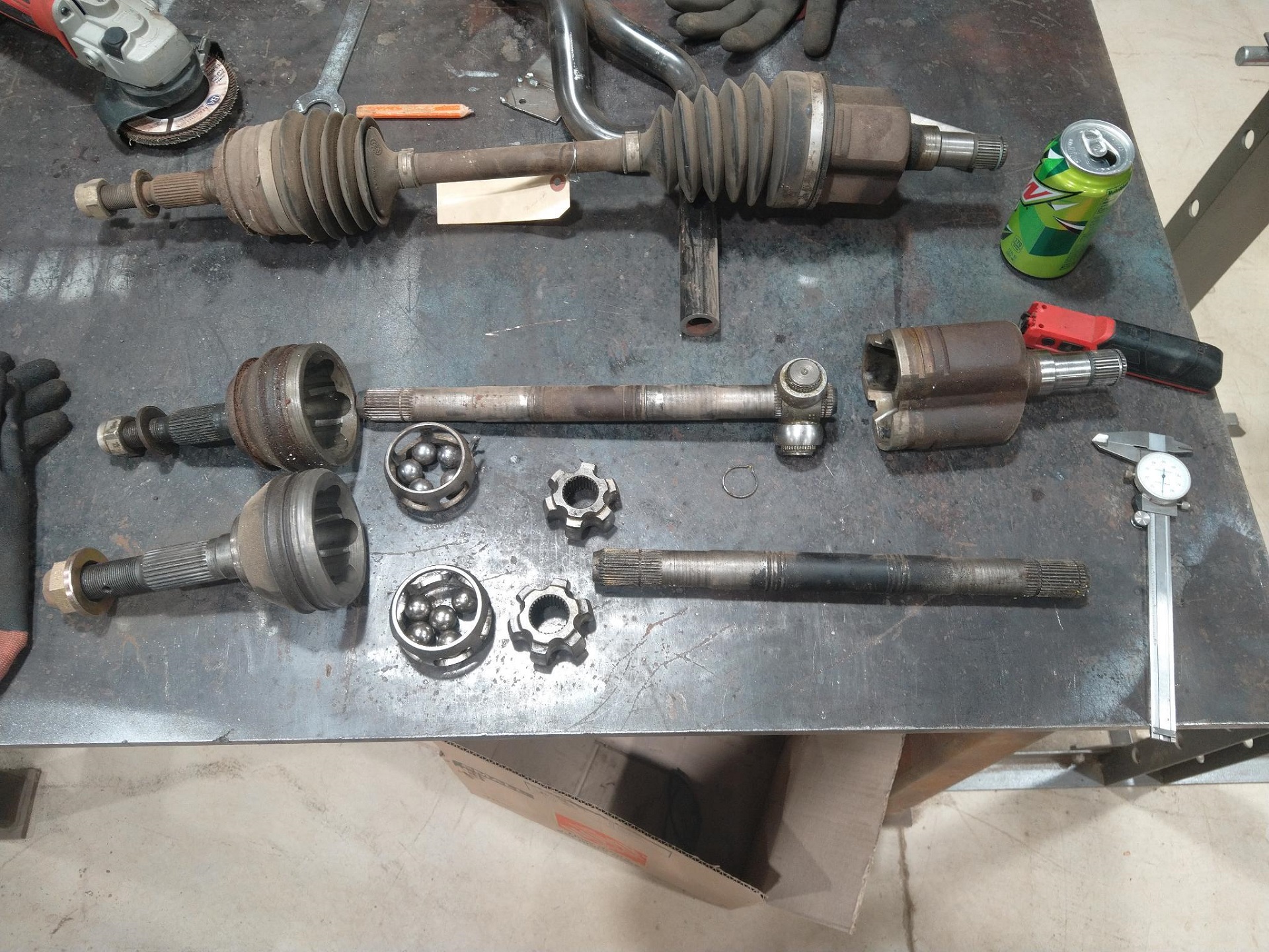
It has been awhile since I have posted. I have made progress on axles and brakes.
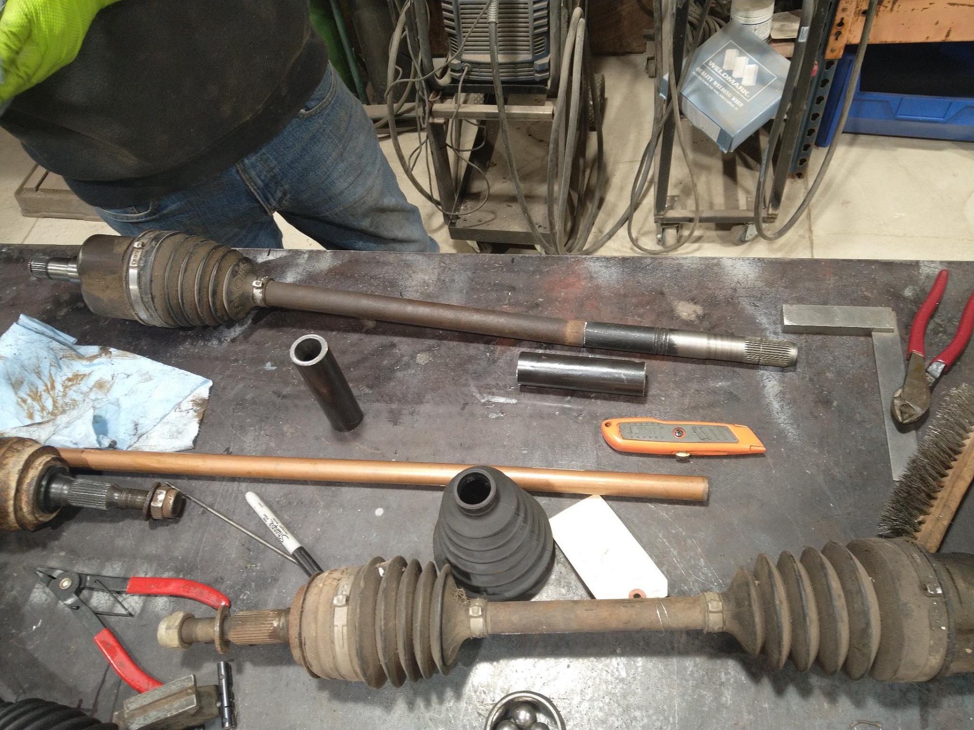
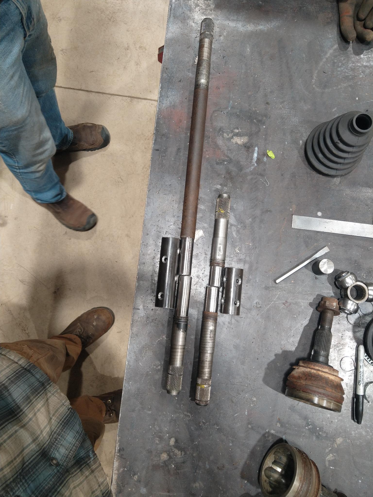
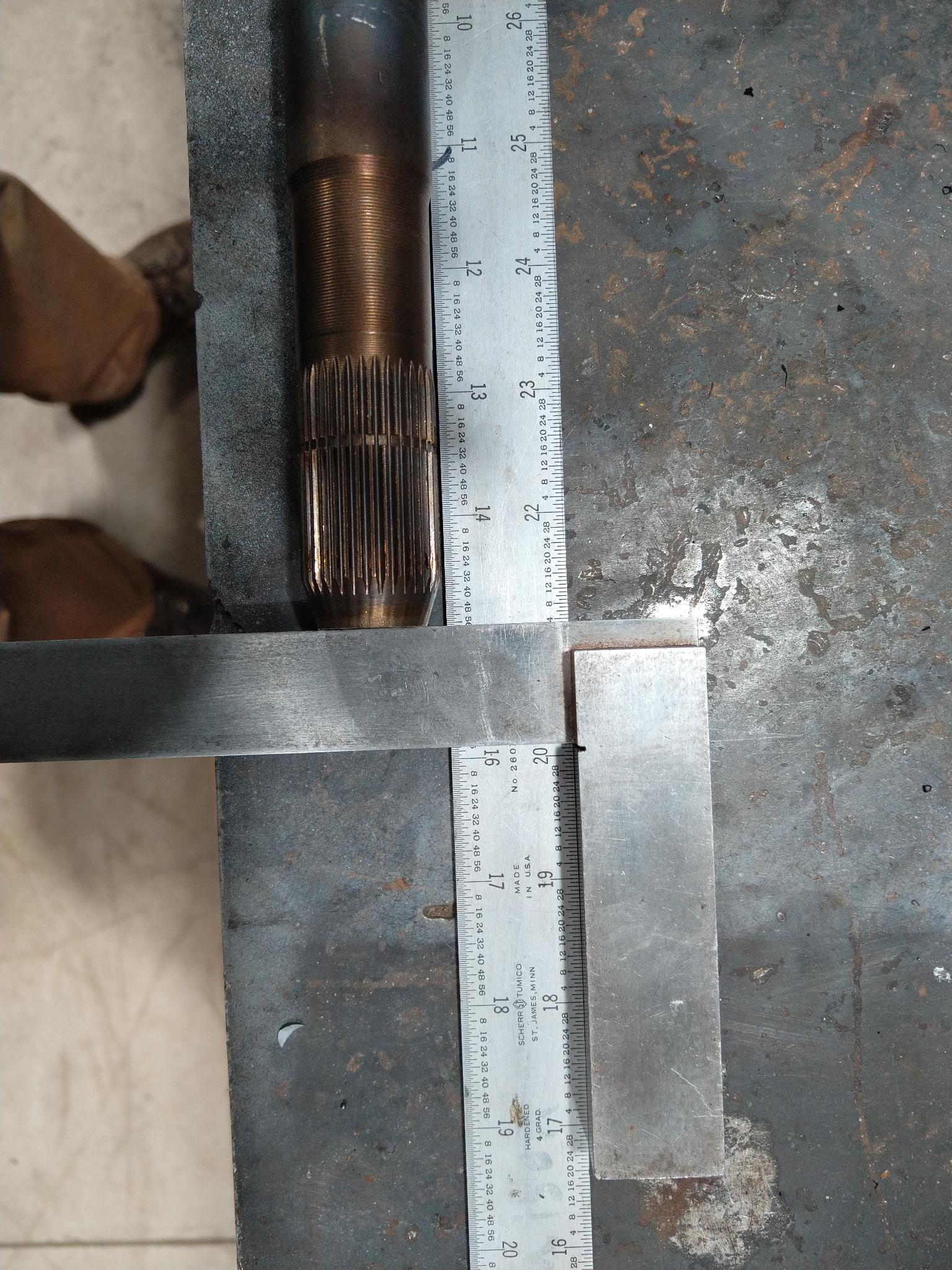
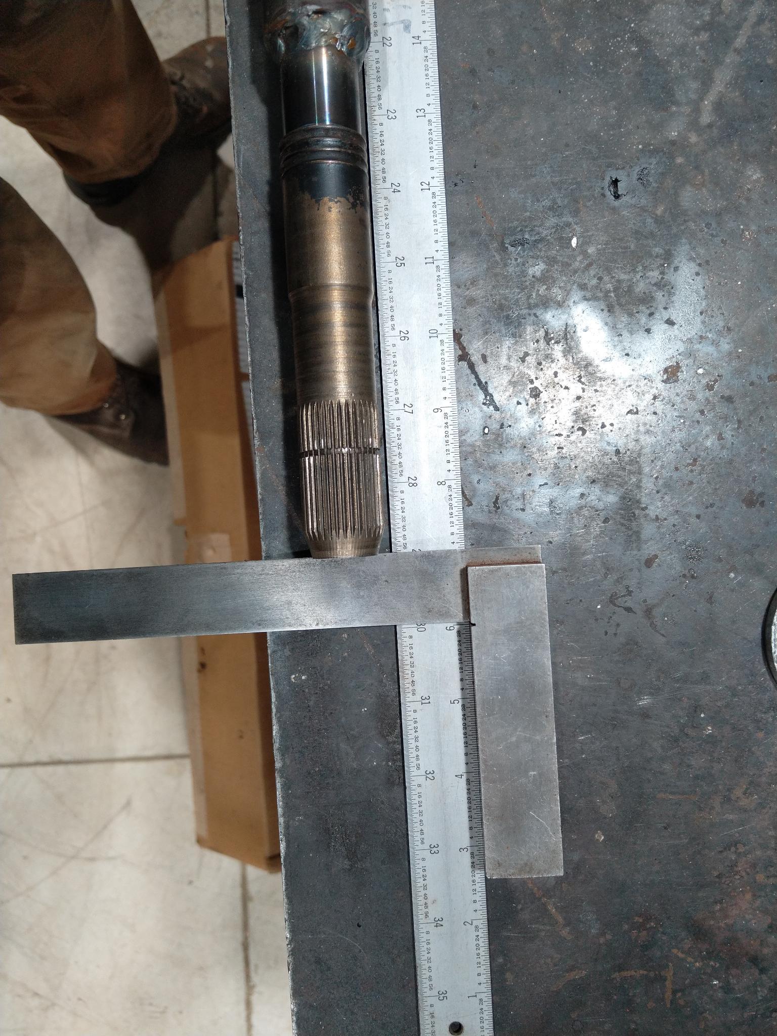
I took the inner cups and shaft from a 88 manual fiero and the outers from a early 90's S10. I tried to get them so they are in the cups deep, but not to bottom out.
I had a machine shop turn down the axles and center the inside of the tube. The tube is actually from a scrap sway bar at QA1.
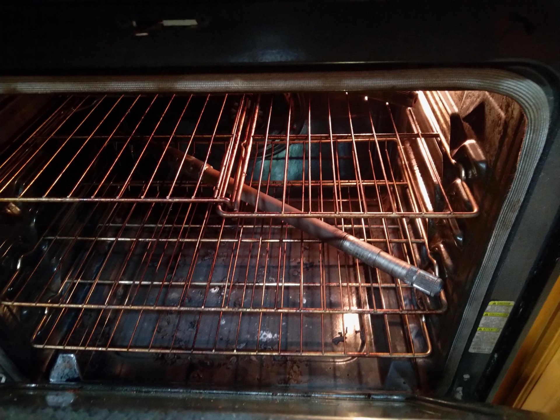
I am not sure it helped, but I threw it in the oven after welding to let it cool slowly.
Drivers side
Passenger side
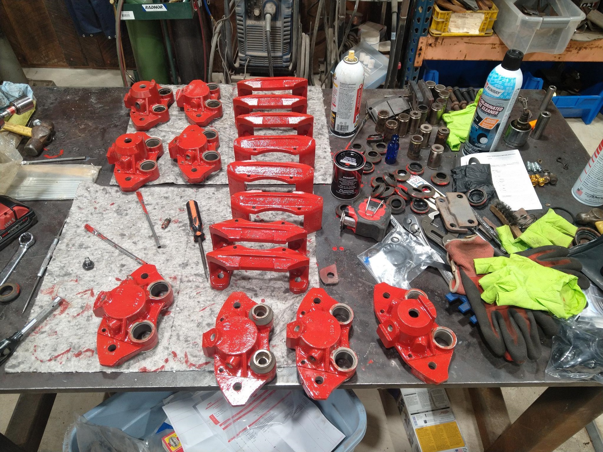
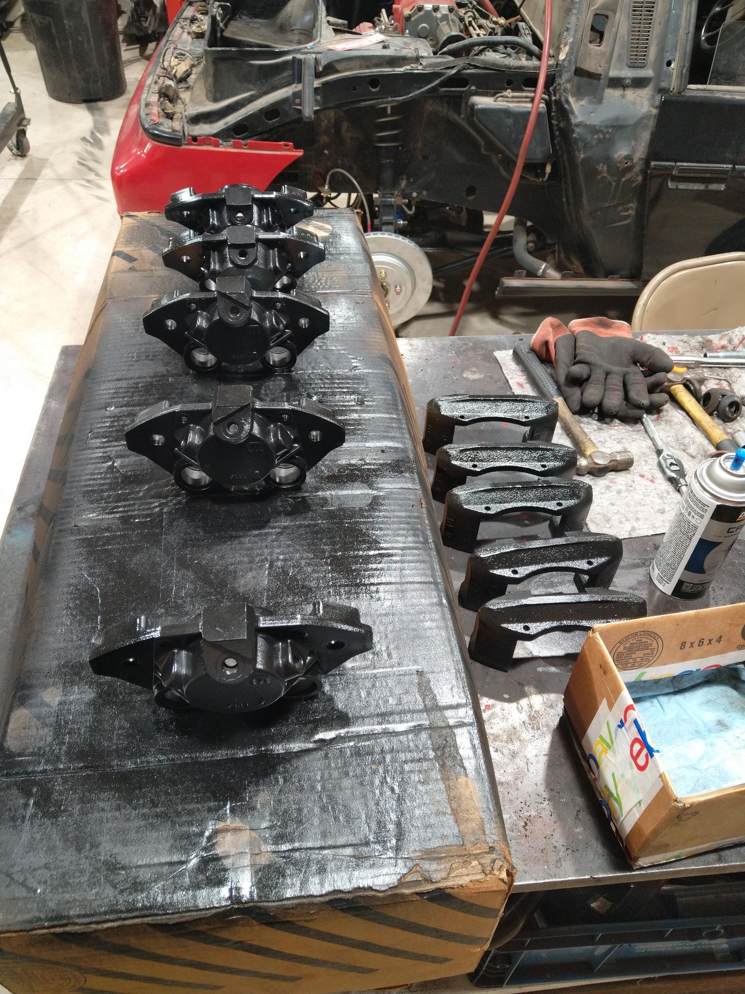
Brakes I found a few extras from the parts are I bought awhile ago.
I decided to do my stock 88 fiero brakes too.
I found that the rear inner seal was bad in 3 of 5 rear calipers. I found a guy in FL that had a few extra kits. I also have the formula fiero that probably has bad seals.
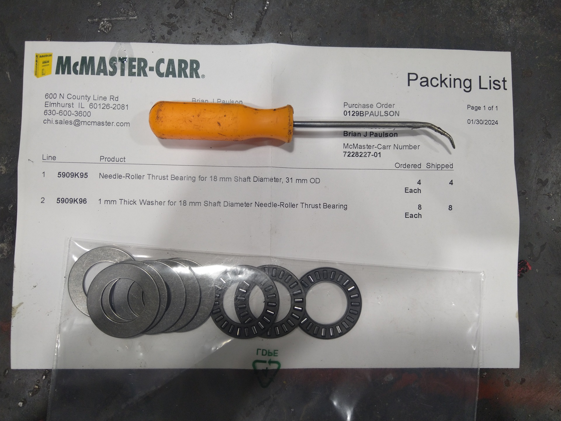
I found that disassembling the inner pistons the ball bearing (three balls isn't really a bearing) were prone to cracking upon reassembly. I bought some very close ones that just needed to be turned down a little.
Here is some pictures of the brackets for the breaks.
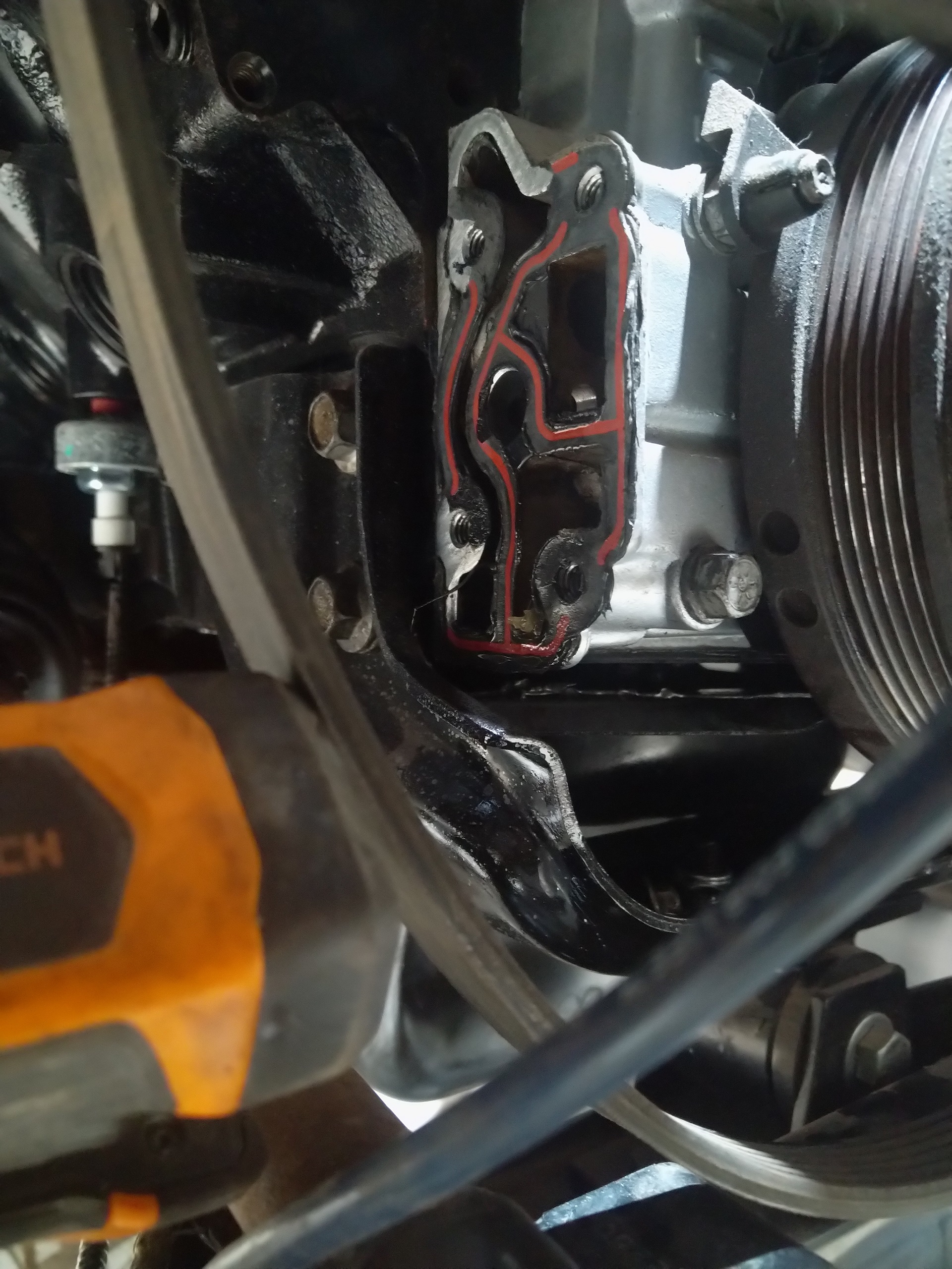
I then had decided to bleed the coolant. I had the engine running then noticed no oil pressure. I tried filling the engine with 9 qts, to get the level high enough to be in the oil pump, but it didn't work. I tool off the oil filter adapter bracket and the oil was dripping out. I was about ready to pull the timing cover to inspect the actual pump. But I had someone mention the high pressure oil relief valve. I found that I had not installed it. I bought the ZZP kit https://zzperformance.com/p...lume-kit?zCountry=US
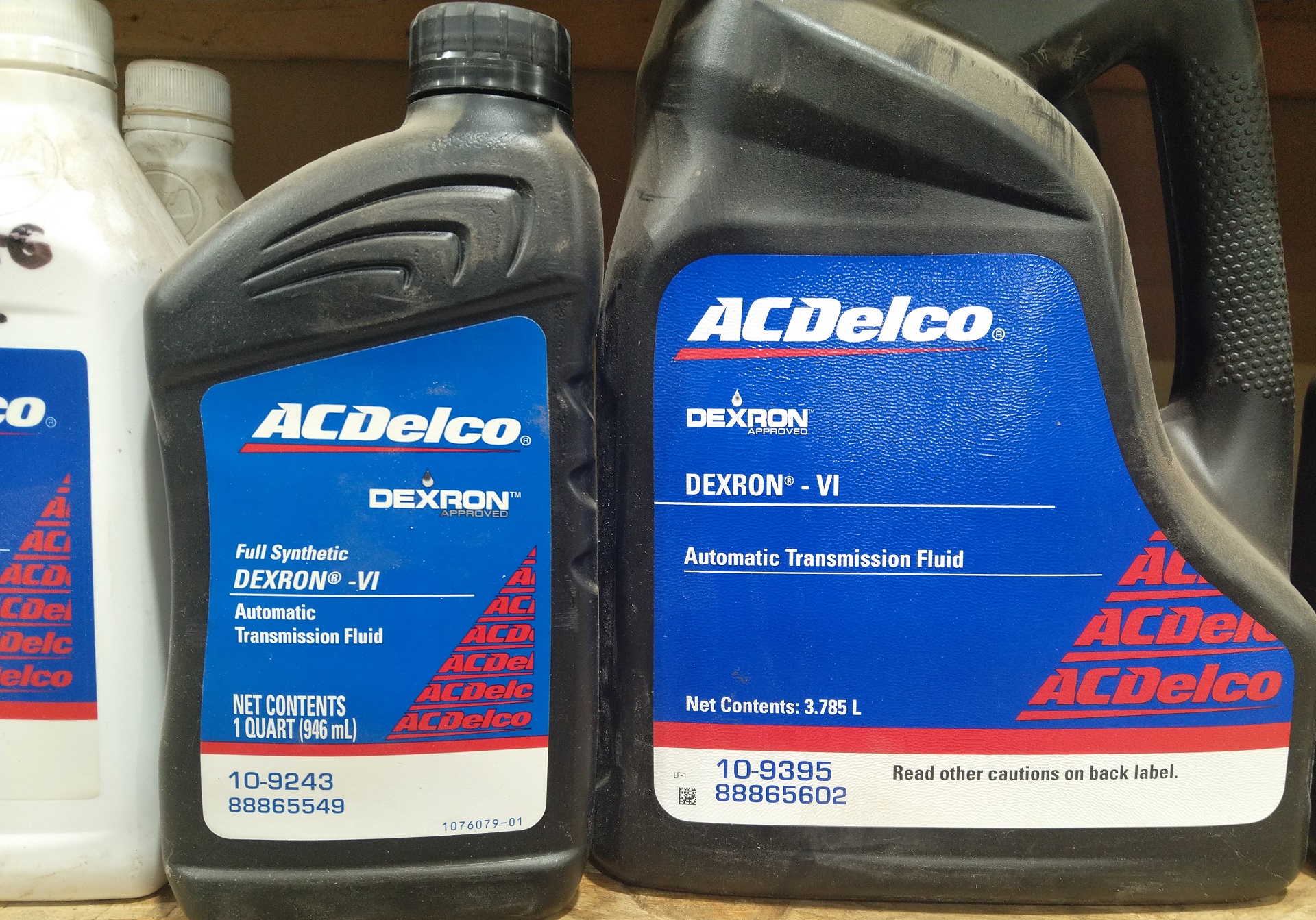
I filled the F23, but I had a hard time finding the difference between these two GM part numbers, but I suspect its the quantity. 10-9243 88865549
and
10-9395 88865602
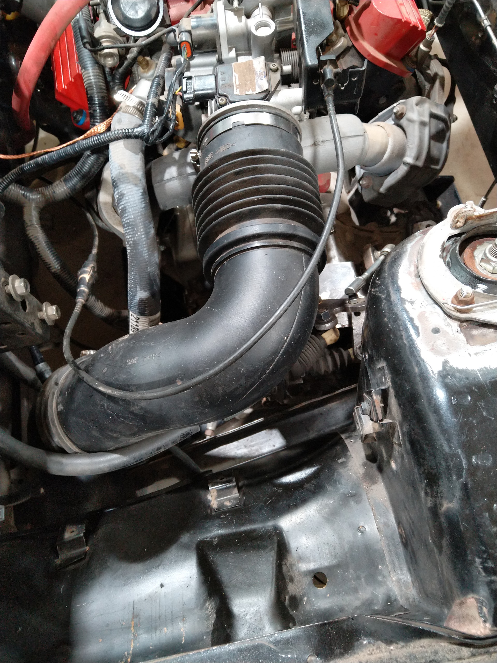
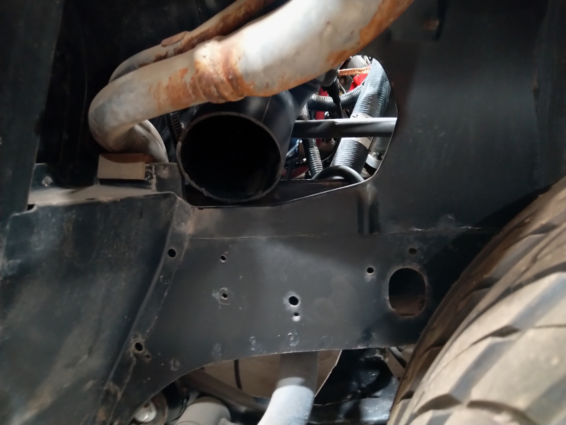
Intake installed. GMT800 (1999-2006 Silverado/Sierra 4.3L) air induction tube cut to fit, using a K&N filter mounted in front of the left rear wheel in that space behind the inlet grate. K&N Universal Clamp-On Air Intake Filter: High Performance, Premium, Washable, Replacement Filter: Flange Diameter: 3.5 In, Filter Height: 7 In, Flange Length: 0.875 In, Shape: Round Tapered, RU-3130
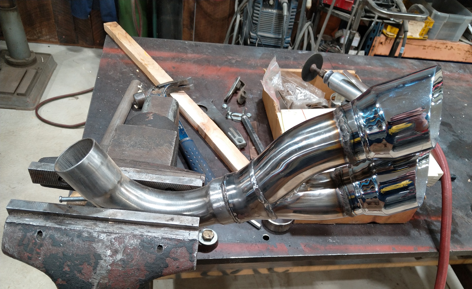
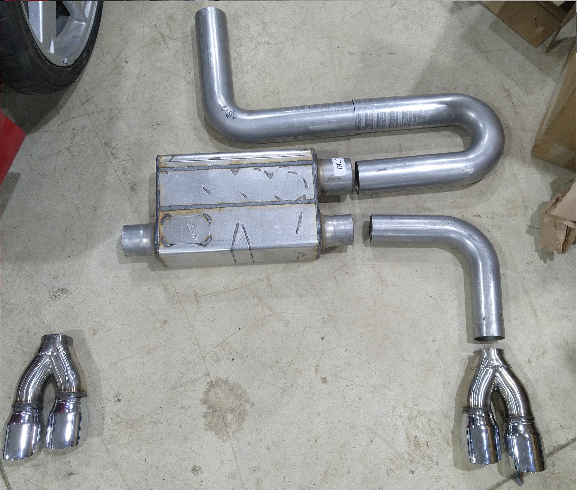
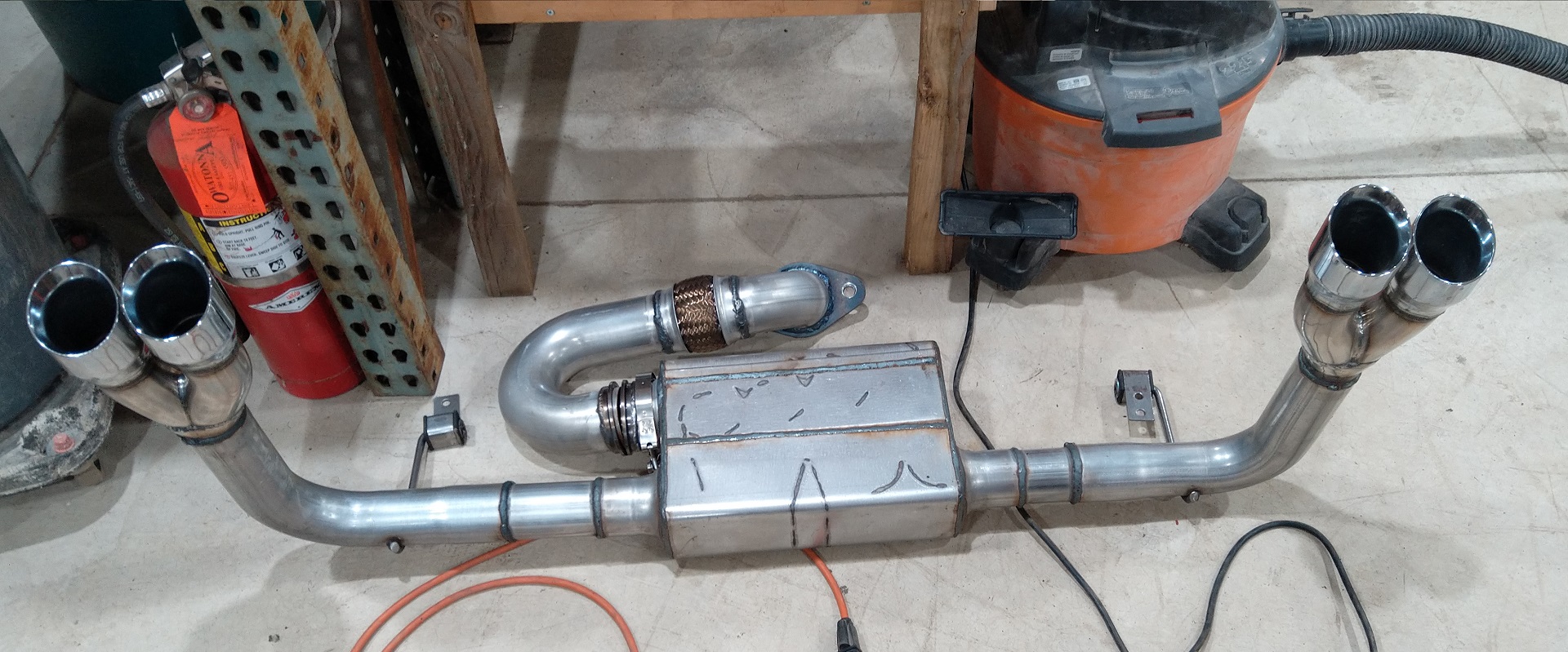
Exhaust.
I am doing 3" into muffiler and dual 2.5" to splitters. The stainless tips are 2.25, so I am cutting off the 90 degree bends.
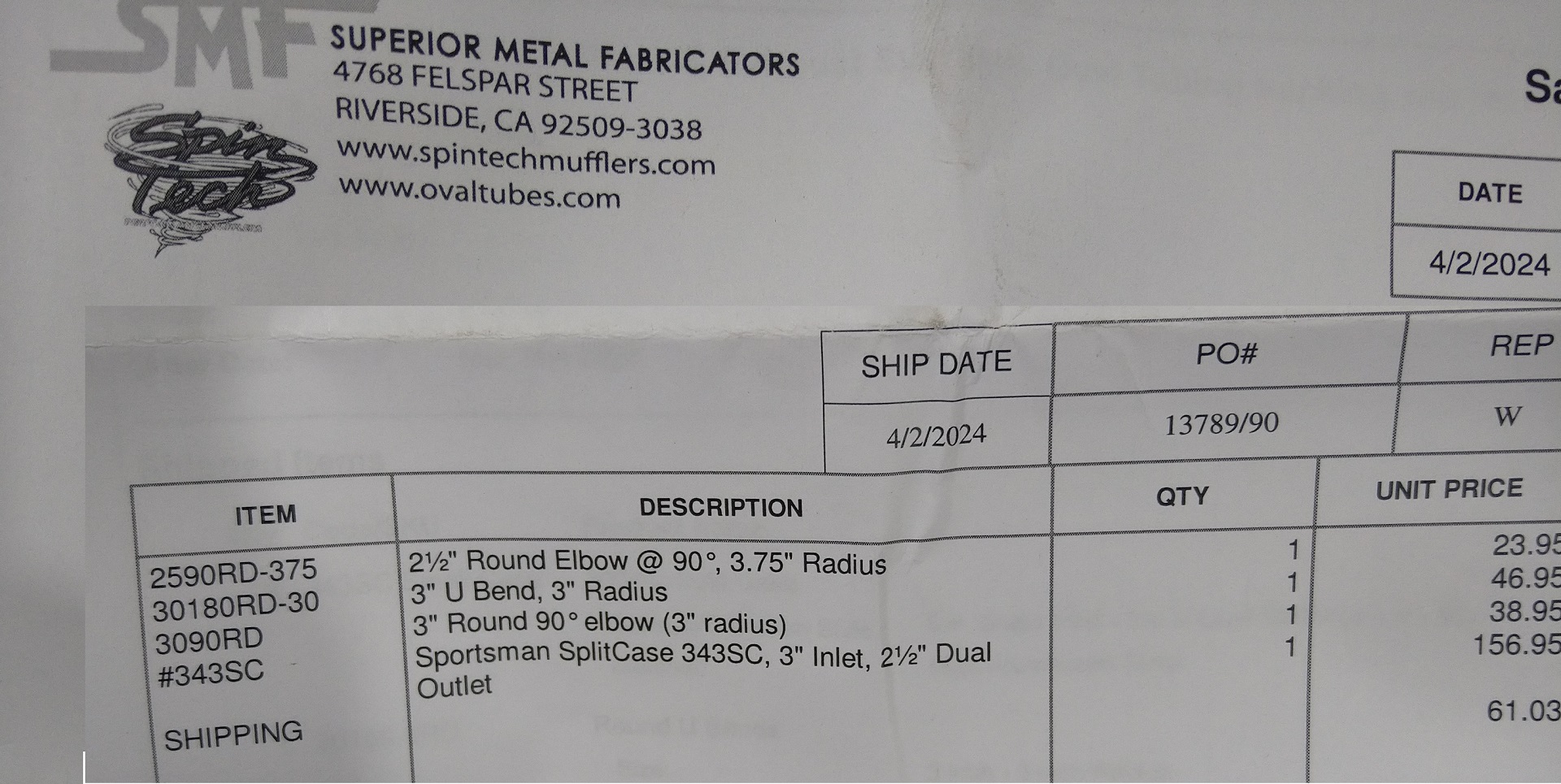
Parts list from Spintech. I forgot one 90 degree bend, that you can see.
It was $700 labor to get this done at Midas in Shakopee, MN
I will be doing exhaust wrap next post.
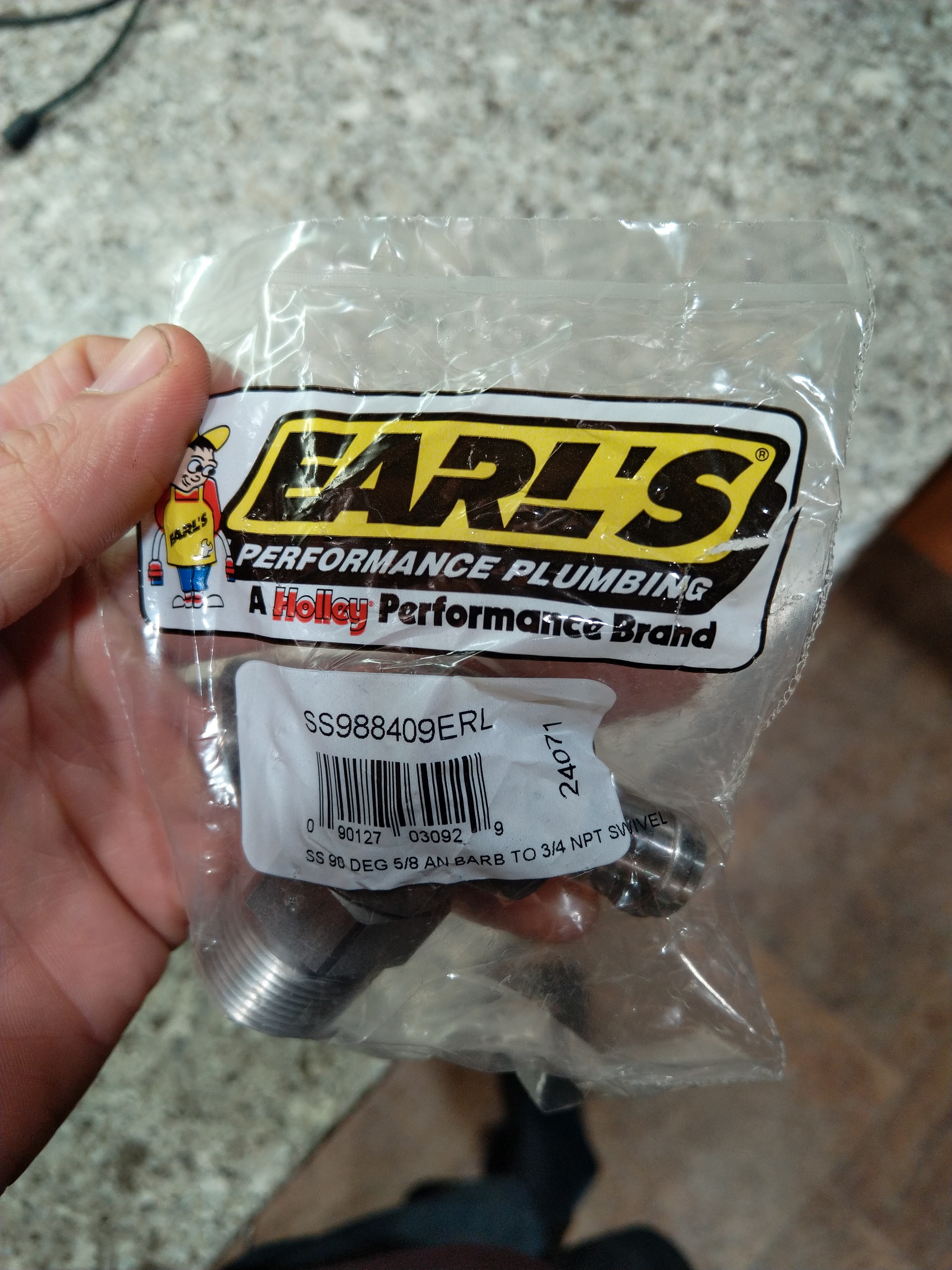
The coolant update. I changed to this 90 degree swivel off the LIM. It was not cheap and I almost didn't get it.