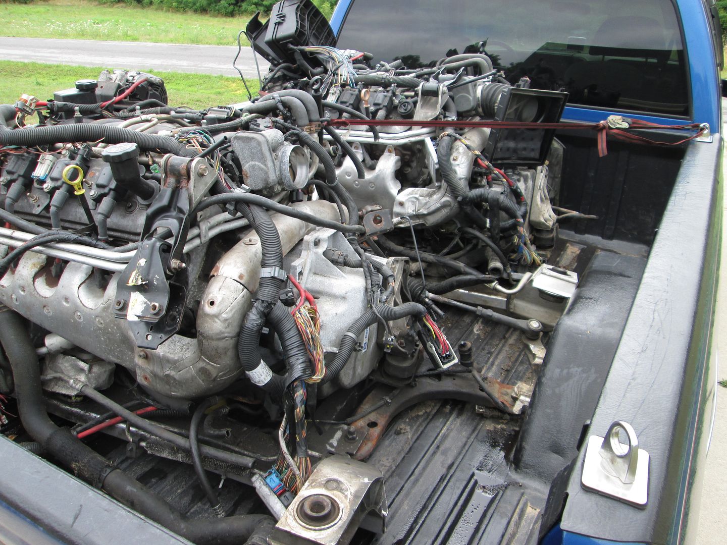
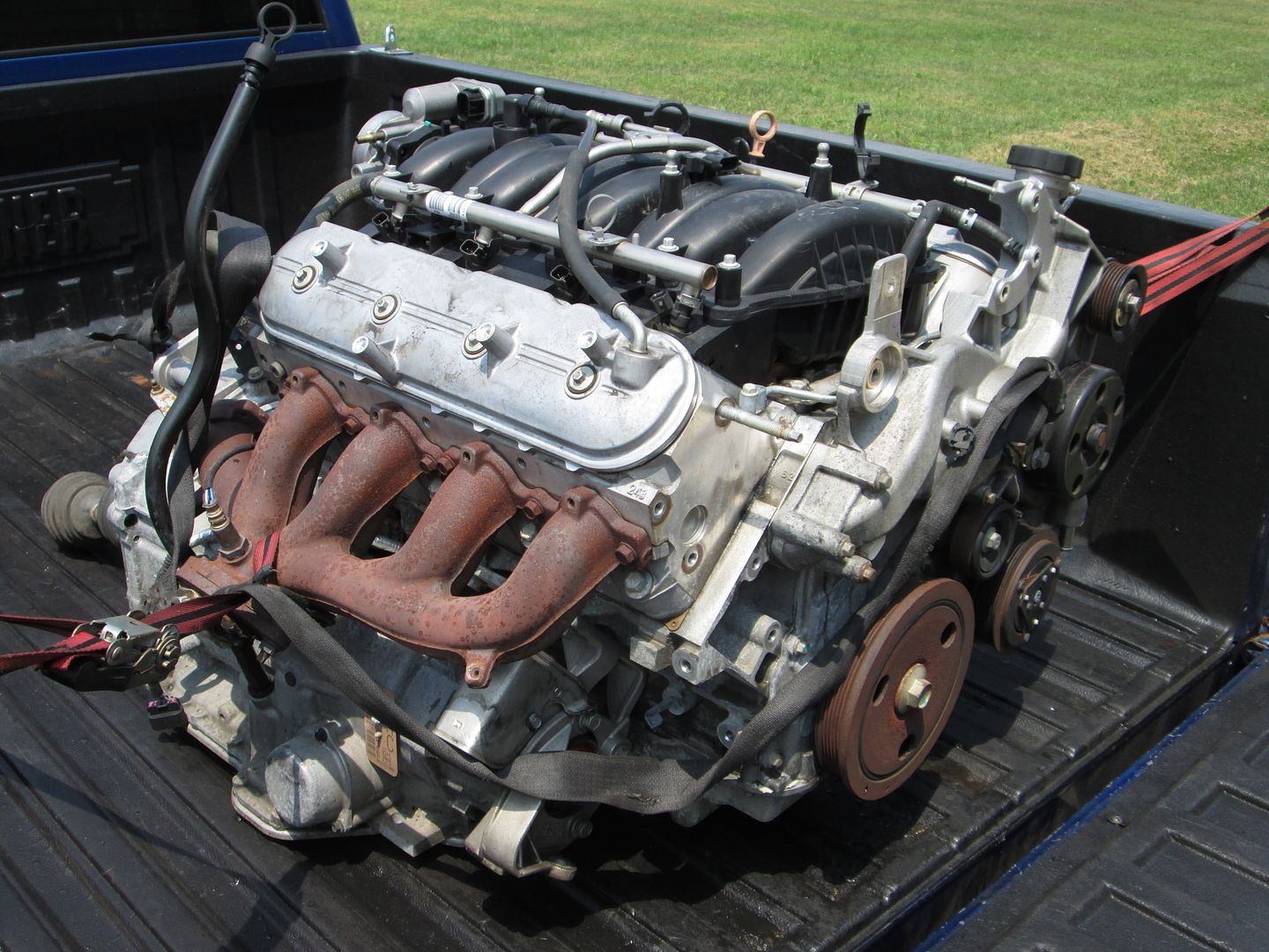
A couple of weeks ago, I picked up two LS4 dropouts,. I was looking for one to start another LS4/F40 swap, but I was able to work a good deal on both.
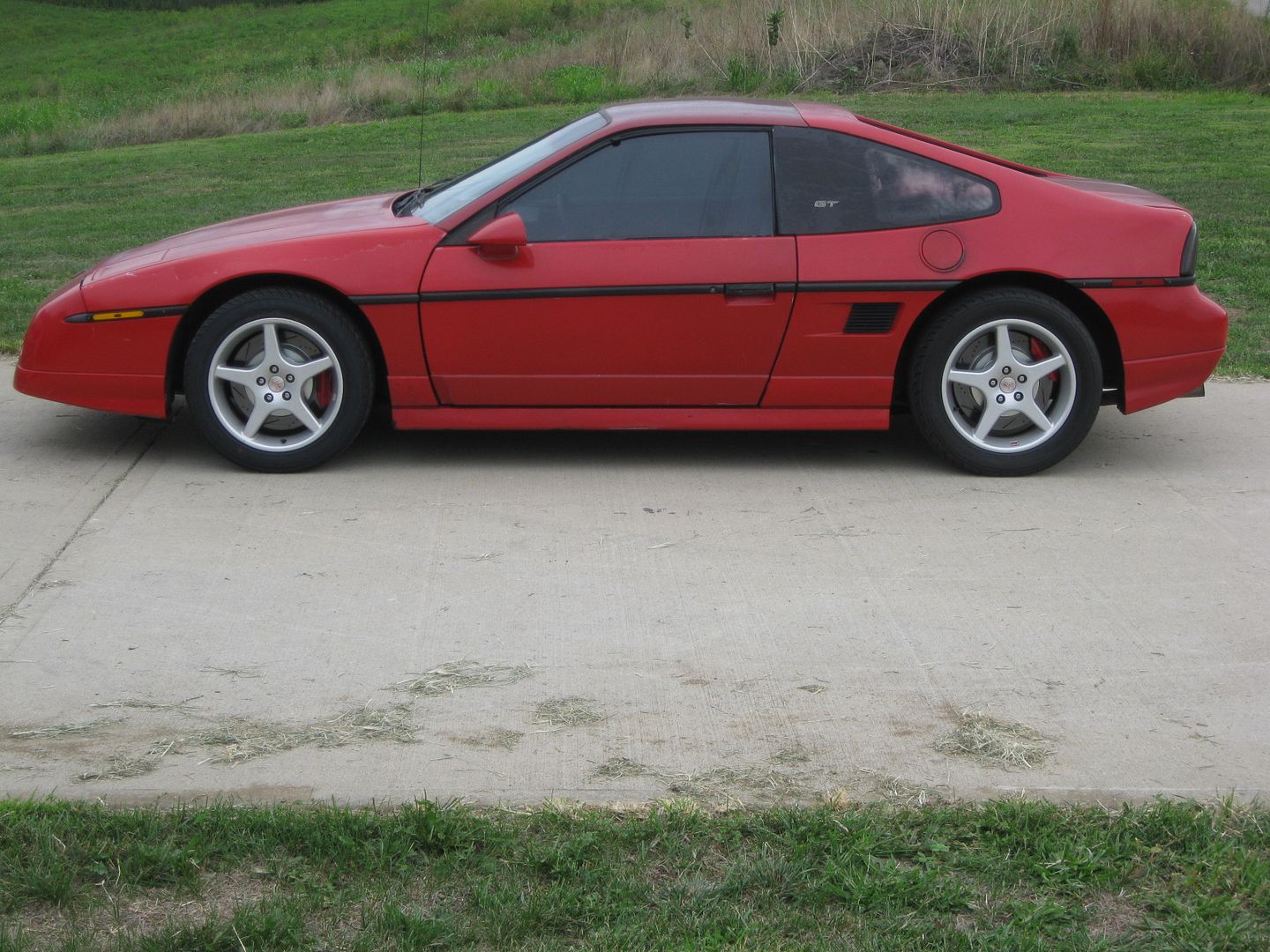
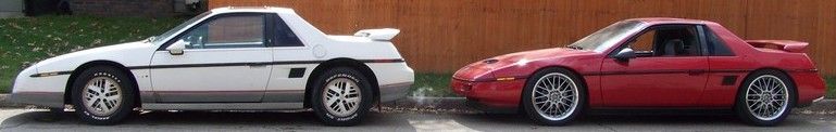
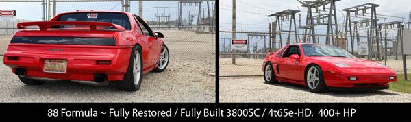
So I have decided that the one from the 07 Impala SS will be an automatic swap. The tentative plan is to do the swap in my 88 GT Clone that is currently a 4cyl/125C:
A few ground rules for the swap...
1. No performance upgrades. This swap is more about better understanding the similarities and differences between the Auto and Manual LS4 swaps, so it will stay bone stock from MAF all the way through the exhaust manifolds. 2. Keep things simple. I would like this swap to be something that others could do on their own. 3. Custom parts will be kept to a minimum but there will still be several: mounts, alternator bracket, harness (stock 203/500 connections), exhaust, etc. 4. Once the swap is done and I have used it for what I need it for, I will likely sell the car or the swap as a dropout for someone else to play with. Sorry, no calling "dibs".
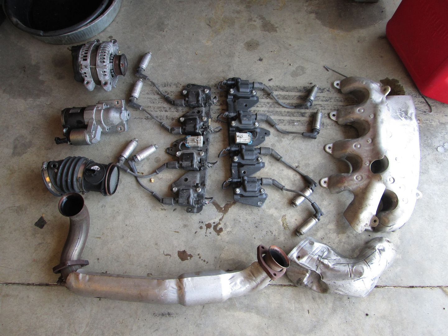
First order of business was to remove all the crap that I won't be using:
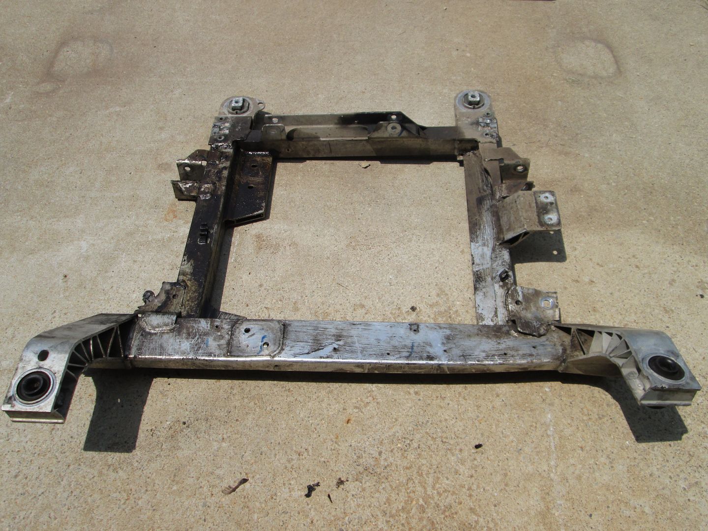
In case anyone wants to know, the aluminum cradle as shown weighs 42 lbs. Stock 88 cradle is 50lbs.
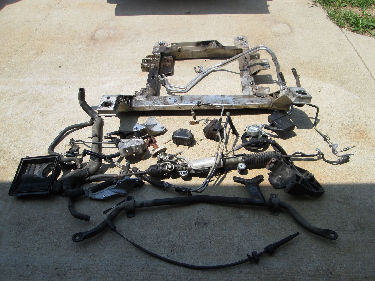
Here is the pile of parts that will be reused:
Then it was off to the car wash to clean it up some. Here it is after it dried in the sun:
Originally posted by FieroMaster88: Going to sell a swap kit in the future?
This swap is more geared towards a how-to for the DIY group, but as I develop parts for this swap, I may offer them for sale depending on time/effort/cost for each one.
So a swap kit certainly isn't the goal at this time, but I will likely offer a few parts for this swap... especially if the parts can be common between the Auto/Manual versions.
quote
Originally posted by Nebiros88: Will you be keeping the AFM?
I am not removing it from the engine, but it will not function in the swap. The 07+ LS4 require the BCM to be wired up for DoD/AFM to work and I am not going through the added work to wire up the BCM.
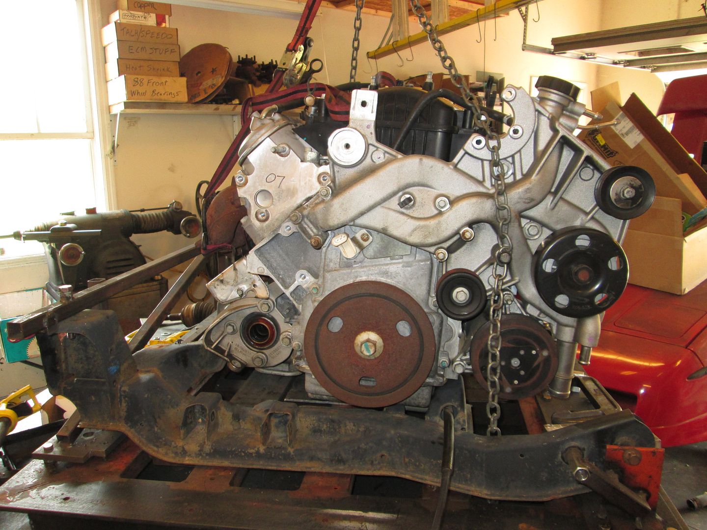
I went ahead and mounted the 88 cradle to my fixture and set the LS4/4T65e-hd onto the cradle. It won't even fit between the cradle right now as there are interference issues in multiple areas.
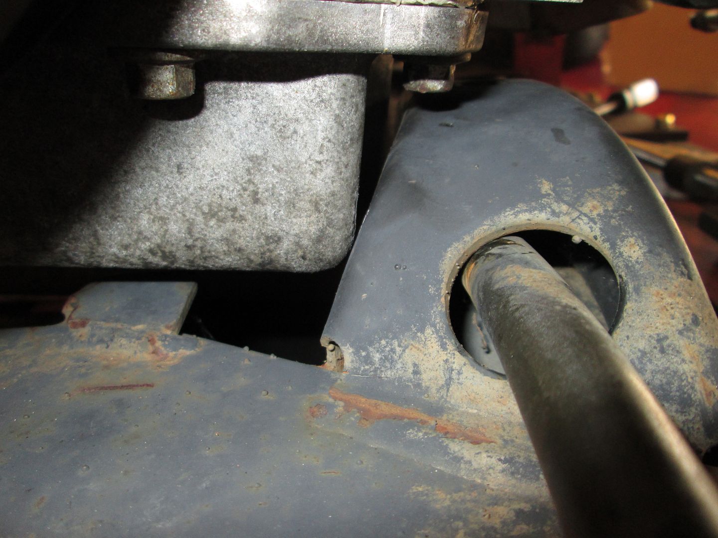
Starting at the pulley side, the front cross member tapers out some as it attaches to the cradle, this tapered portion is hitting the side of the oil pan.
The stock 88 engine mount pad interferes with the oil pan as well. It will either need to be notched on that side at a minimum.
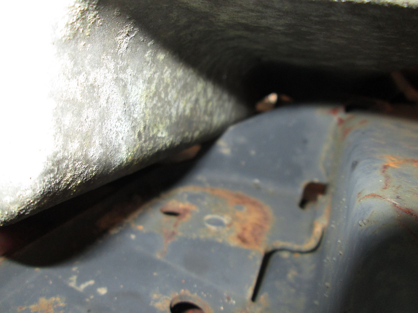
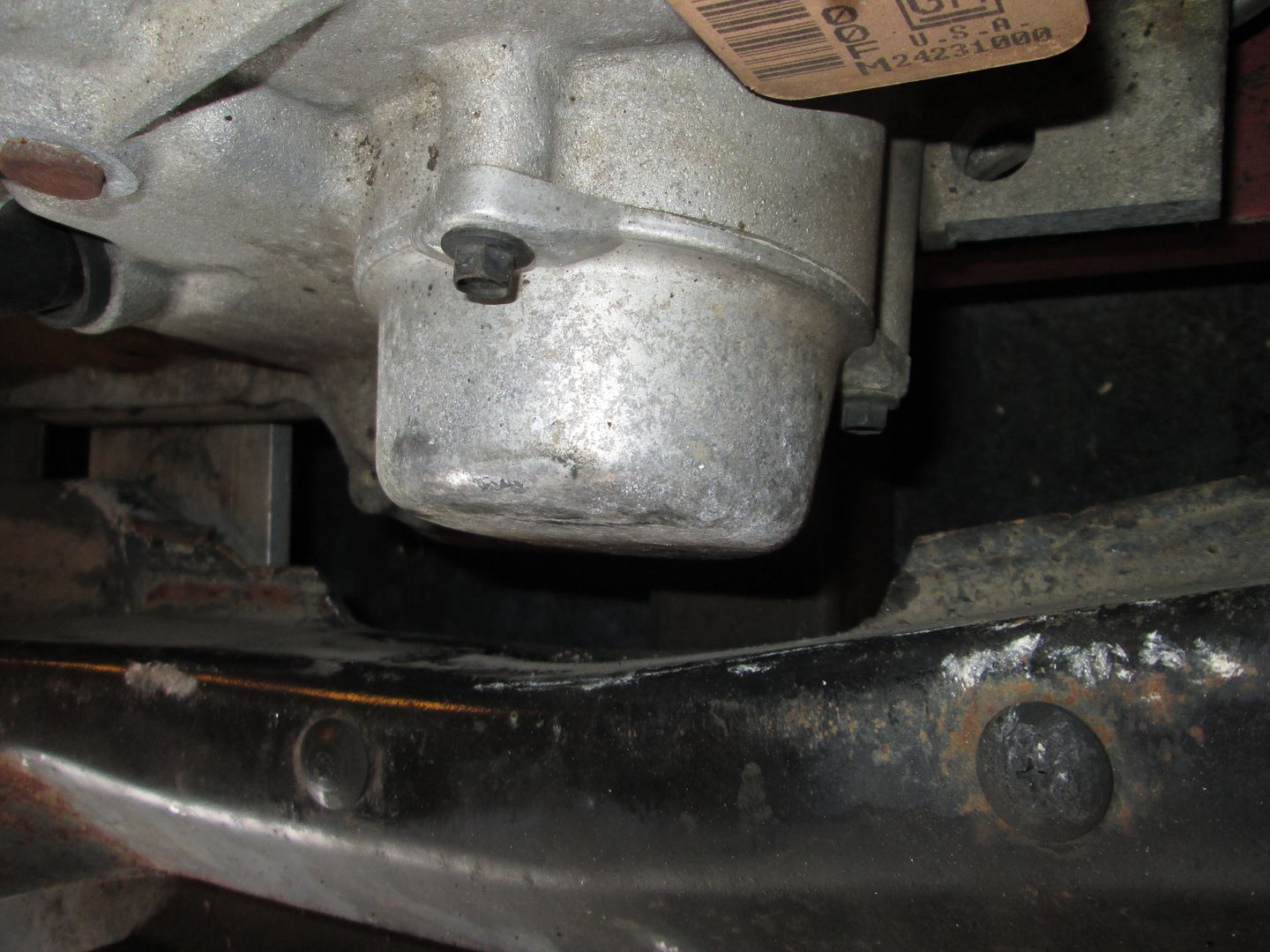
The protruding portion of the transmission will not clear the lip on the rear crossmember. The lip will need to be removed and the seam welded up.
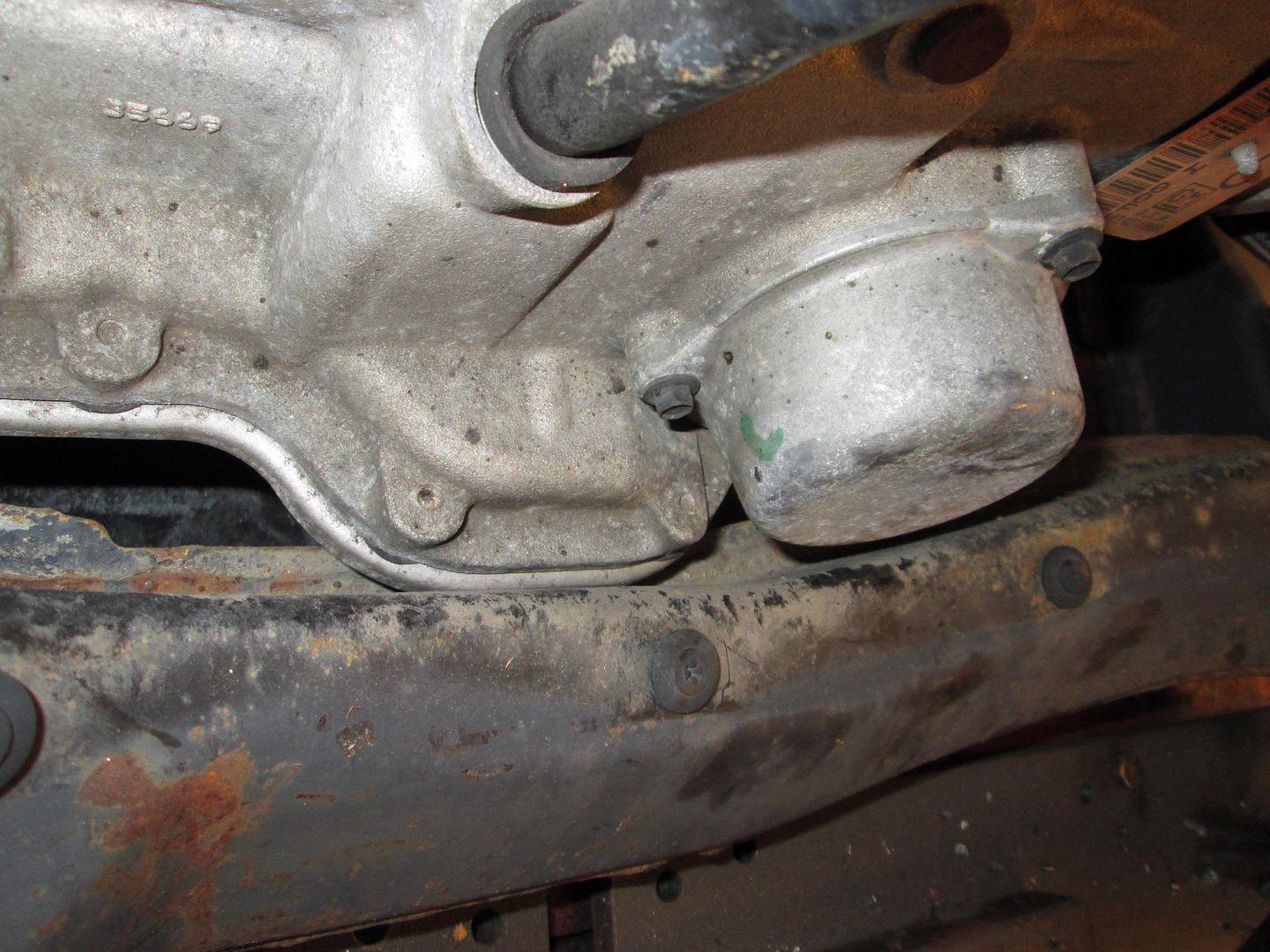
The driver side of the cradle hits the tapered portion of the transmission case. Its hard to see, but that cradle side rail is tapered for the majority of its length, but right behind the rear lateral link it stops and becomes a sharp 90. Cutting and welding in a new section of metal to extend the tapered portion will help this area.
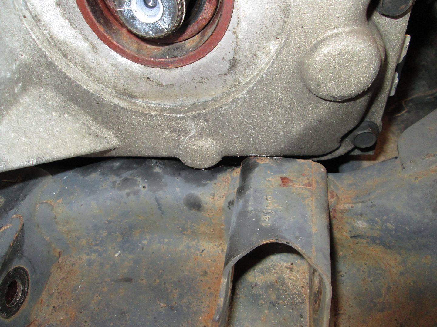
The oil filter is pressed against the oil filter so this area will have to be notched for clearance around the oil filter.
With all the interference issues, the pan of the transmission is still about 1" higher than the bottom of the cradle. My goal is to have it flush with the bottom to maximize room on the topside.
As you can see the front/back placement of the LS4/4T65e-hd only has about 1/2" of available room, so unless you want to do more cradle mods, there isn't much flexibility in the front/back placement.
My wife isn't feeling well today and trying to rest, so I can't proceed with all the cutting/grinding to address the clearance issues at this time.
Since I can't make much noise, I decided to check out clearance options for the using the stock water pump fill location. The idea is that with my decklid hinge box mod it could free up enough room to use the stock LS4 coolant fill which would eliminate the need for any aluminum welding!
The LS4/F40 in my daily driver has this decklid hinge mod and its engine is flush with the bottom of the 88 cradle, so I should be able to do some visual comparisons of the available room.
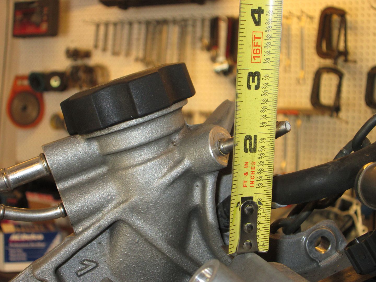
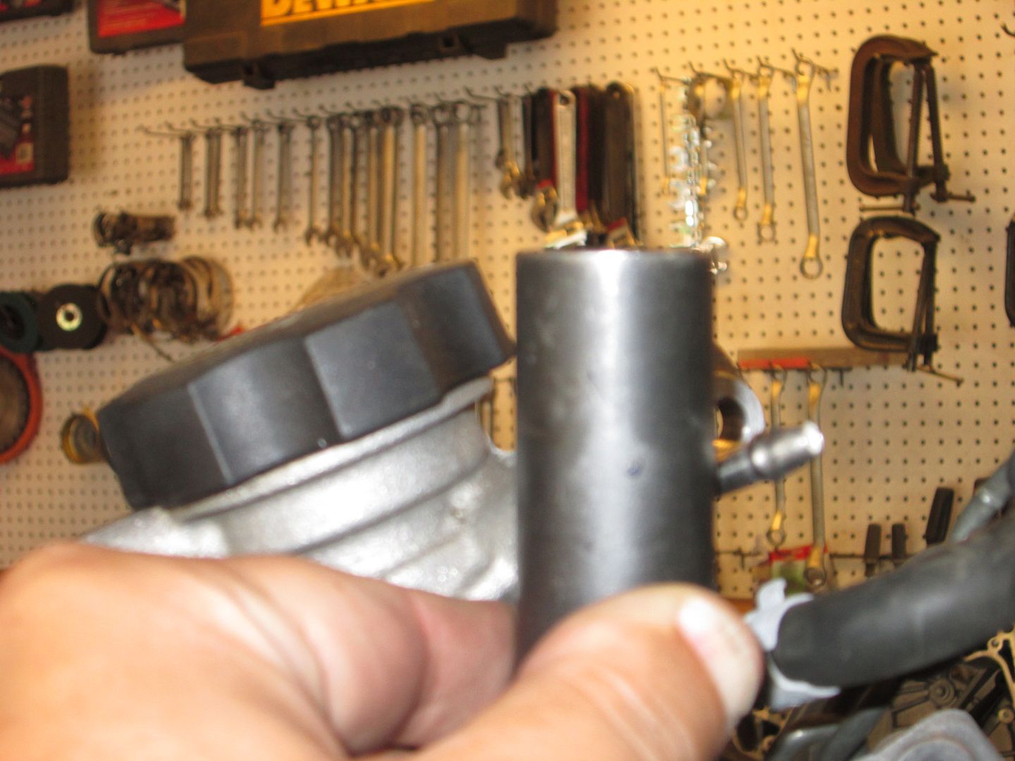
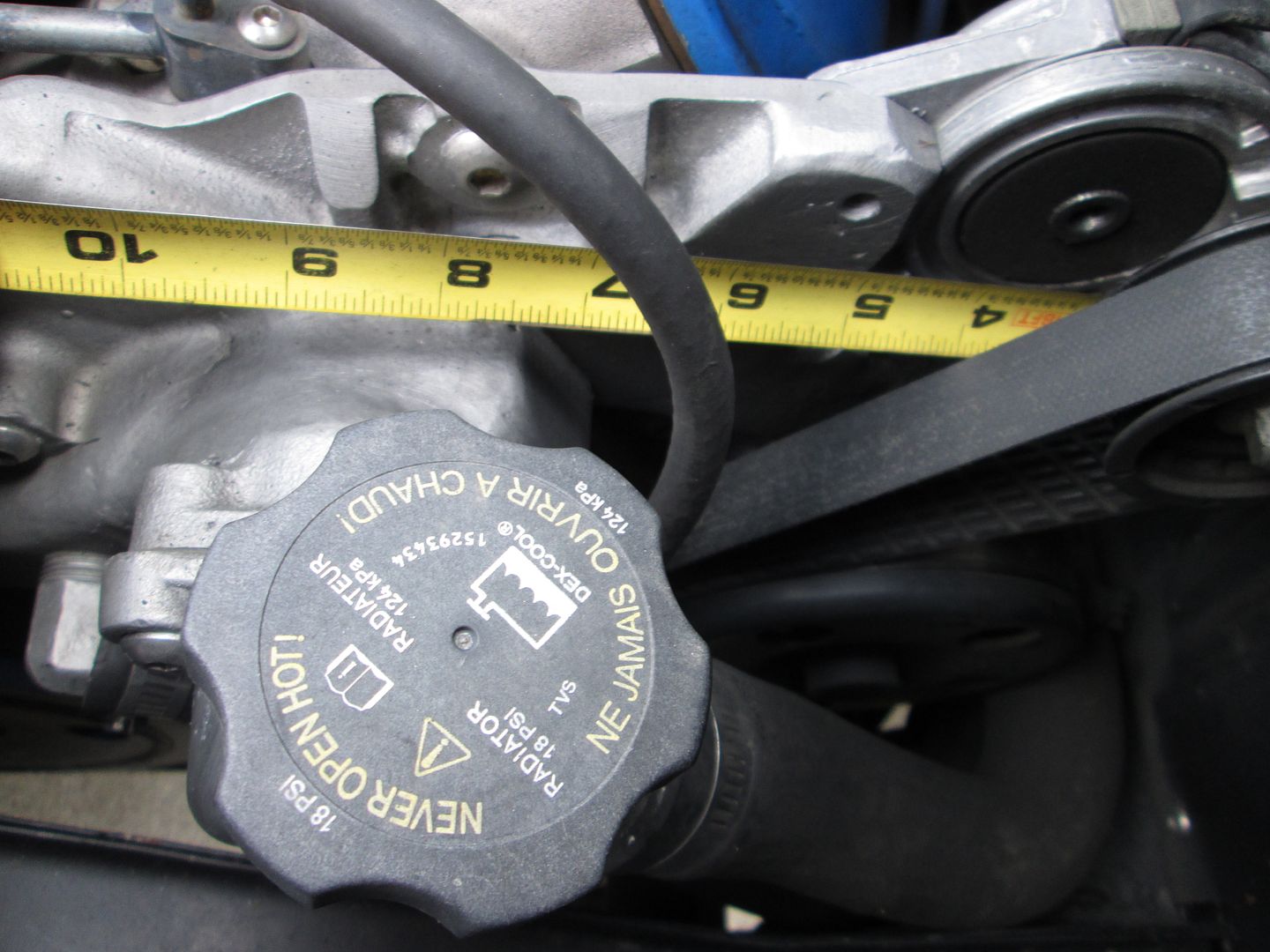
First I started with a tape measure and from the rounded top edge of the valve cover the cap protrudes about 3" at its highest point (mounts at an angle):
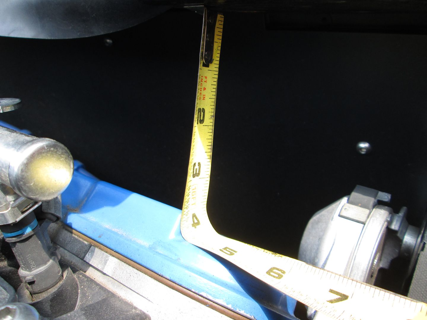
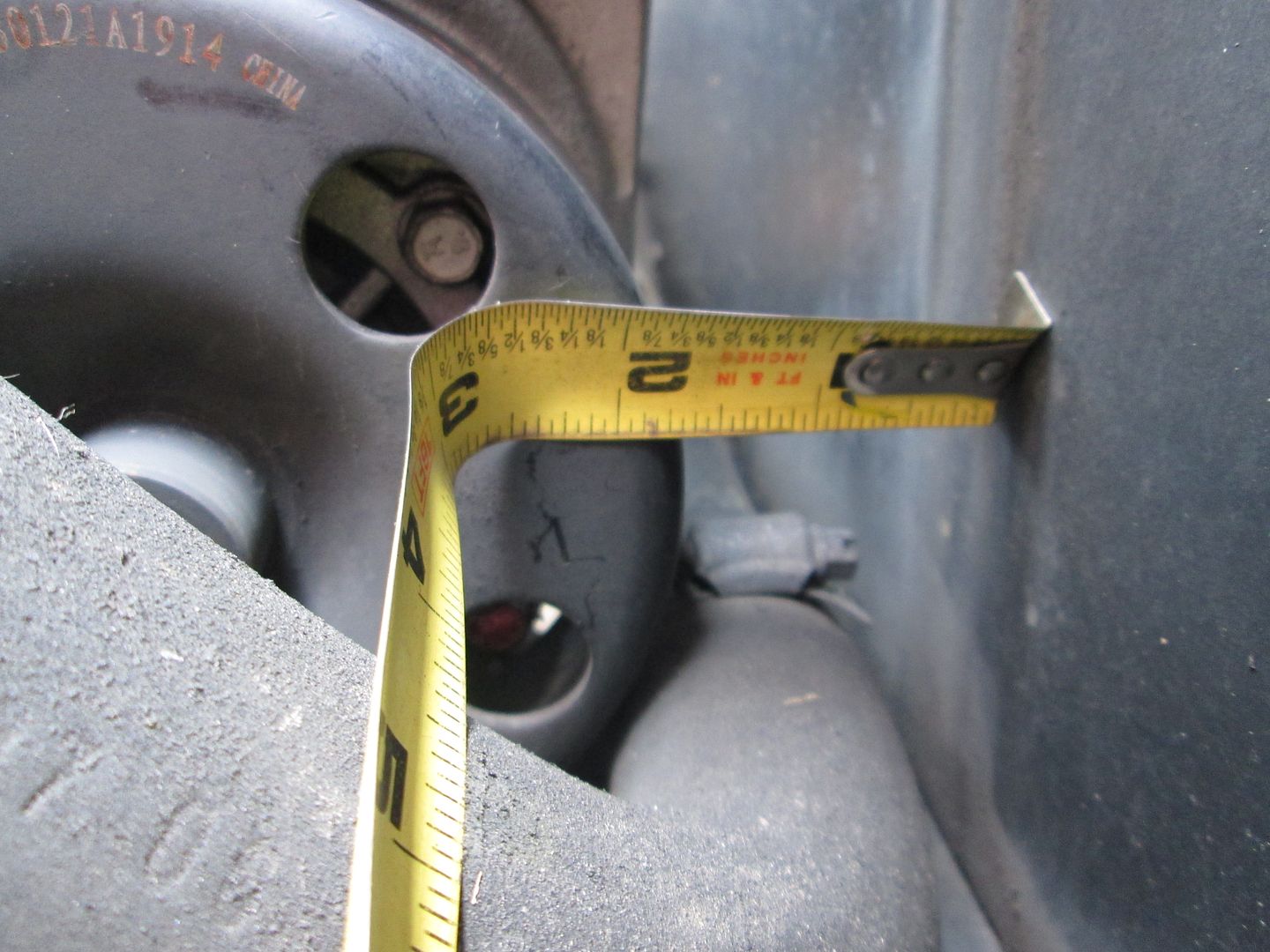
So then I went and measured my car and it has about 4" of room to the bottom of the hinge plate:
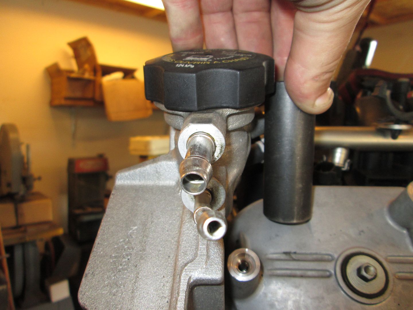
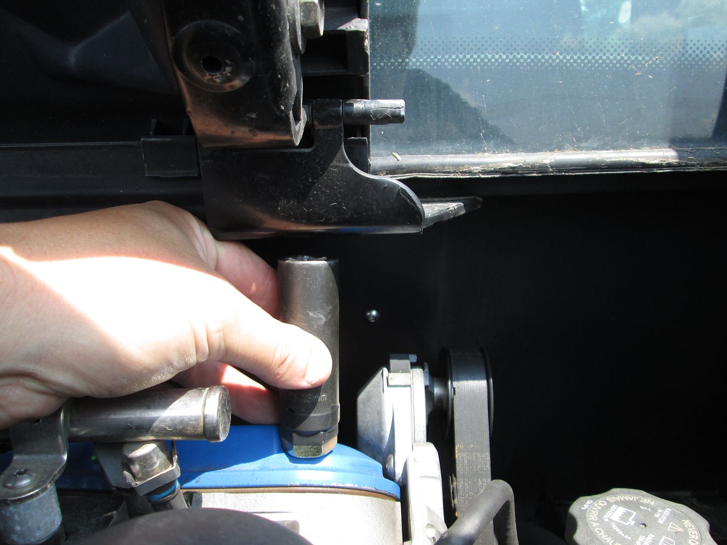
The next step was to "see" where the edge of the hinge will be. So I found a socket that was the right diameter to rest against the lip on the valve cover and the edge of the cap:
Then back to the car to check the edge of the socket to the edge of the hinge. The upper portion of the hinge is about even with the edge of the socket, so when I rework the hinges to remove the hinge boxes, I can offset the hinge plate to the other side to free up vertical clearance above the water pump fill point.
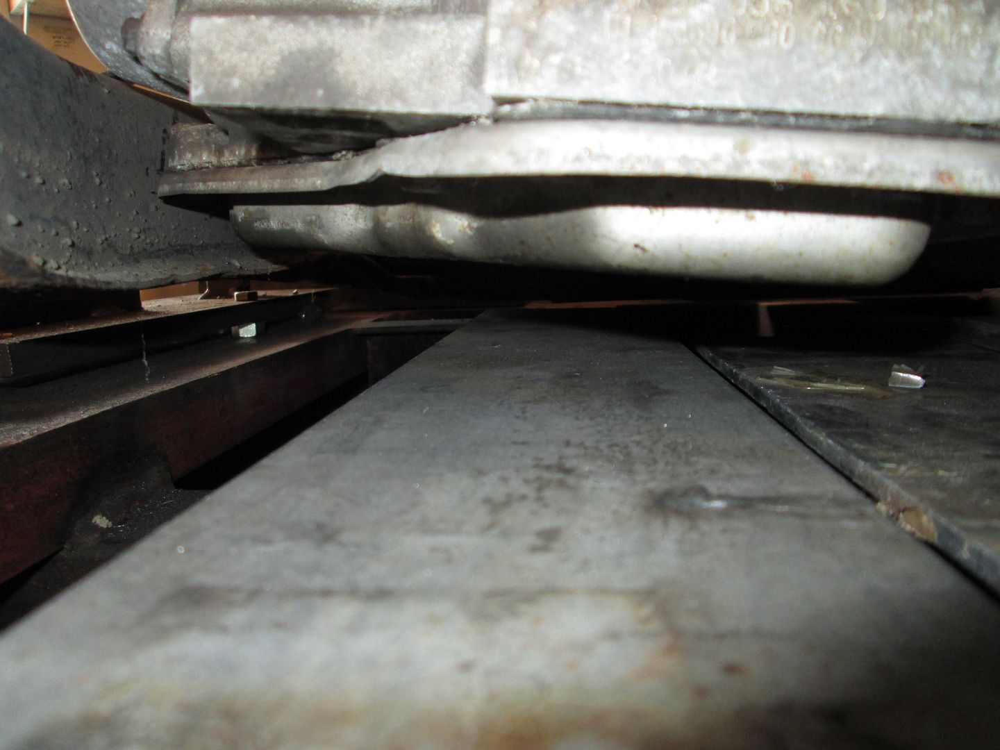
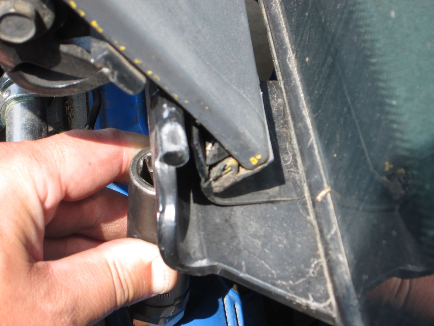
Now I wanted to see if the fill would be blocked by the back glass. So using the socket to get a side shot profile:
Similar view at the car... from the looks of this it might be partially under the rear glass, but I need to check the front/rear placement of my LS4/F40 and the range of placement (only 1/2" of the LS4/4T65e-hd) to see if it helps, makes it worse or doesn't matter.
Rickady88GT was able to keep the stock fill point by relocating the decklid hinge boxes to the side, so I am pretty sure the use of my hinge mod will work as well.
The big unknown is engine placement side to side. If it goes further to the PS, then there is more room for the coolant fill, but then the frame notch for the rear low mount alternator will need to be larger. I would like to minimize any frame notch if possible.
As I move onto the alternator mounting, I will explore both the low rear mount (hidden, but requires frame notch) and top cantilevered mount (no frame notch, but you now see the alternator) options.
Very cool man. Looking forward to the swap and all the key info behind it. Will definitely help down the road for people that want to do this swap. Thanks for keeping our community going strong!
I had very little time tonight, but did check/verify some things...
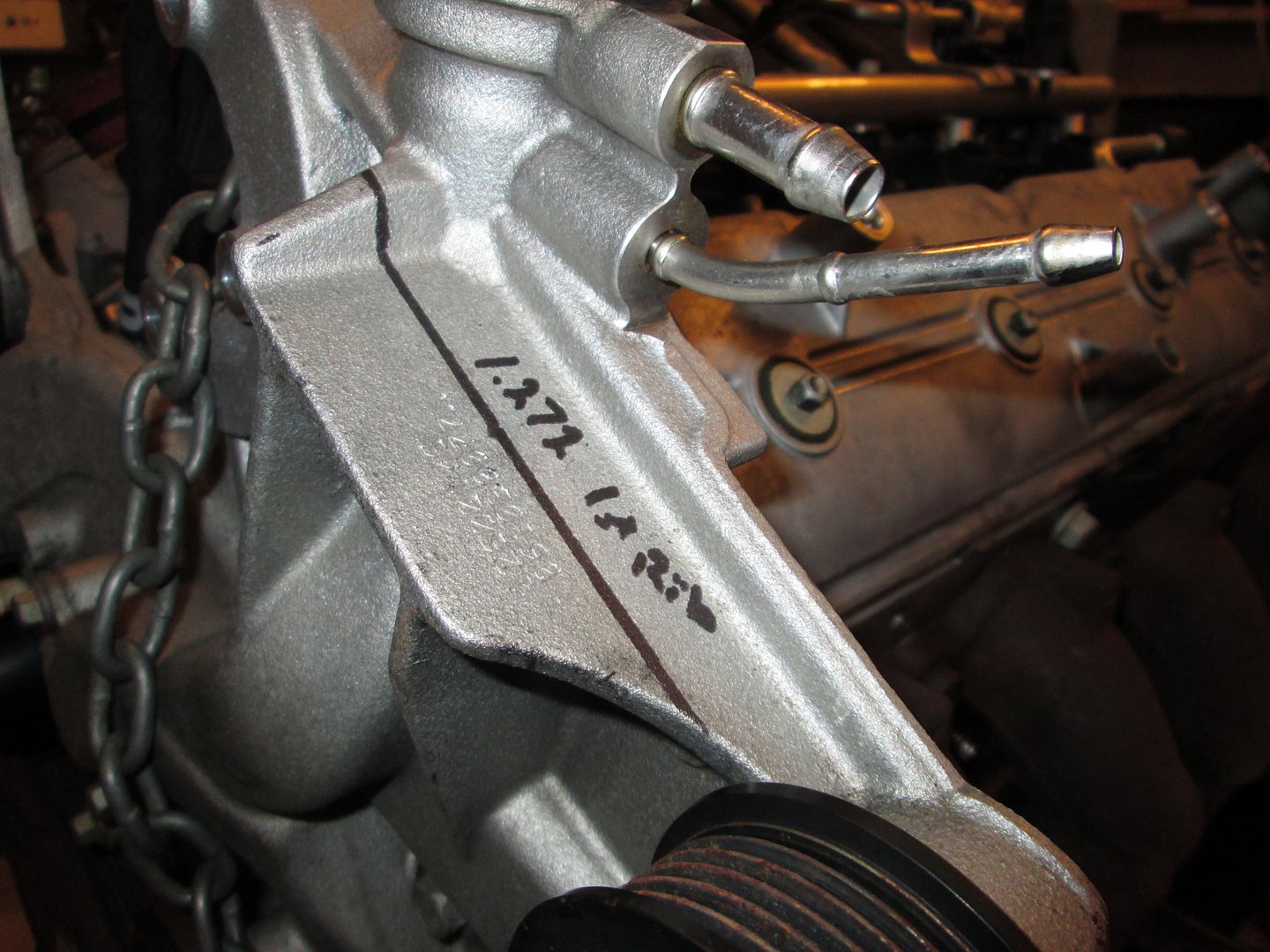
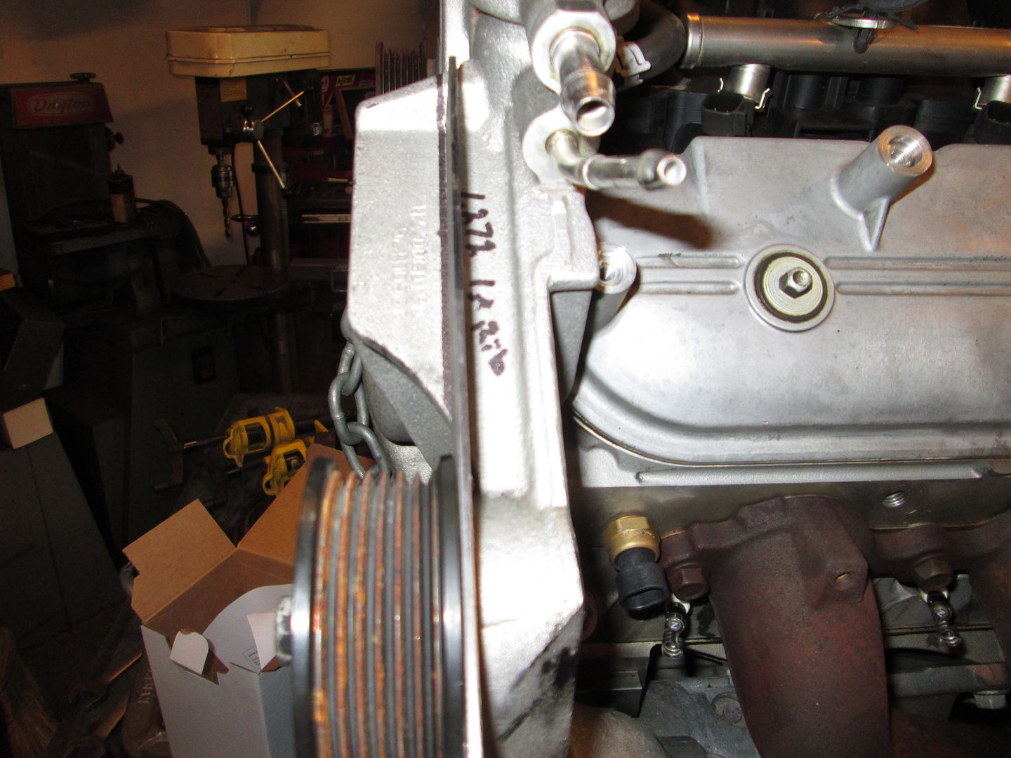
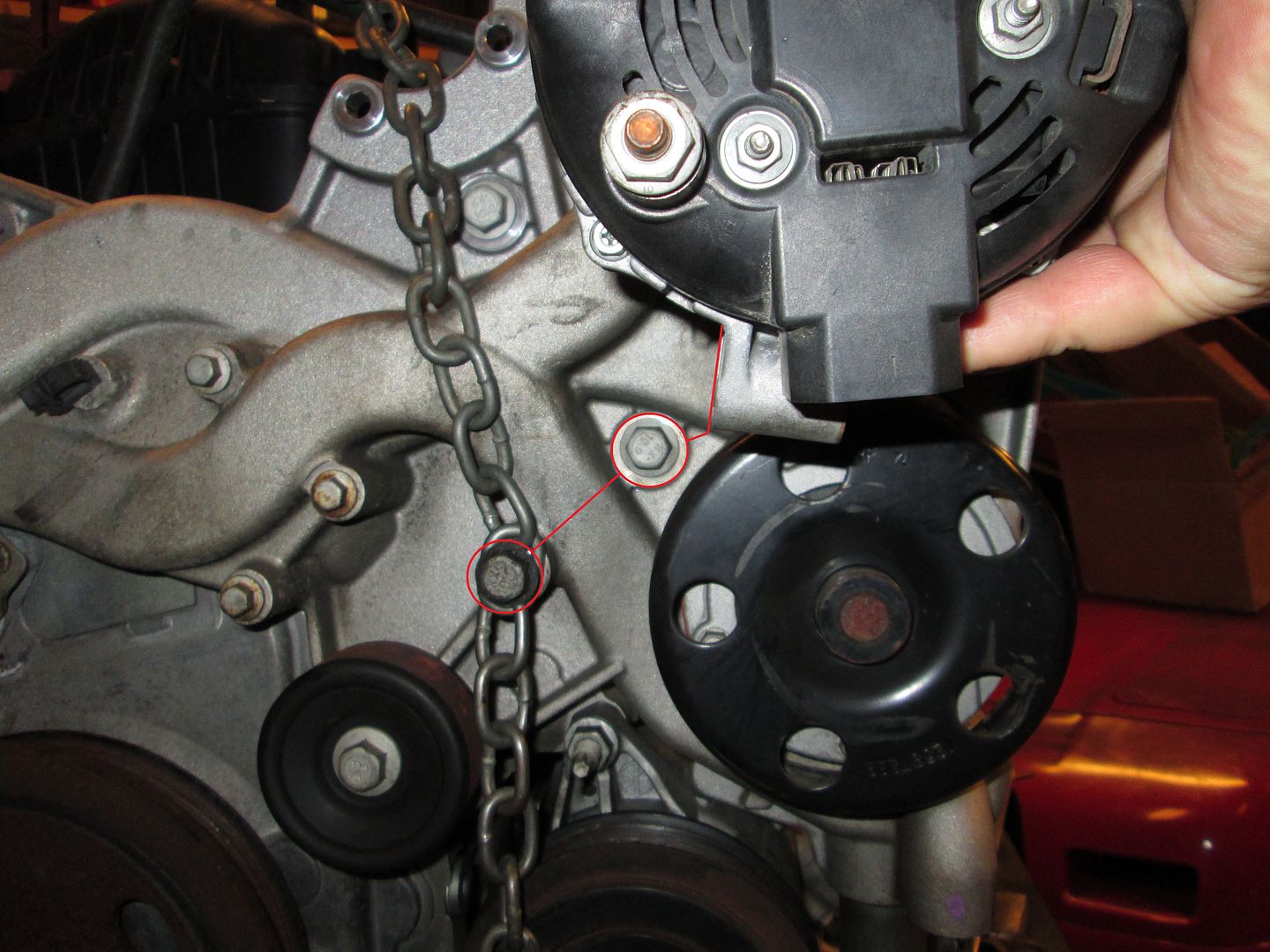
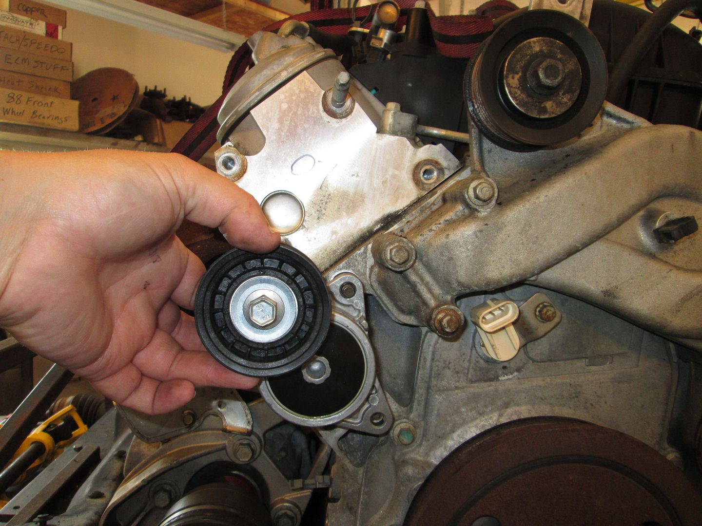
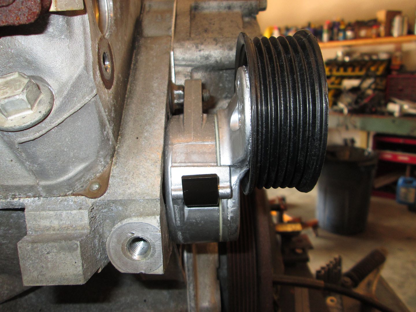
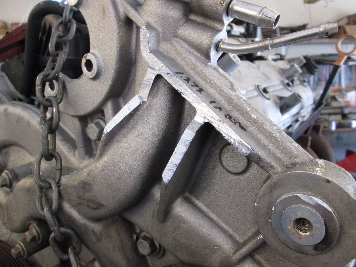
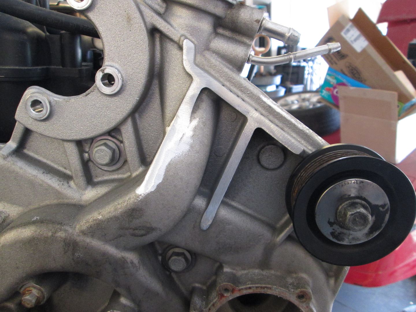
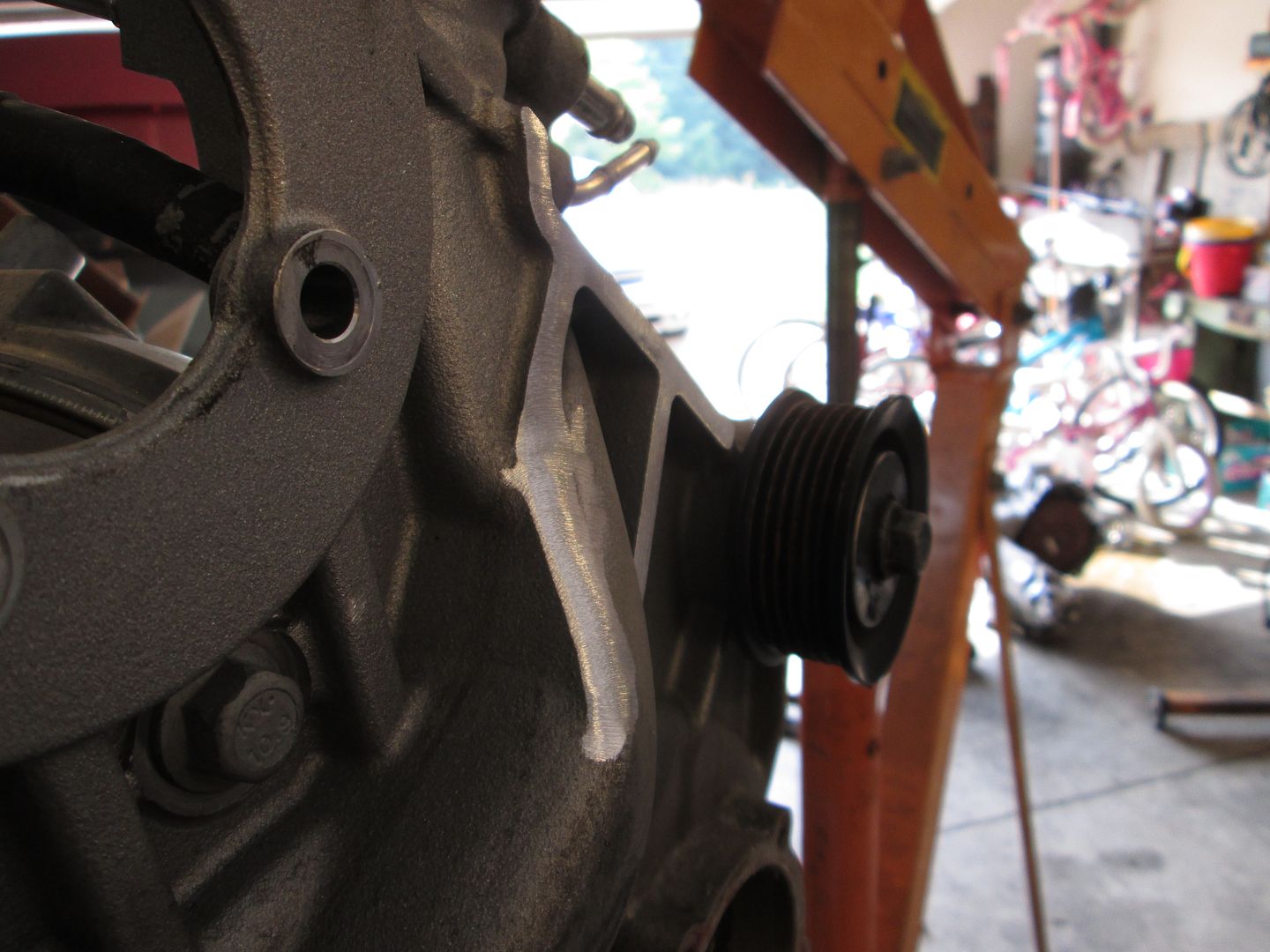
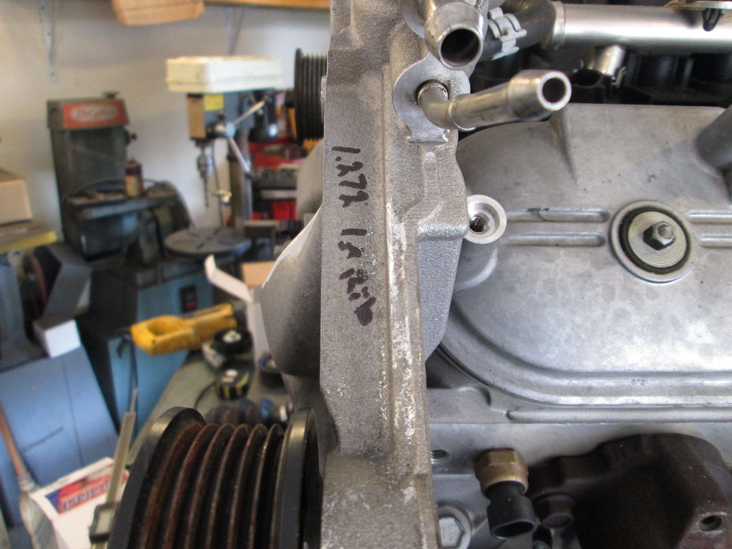
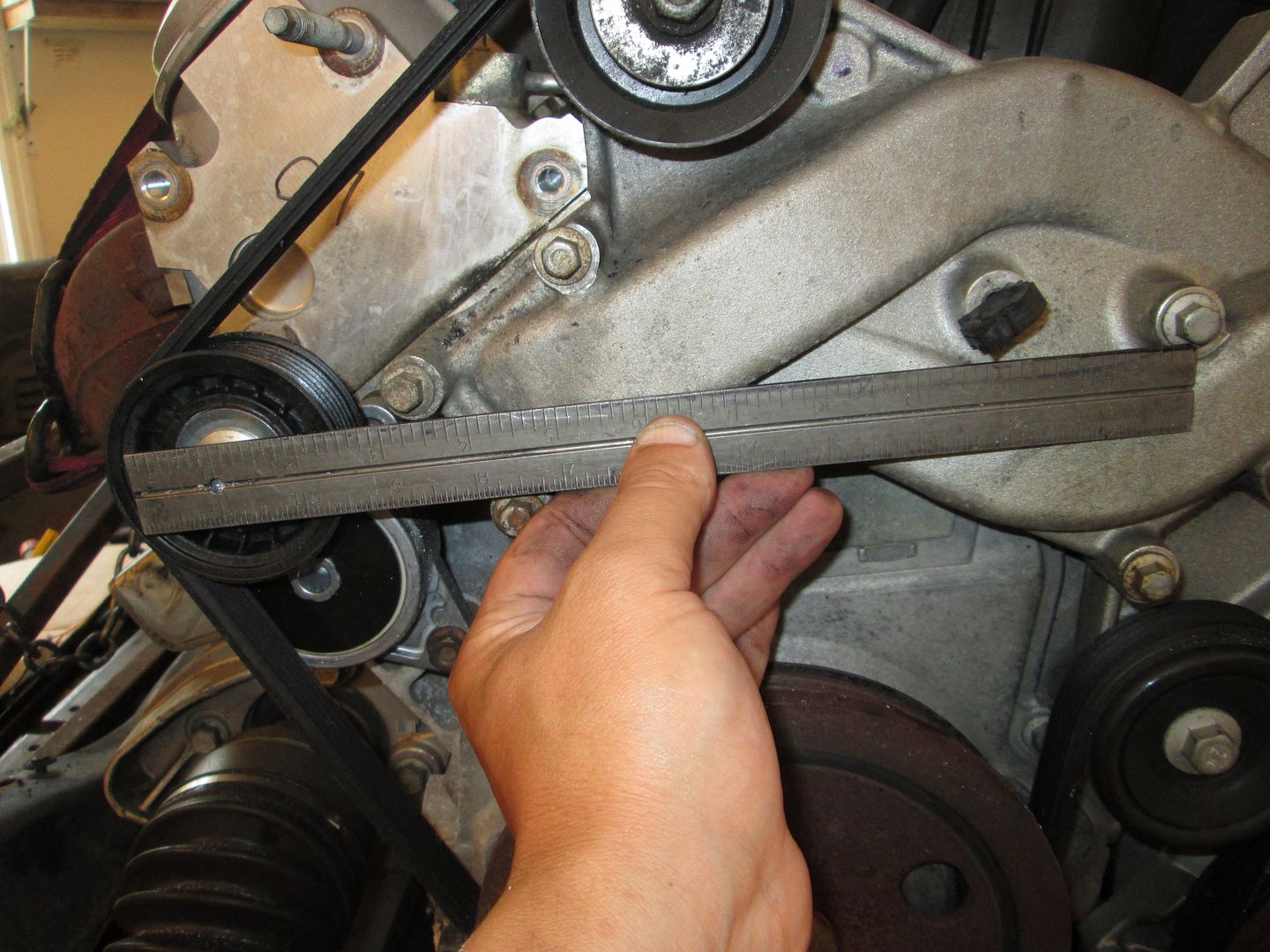
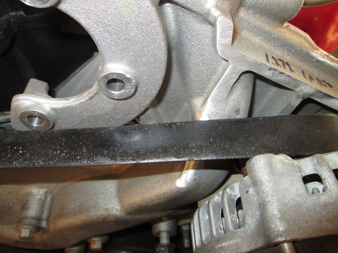
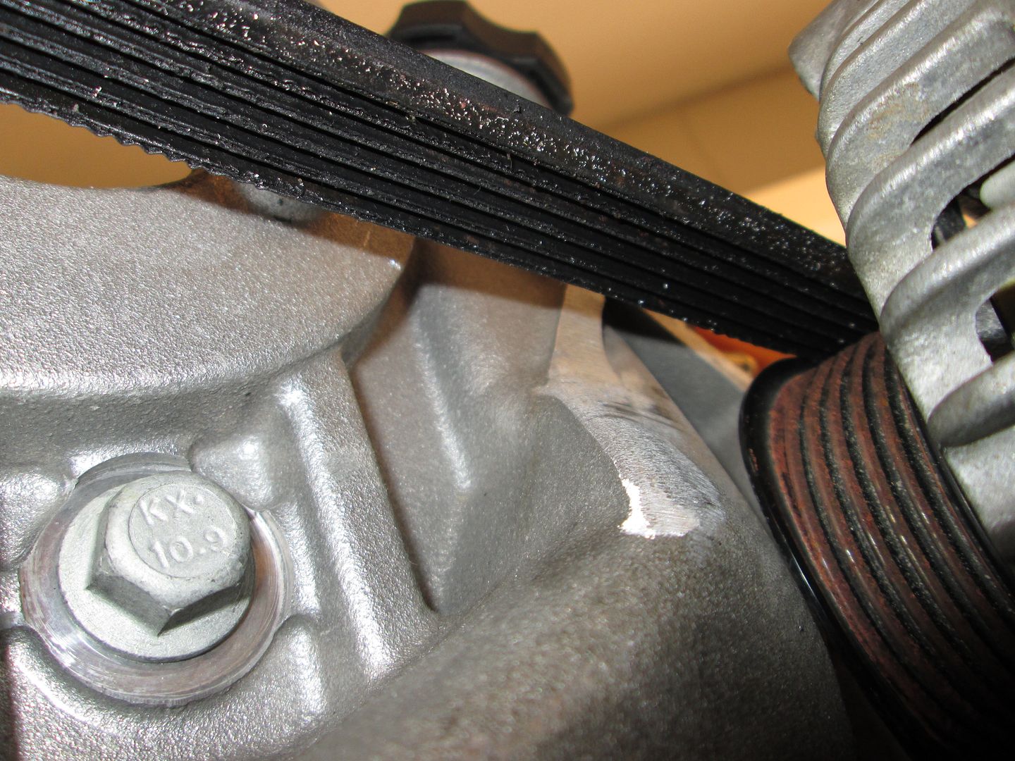
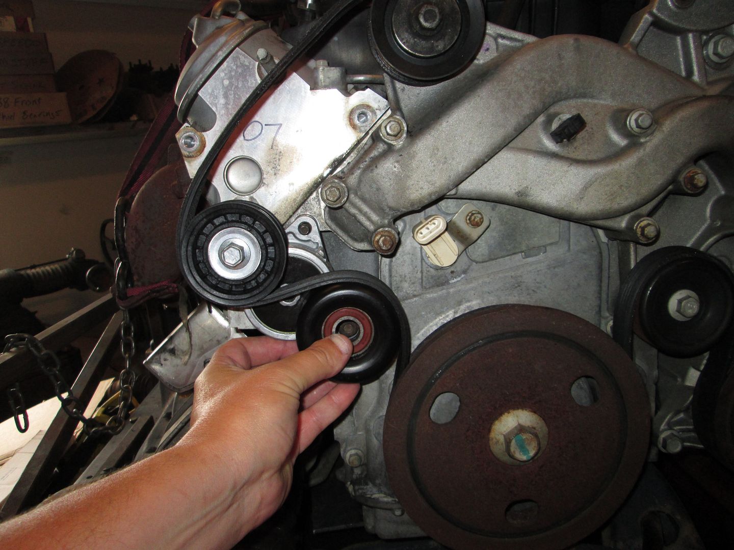
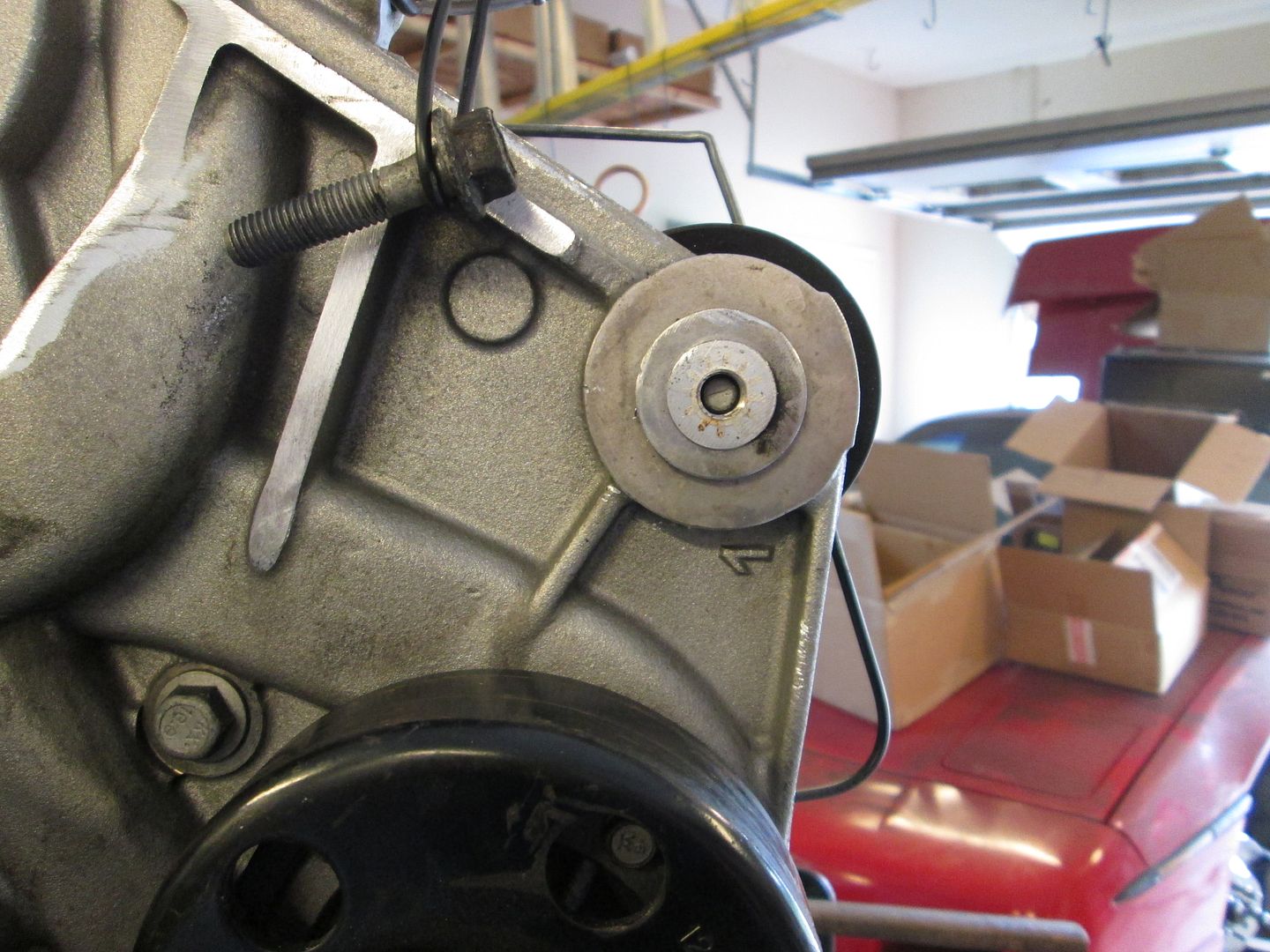
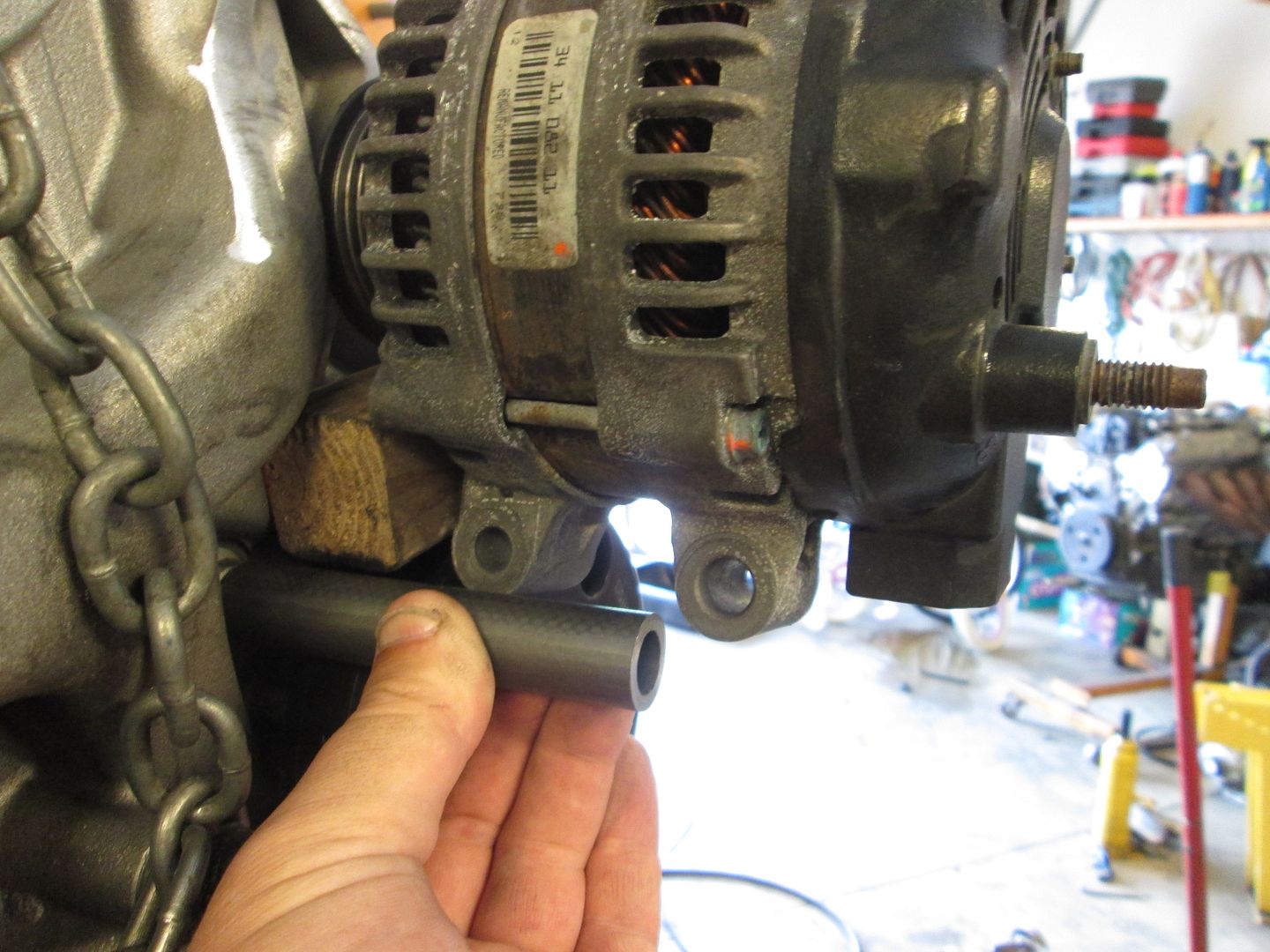
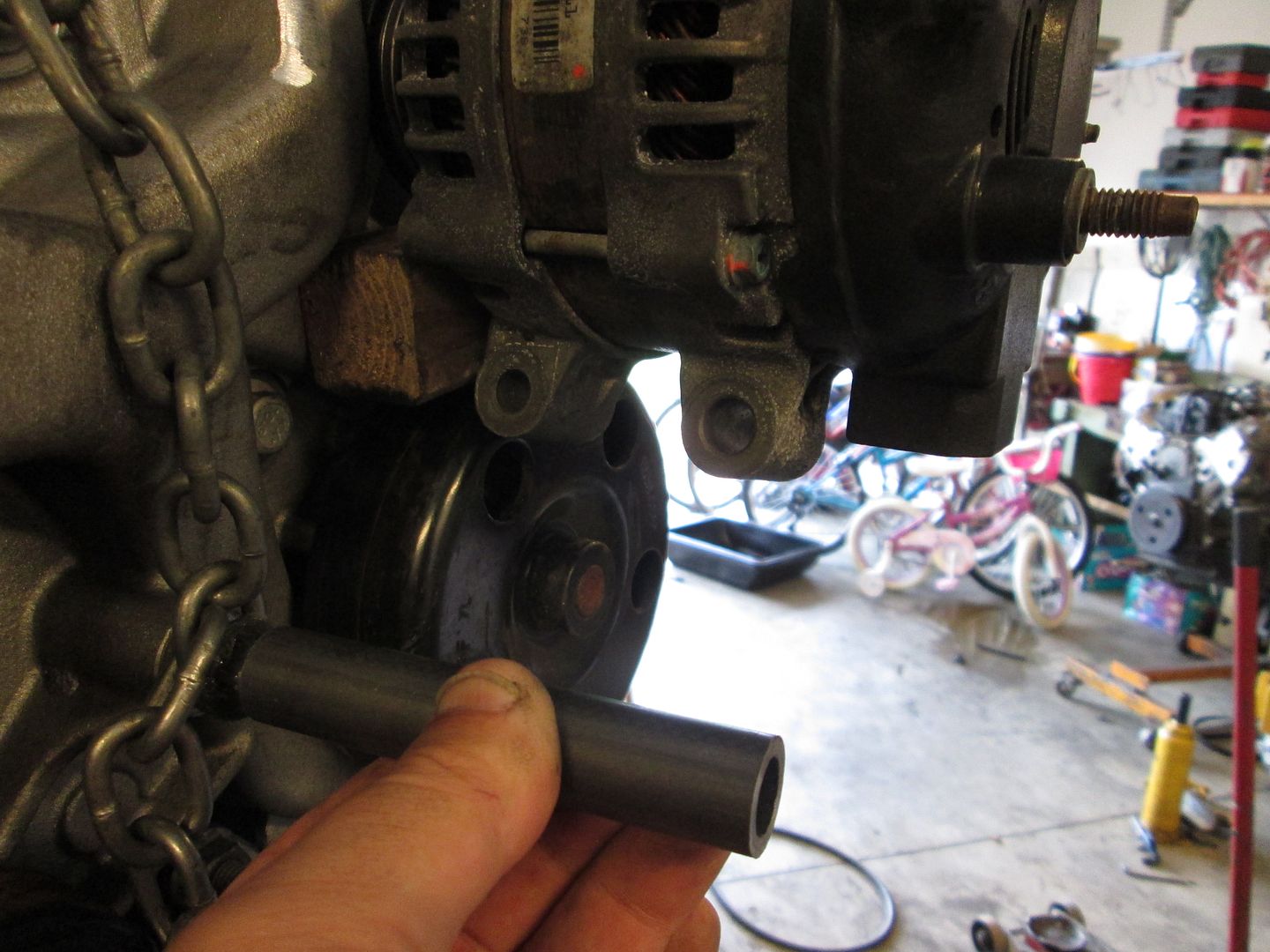
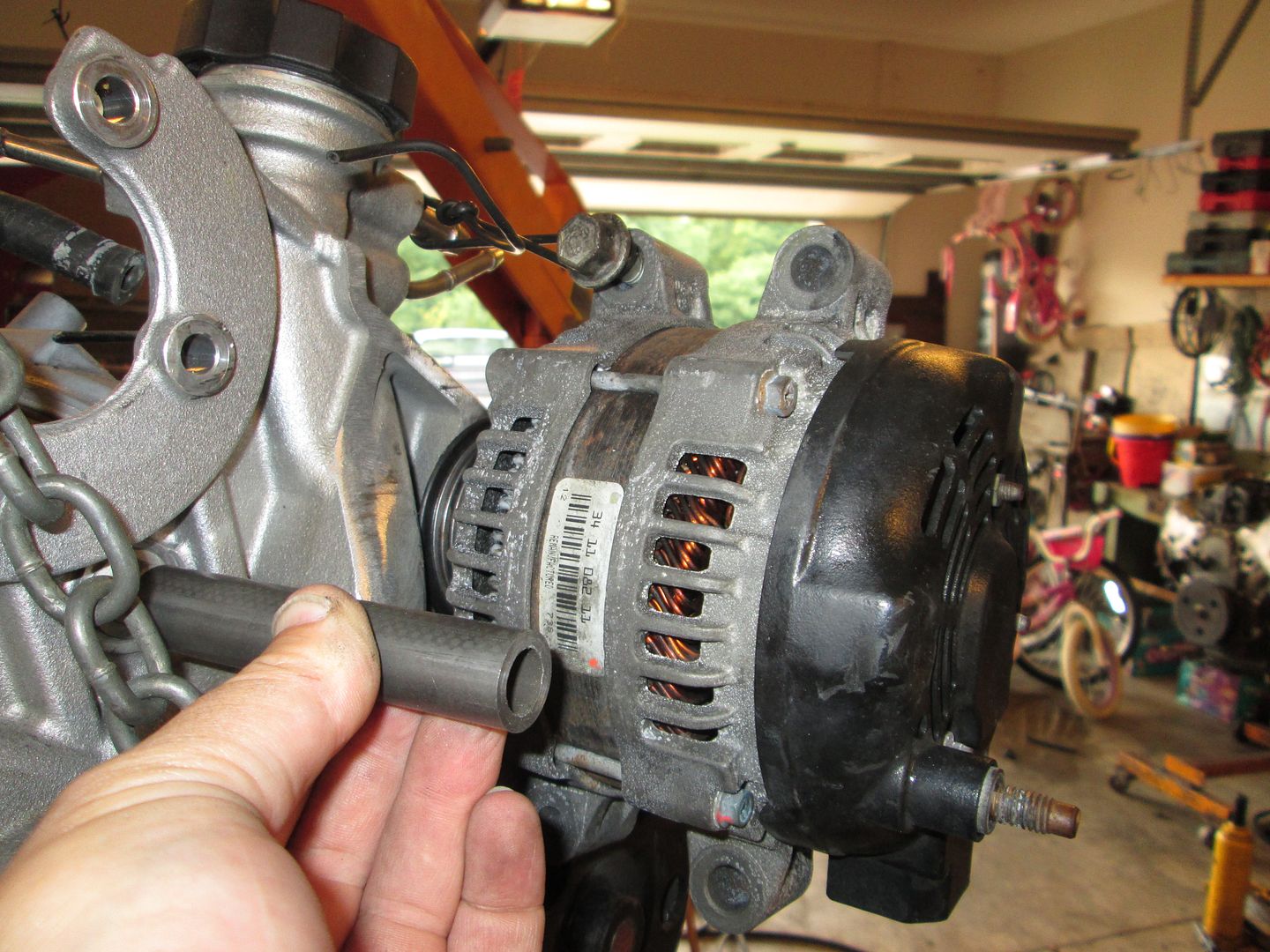
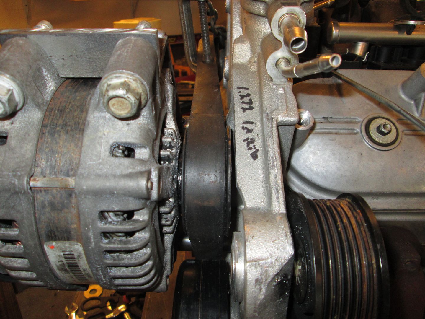
The idler at the top corner of the water pump needs to be relocated no matter what you do with the alternator setup, so this flange will need to be trimmed back some. The black mark is the cut line to make sure it clears the belt and pulley. The # is a measurement to help simplify the pulley alignment in the new location.
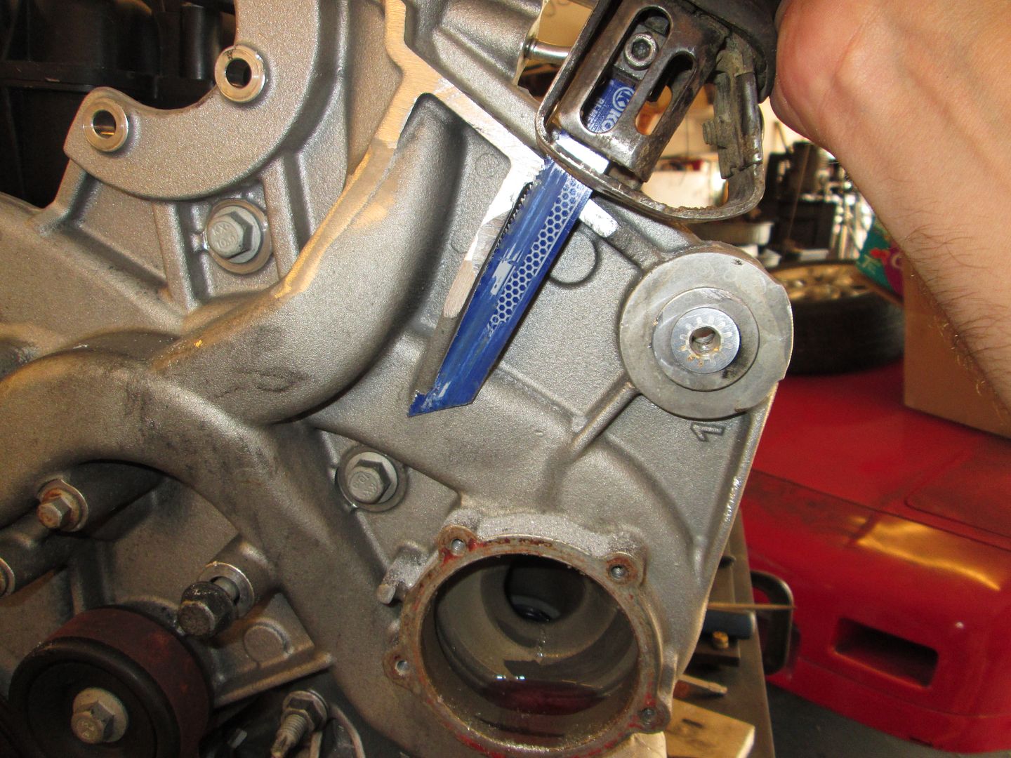
To make the line, I placed a scale tightly behind the pulley and used a sharpie to mark the line. When I cut it I will cut on the engine side of the line, which should leave the thickness of the blade/disk for pulley clearance.
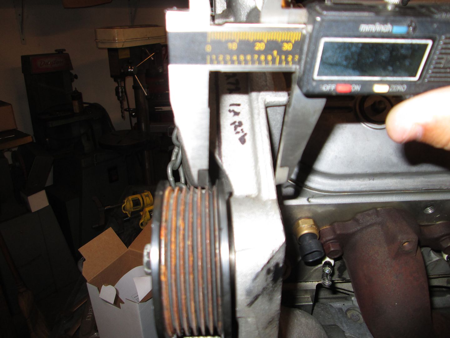
For the measurement I used some digital calipers and measured from the engine side of the pump to the point on the first pulley rib. The back of the pump is cast, but looked very consistent, so its a good place to start. I can verify this and make further tweaks, but this should get it within +/- 1/32 on the very first try.
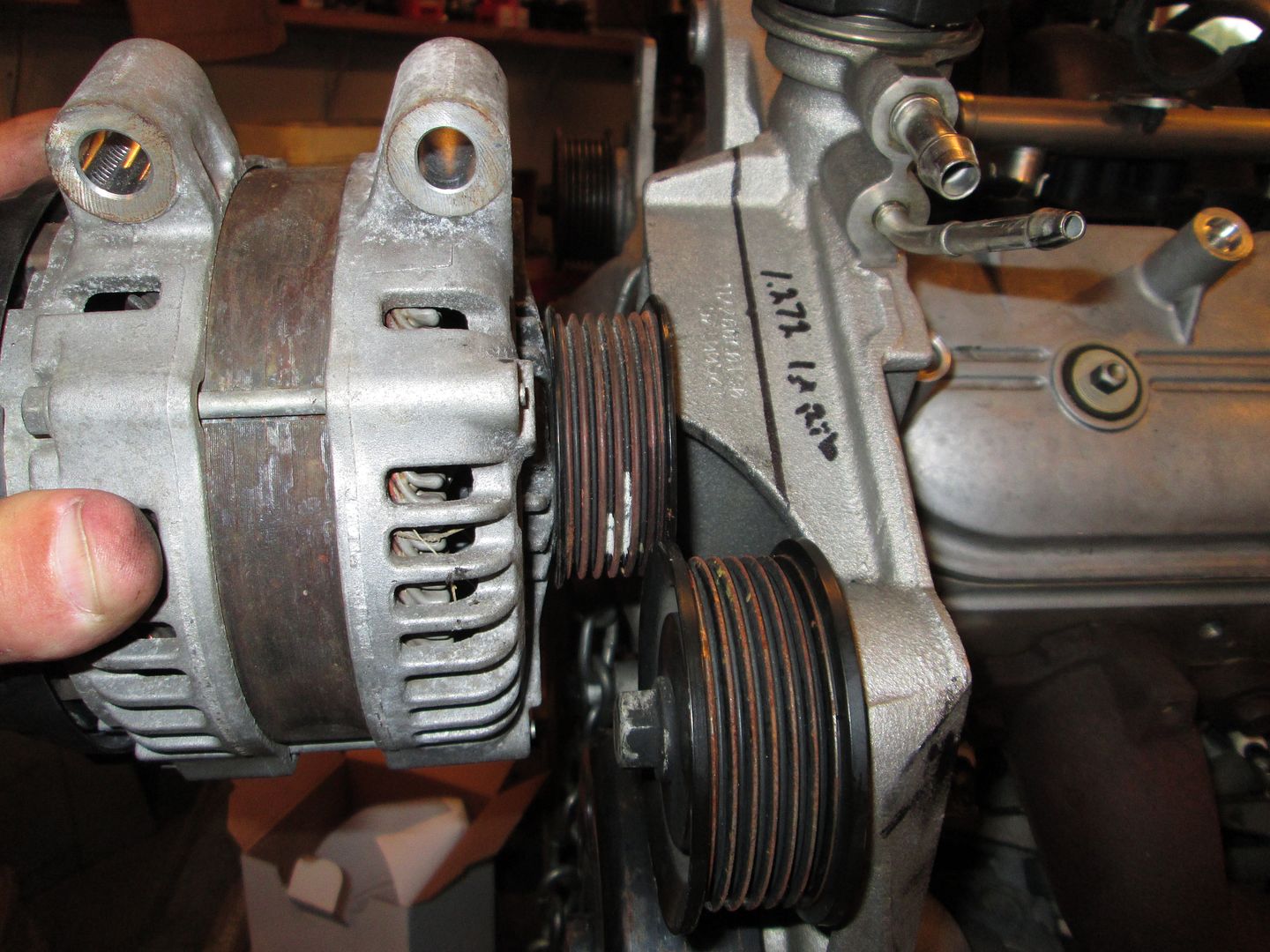
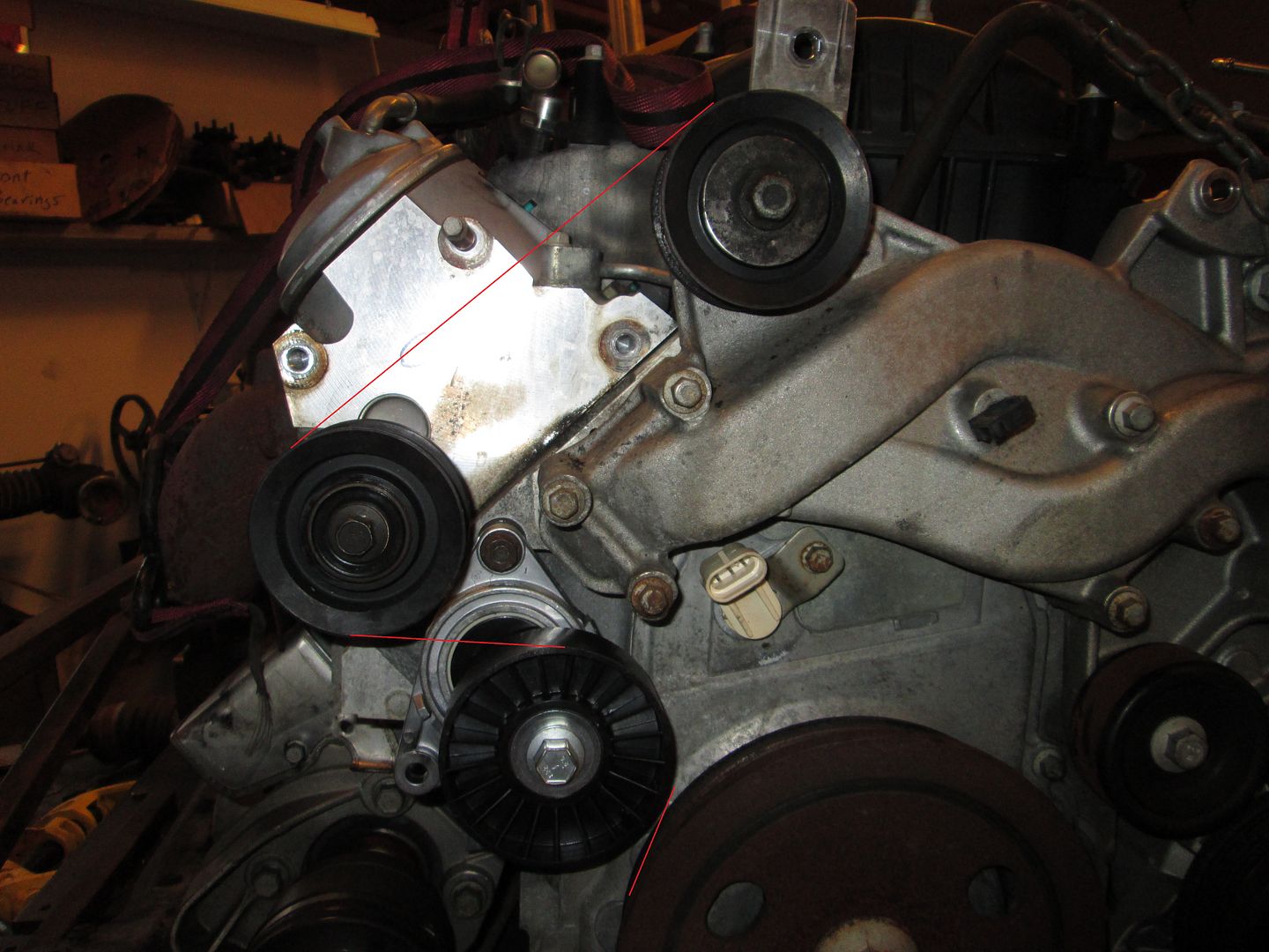
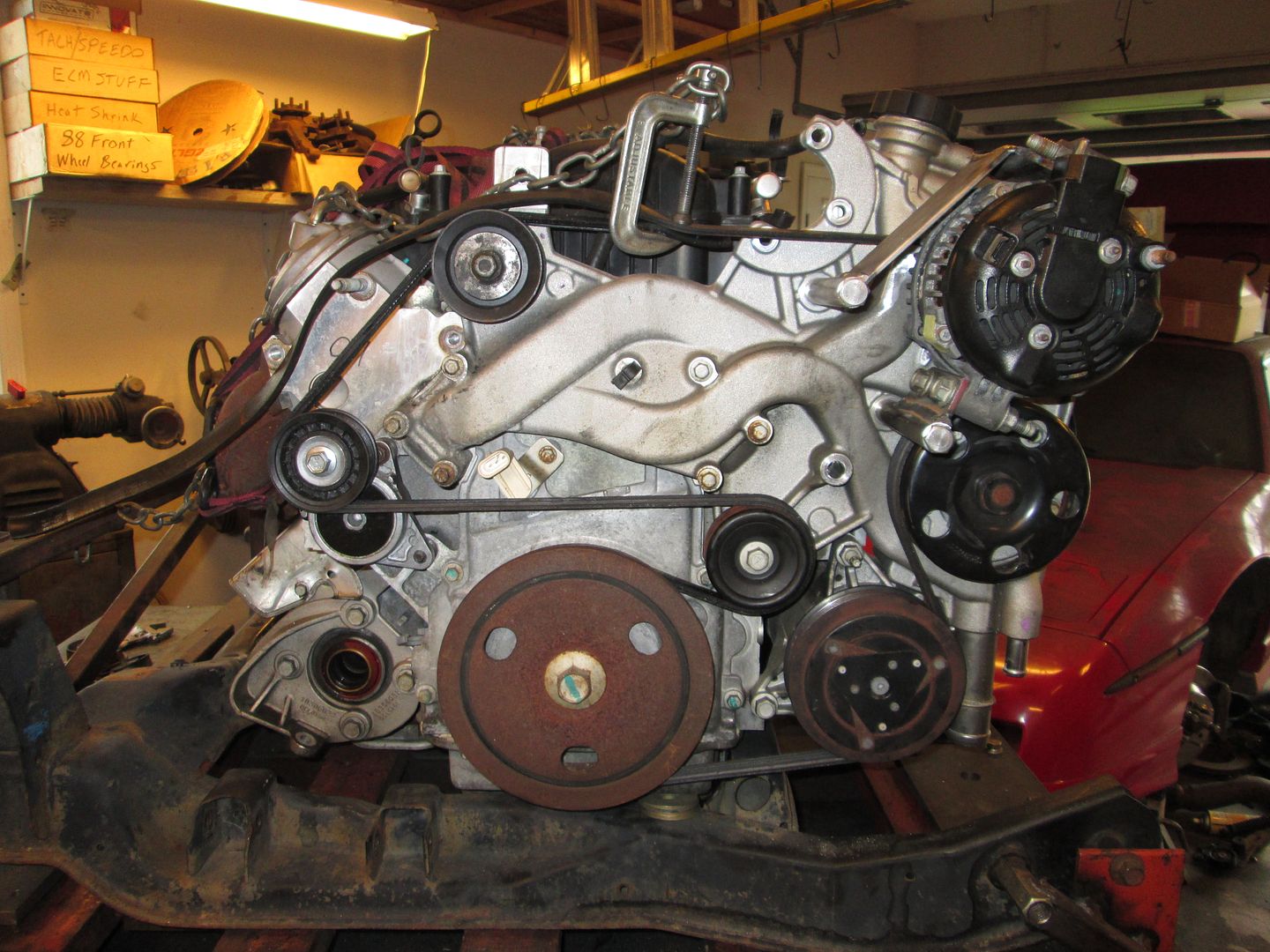
I am planning to make brackets to mount the alternator in a couple of places. One of them is to cantilever it and use the alternator pulley in place of the upper corner pulley by the fill point. Something like this, but with the rib cut out so the alternator could be slid into position. Placement will be critical for the belt to clear the pump and for the alternator to fit under the rear glass.
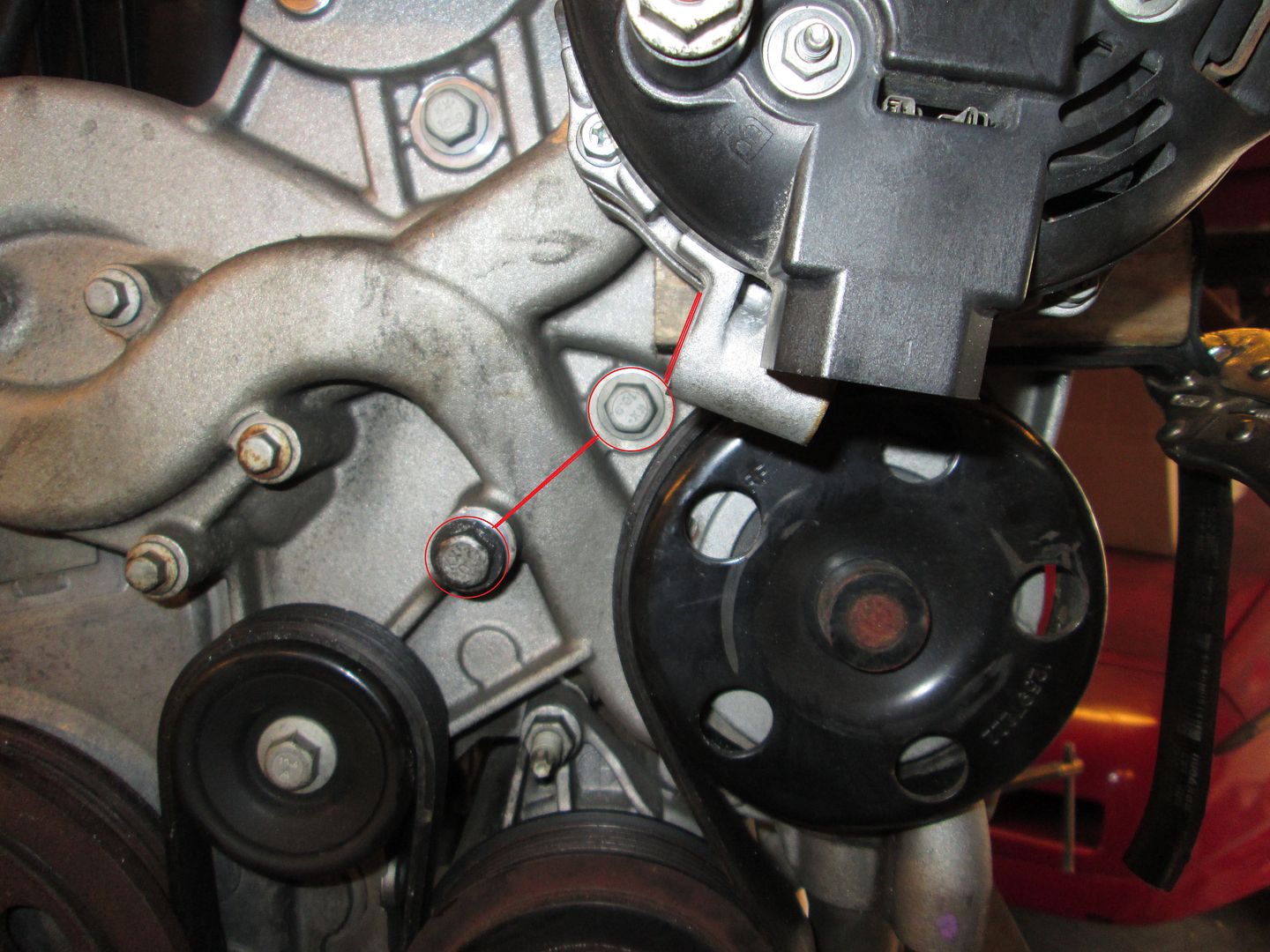
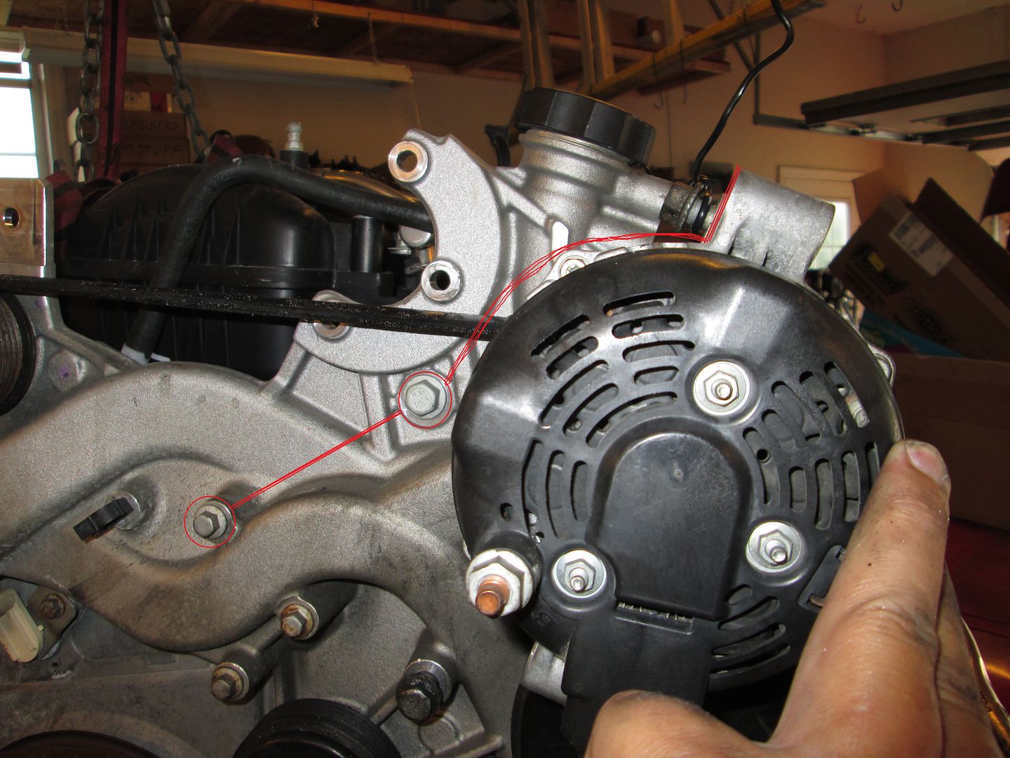
Here is a first thought on the lower mount point. Pick up 2 M12 bolts that go into the head/block and use some longer bolts and some 3/4" OD sleeves with some metal plates welded between them and a metal tab to mount the alternator. Still working on the top side, but there are a few bolt locations to pick from.
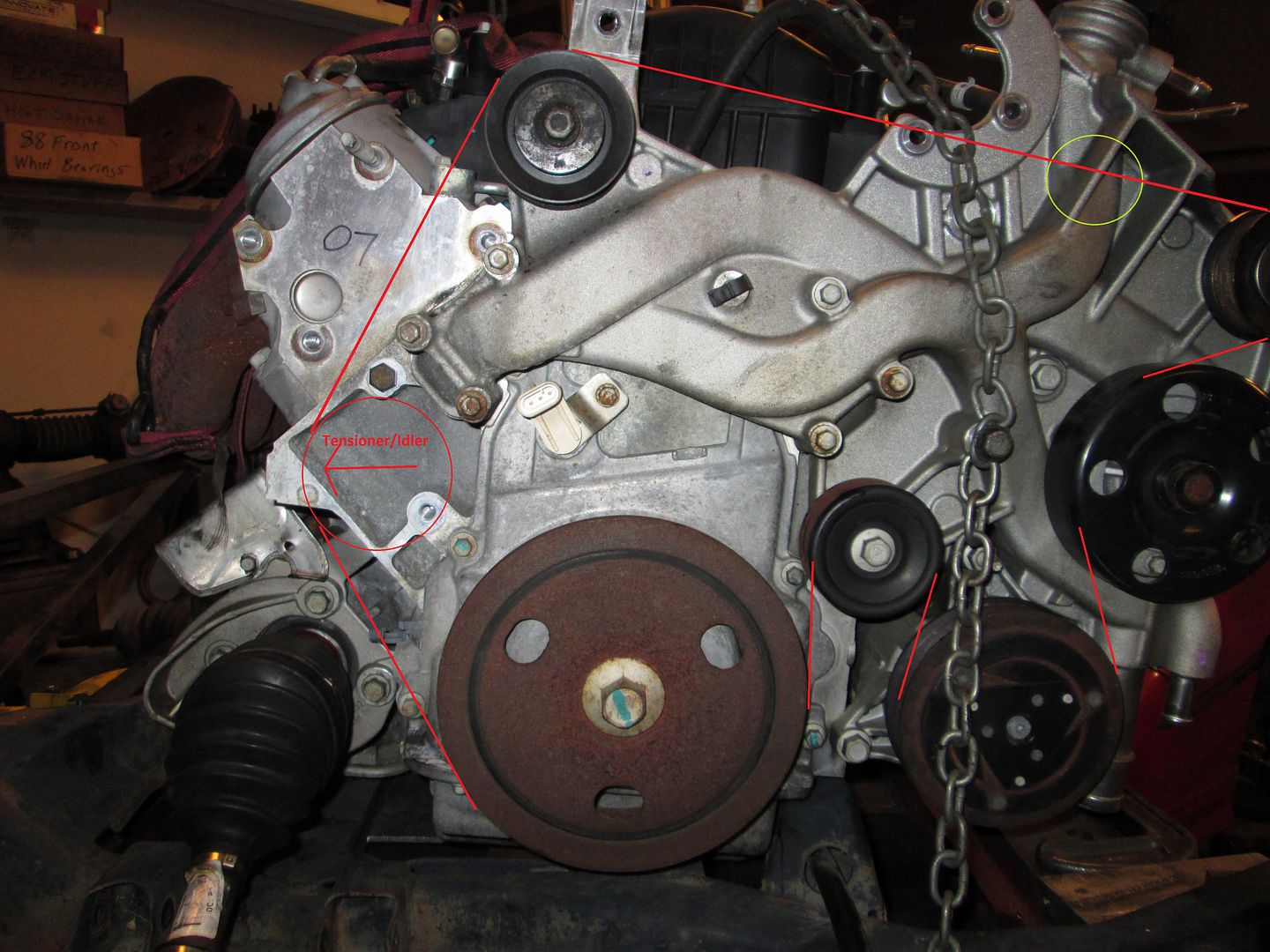
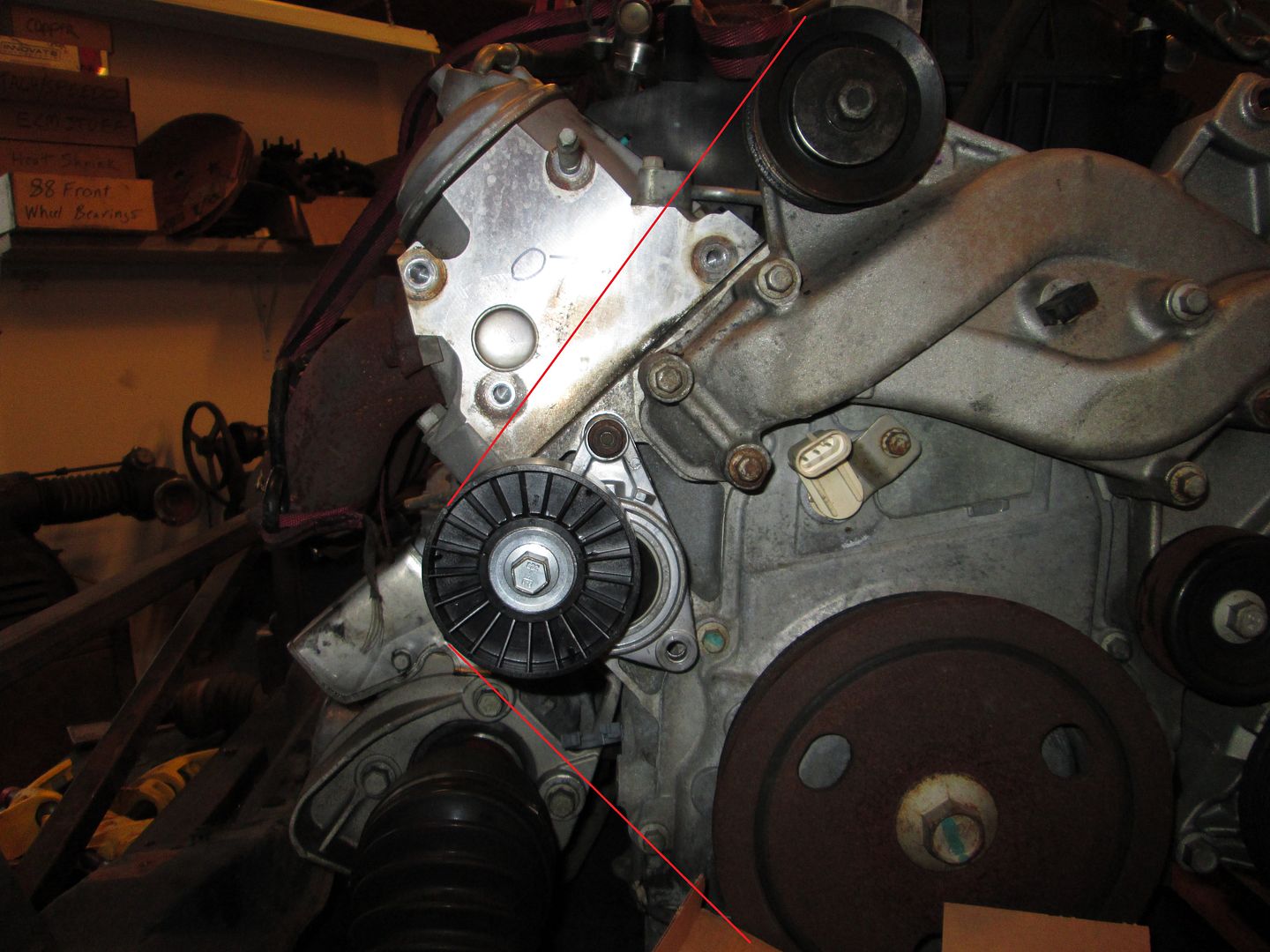
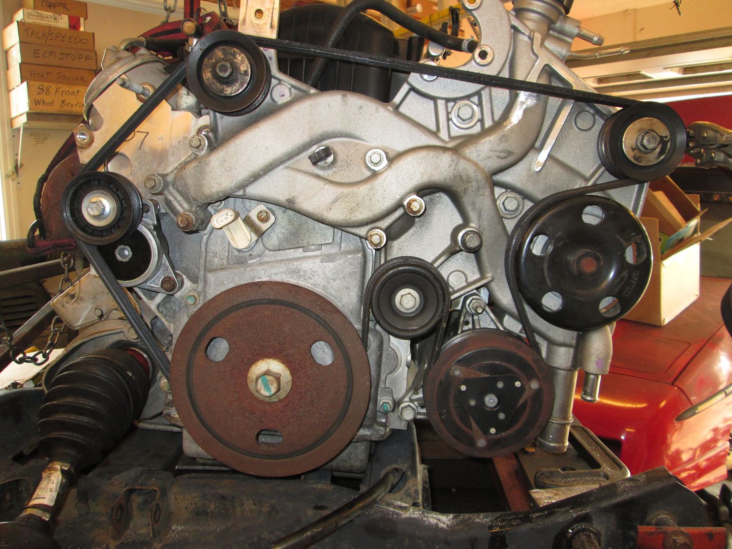
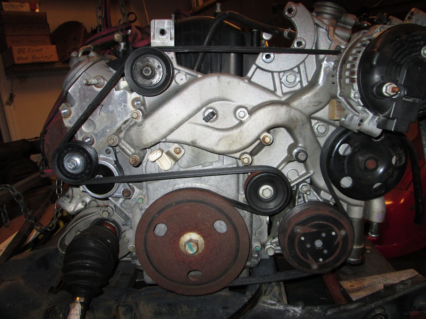
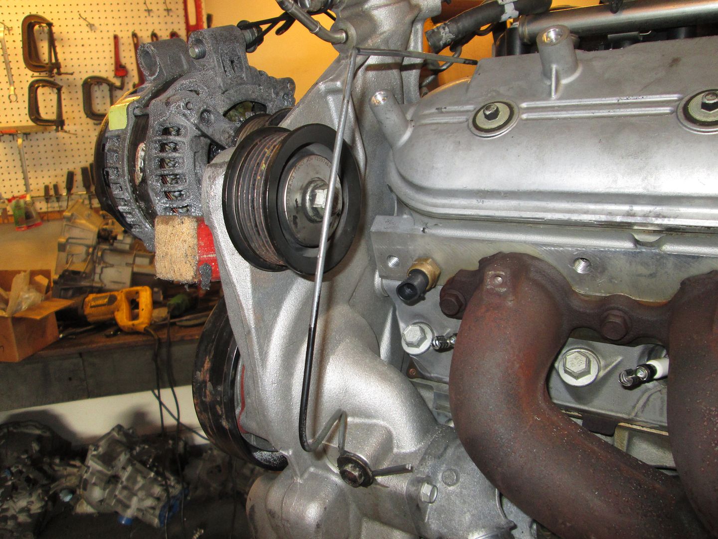
The belt routing for such an alternator location would look something like below. I am hoping I can find a small/compact tensioner that will fit in that spot and push the belt away from the engine. This area is very tight because the strut tower starts encroaching in the engine bay, so the tensioner/ belt path needs to remain as low as possible. This picture also shows a circled area to watch for belt interference with the pump:
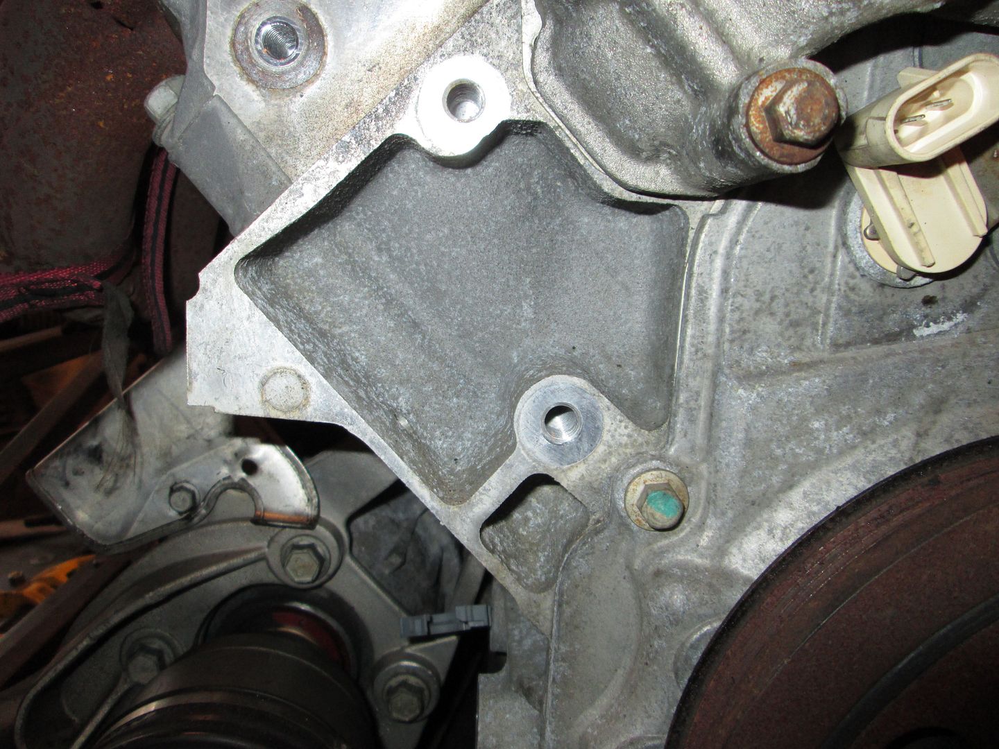
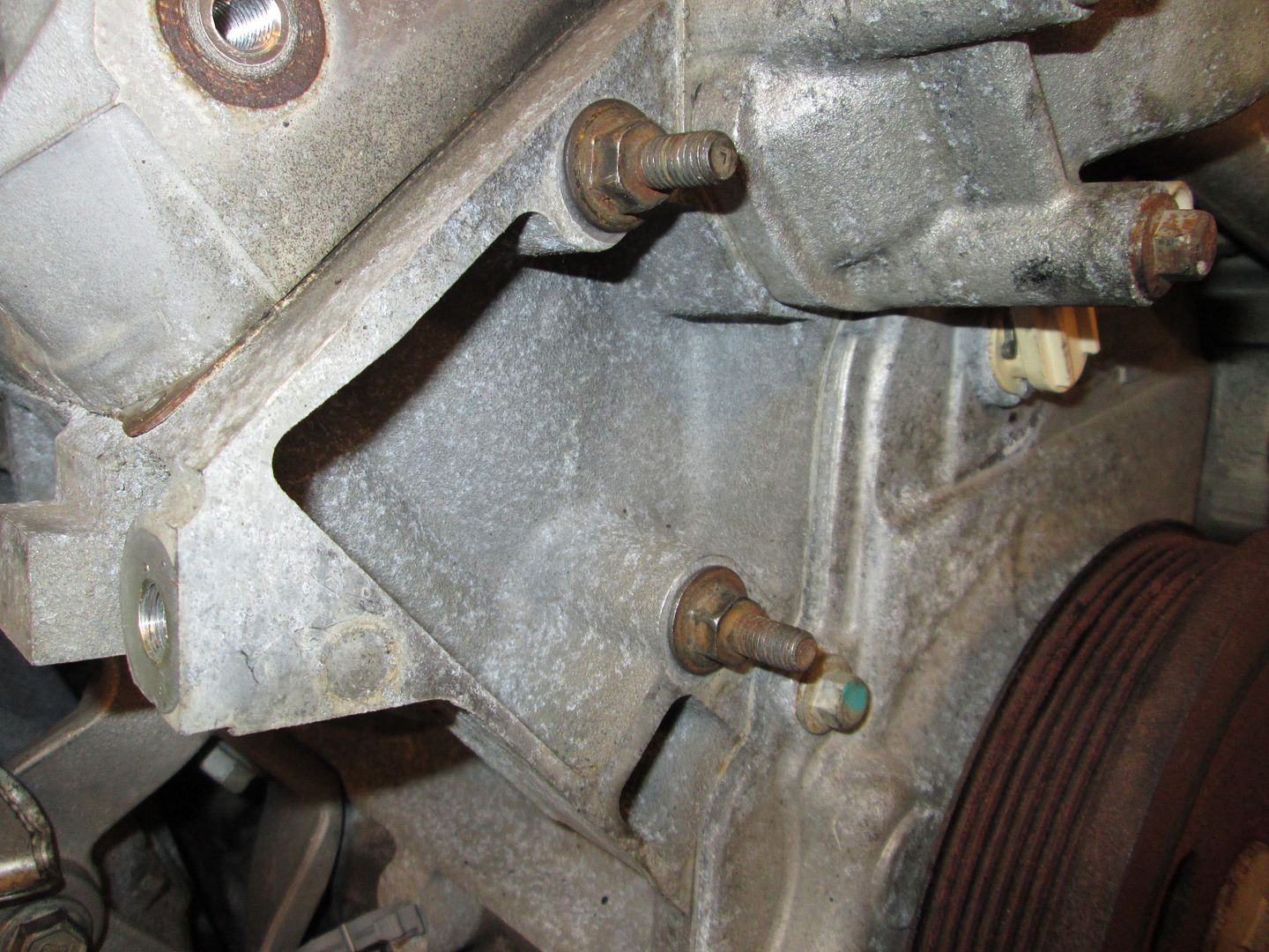
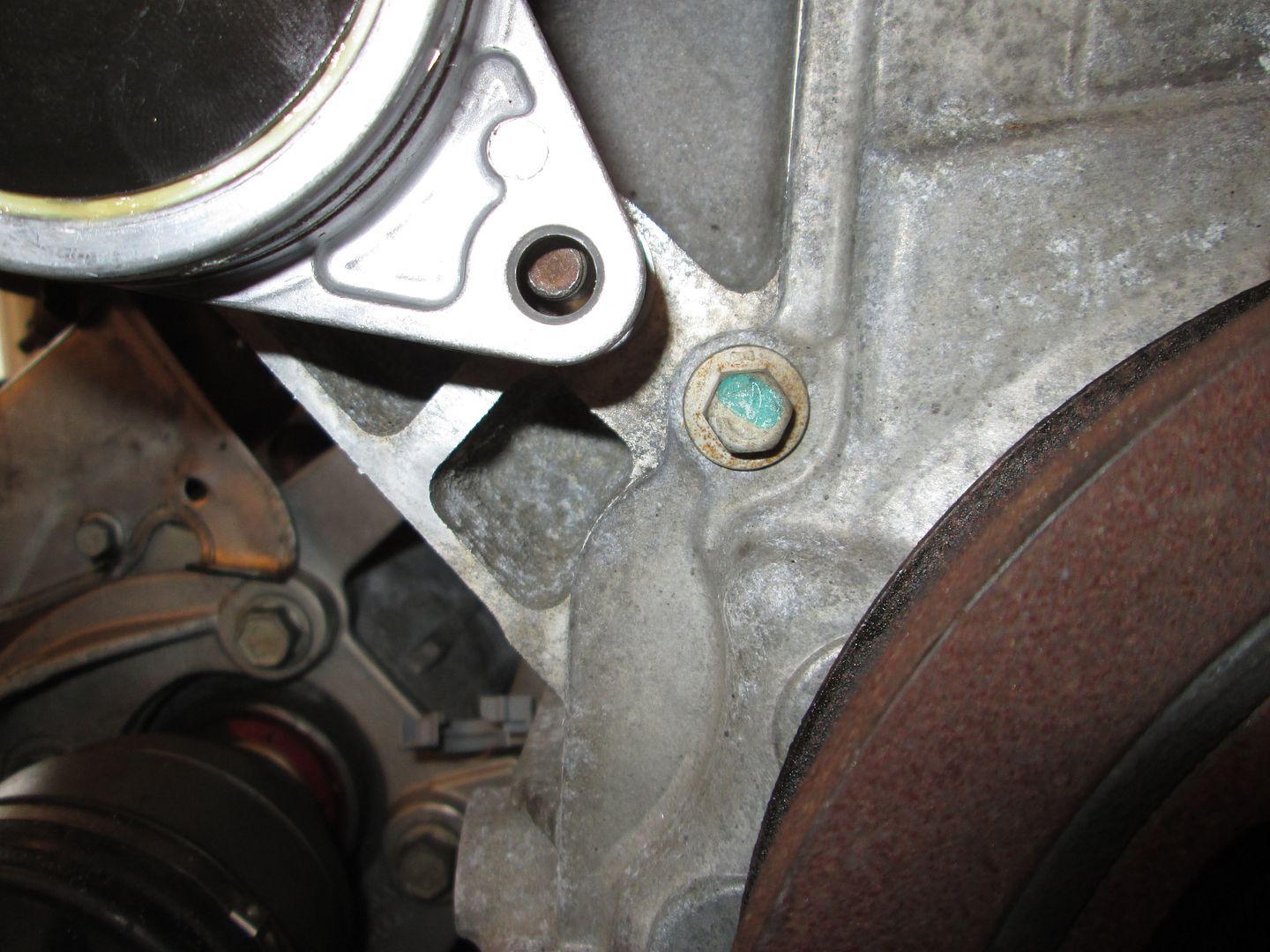
I would love to find a tensioner that could use both of these holes in the lower block:
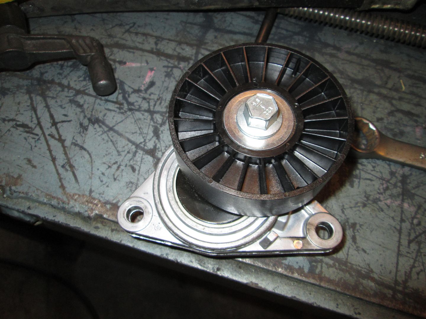
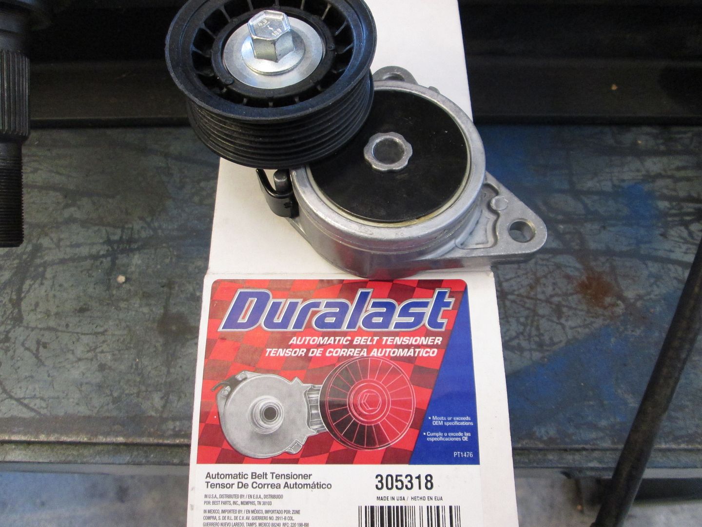
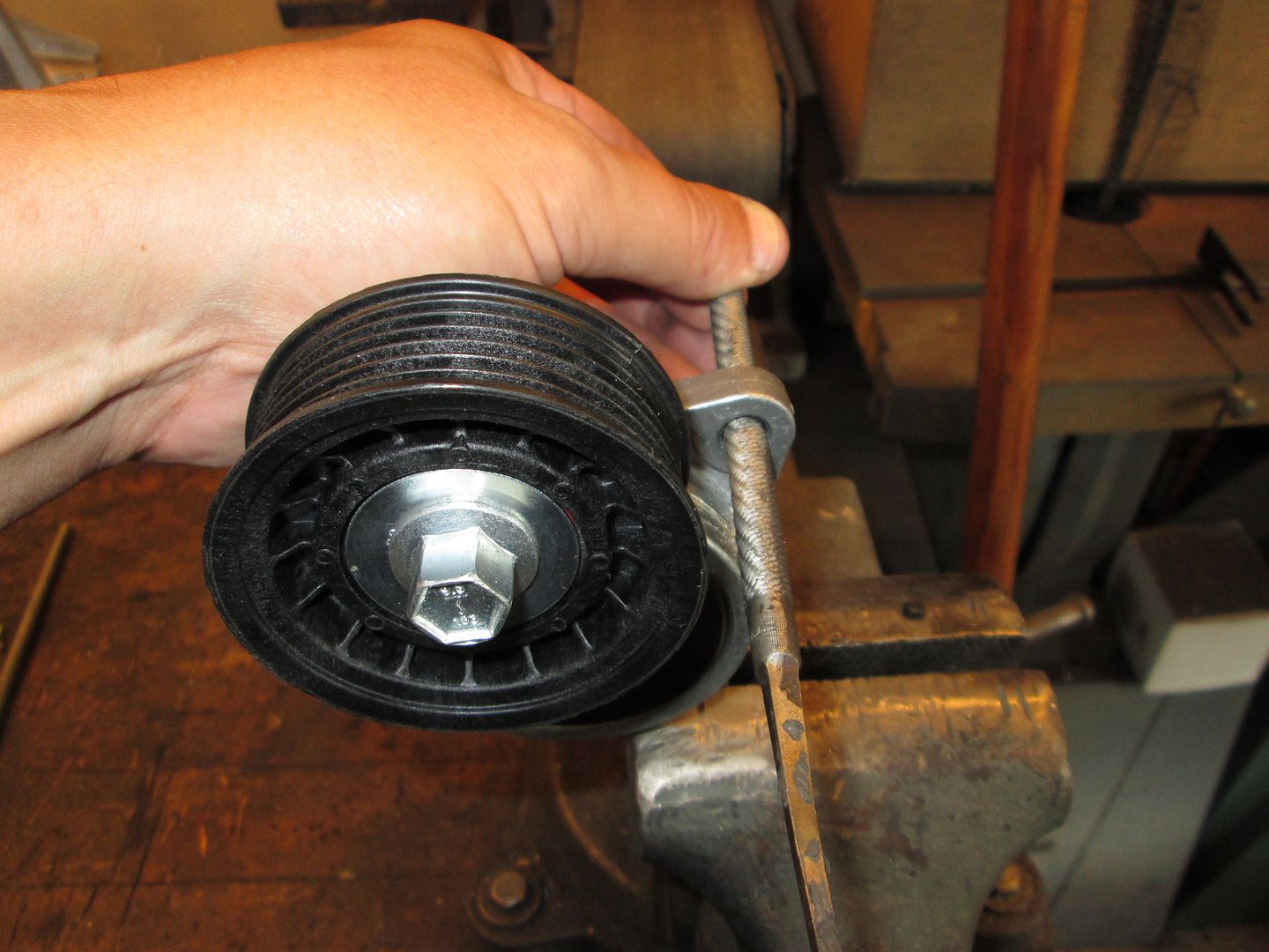
Here is the tensioner I use on almost all my swaps:
Unfortunately the bolt pattern is a little long to work with both of the holes in the block, but it can be used to show some options. Mounted like this, it would work as I want, but would require a custom bracket to mount the 2nd hole. The pulley would also need to be swapped out with a smaller ribbed pulley.
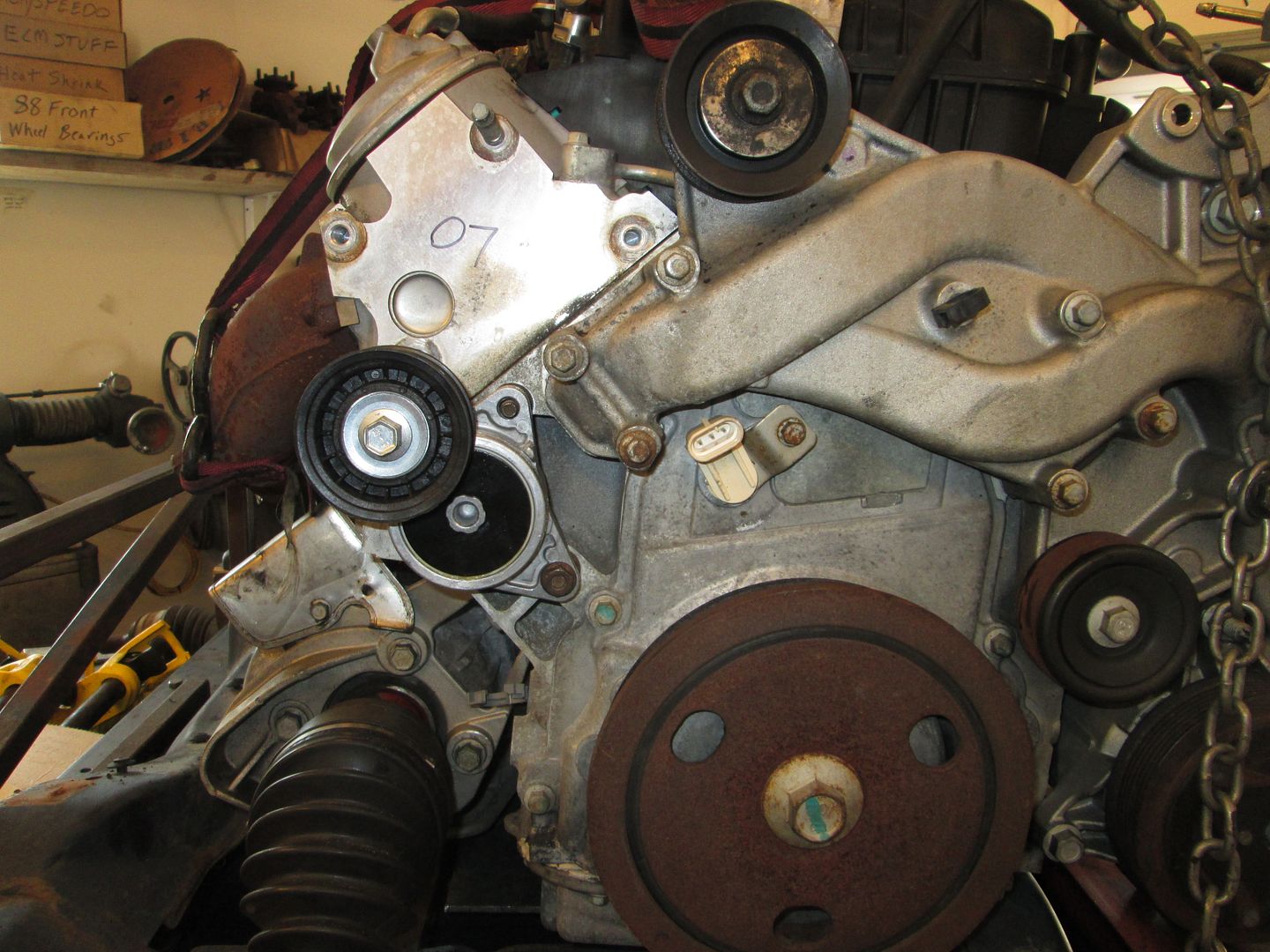
By flipping it, I can add another pulley above (from a hole in the head), but I think that new idler will hit the strut tower:
Over lunch on Tuesday I am going to go to the parts store and check out every tensioner they have in stock looking for something compact and hoping to find something with the needed bolt pattern spacing.
I have a West Coast Fiero reverse alternator mount that I removed from my first LS4 build. It made a lot of belt noise that I was unable to fix. If you are interested in it drop me a PM
Joe Sokol
------------------ 85 SE Daily driver with a 3.4 DOHC OBD II 88 Formula/GT 4.9 Allante Intake (My Baby) www.fieroking.com
I have a West Coast Fiero reverse alternator mount that I removed from my first LS4 build. It made a lot of belt noise that I was unable to fix. If you are interested in it drop me a PM
Joe Sokol
From what I have learned with my LS4, they are hyper sensitive to pulley alignment, and I think this is due to the short distances between all the pulleys/idlers.
I fought squealing issue on my setup for the first 6 months when it was driven in the rain until I figured out it was caused by excessive slop in the alternator mounting holes. I removed the belt, loosened the bolts and used a straight edge to verify the pulley was precisely vertical. The squeal has been gone ever since.
I haven't got to that part yet, but I plan to add some bushings to at least 2 alternator bolts to remove most of the slop in the alternator mounting holes.
As for the WCF bracket, I have seen pictures of it, but would prefer to do something slightly different. For me, figuring out these mounting issues is part of the fun in doing swaps!
My trip the other day to Autozone to check out tensioners was productive. I found a tensioner with the mounting spacing within .084" of the two holes I wanted to use and the right general shape (and it came with a 6 rib pulley too!).
Now the holes in the block are M10 and the holes in the tensioner are smaller, so I went to the bolt bin and found some studs with a smaller thread and put them in the block.
Install the tensioner so you can see how close it is to fitting:
I little file work to the insides of both holes:
Now it bolts on:
Between the mounting studs and the block, there isn't much more room for it to pull into the block:
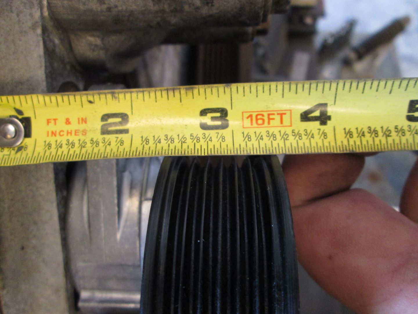
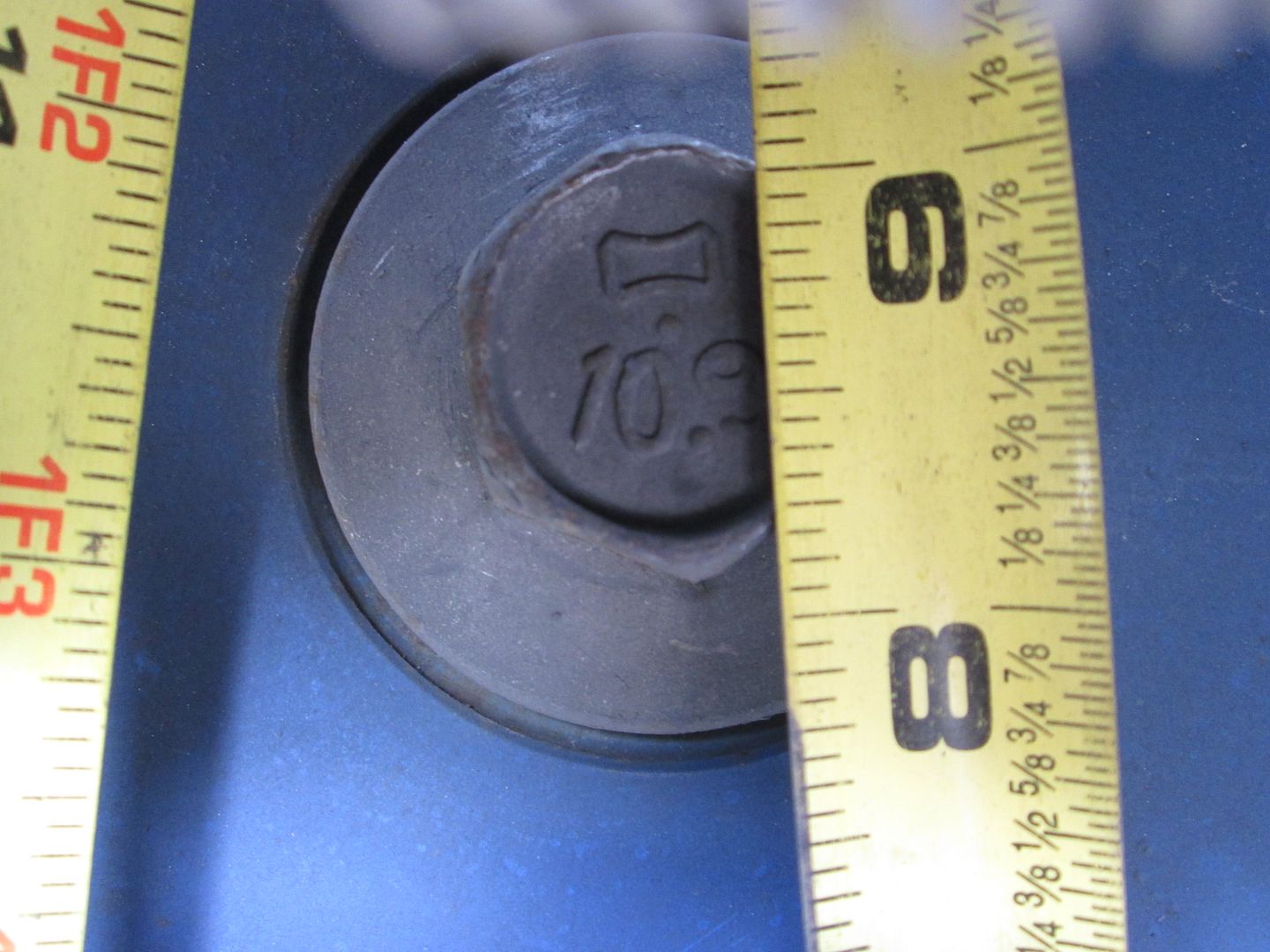
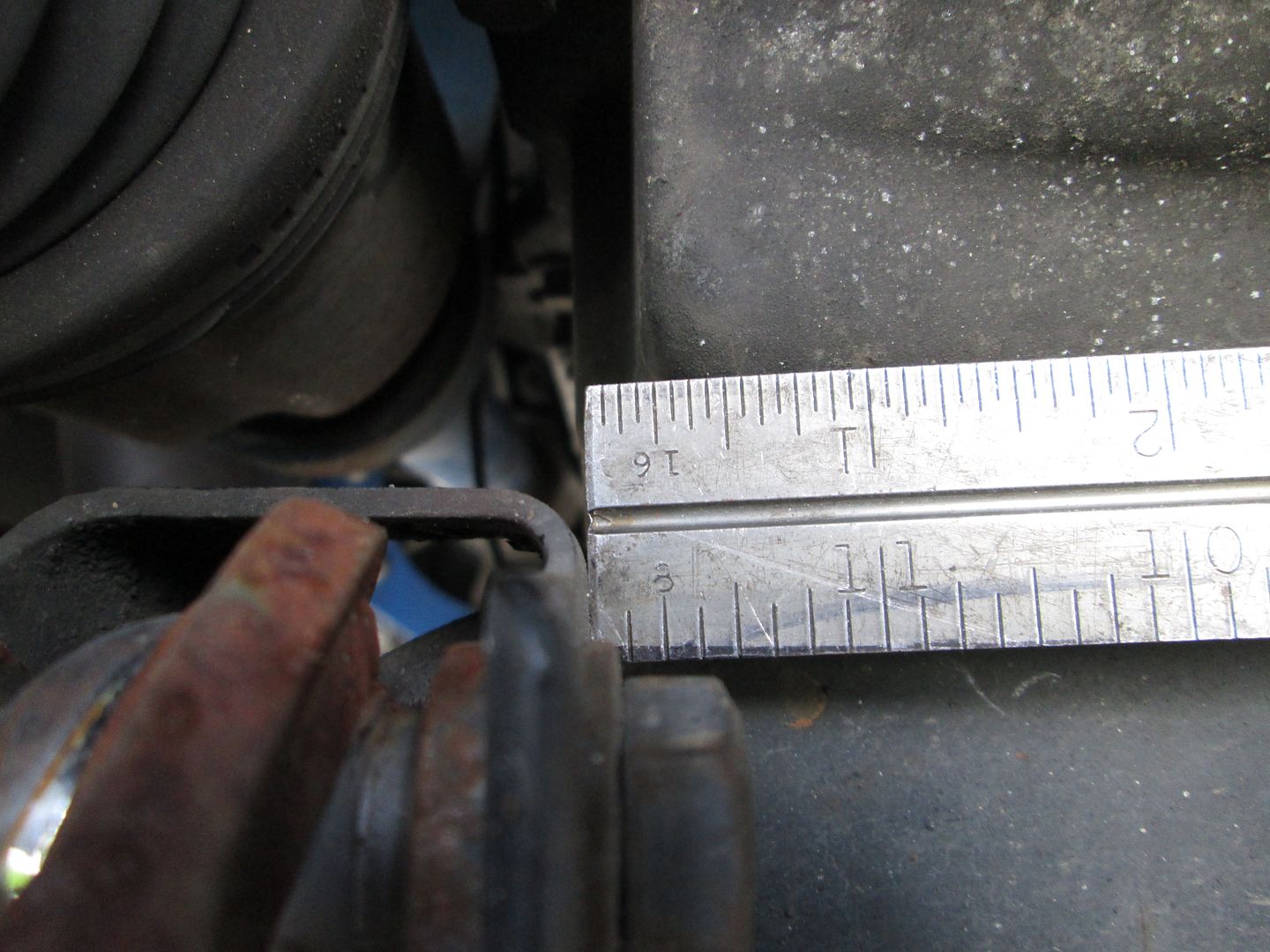
So I check where the pulley is in relationship with another one. Stock LS4 pulley from the head (focus on the point of the first rib to on the left - its just under 2 5/8"):
The new tensioner (right at 2 5/8" - this is very, very close. I could remove some material on the block to pull this in so it is perfect):
Then I pulled the tensioner to check range of travel. This is the only thing I am not super thrilled about, as the travel is limited and not the full range of motion for the tensioner, but it might still have sufficient travel to work.
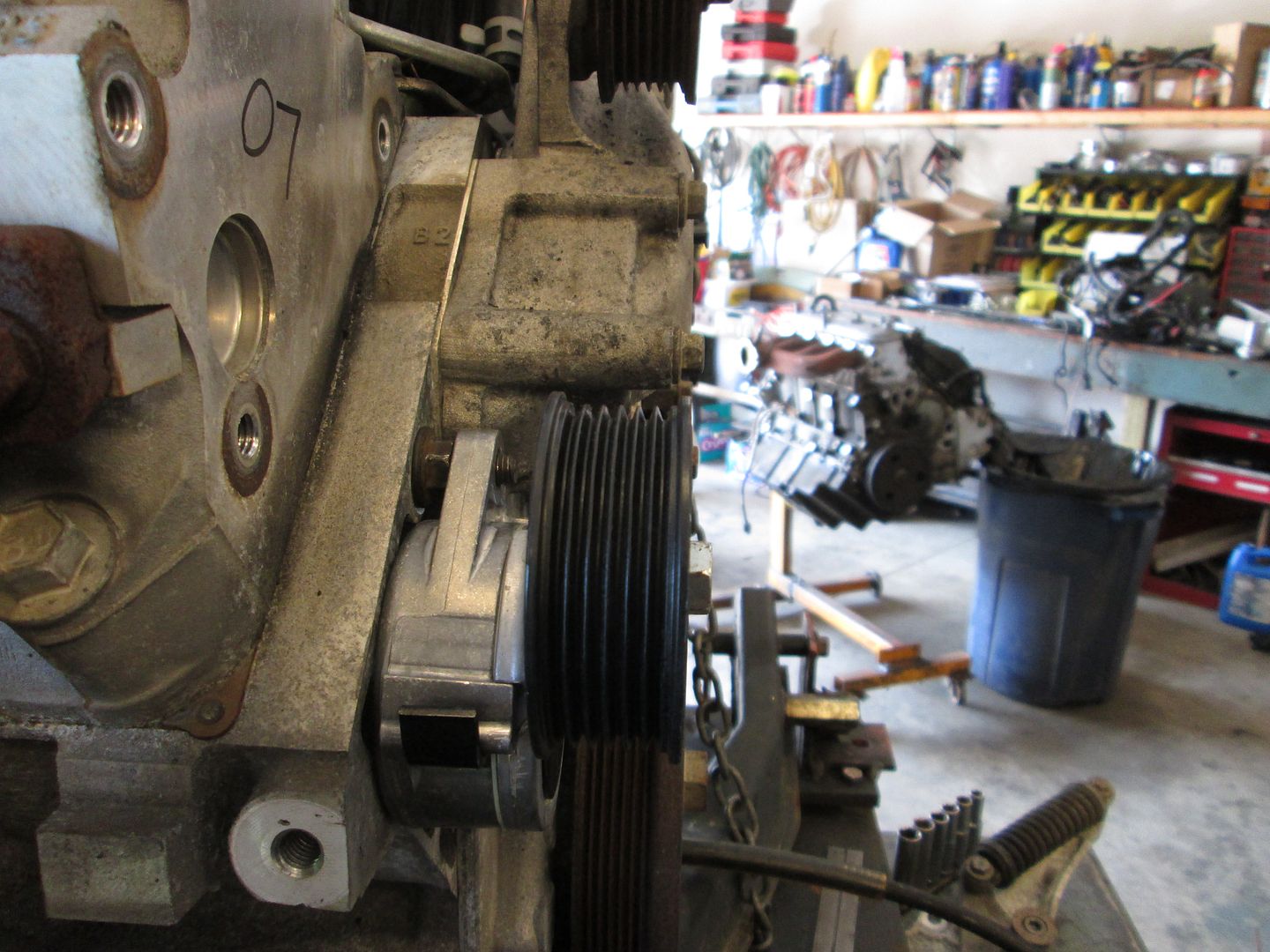
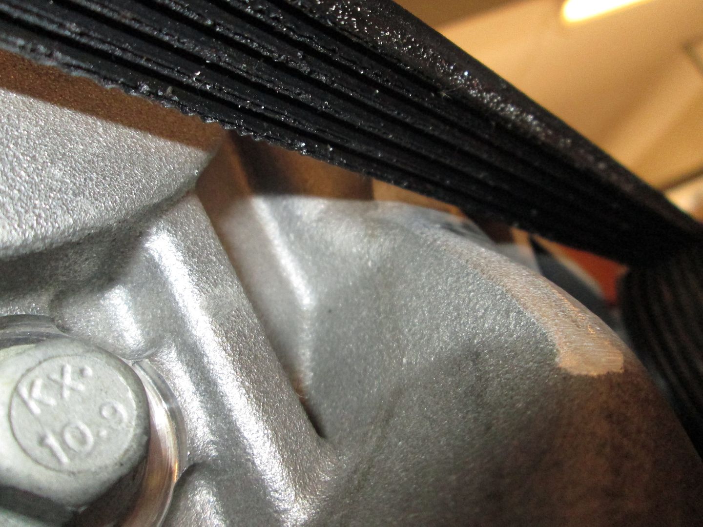
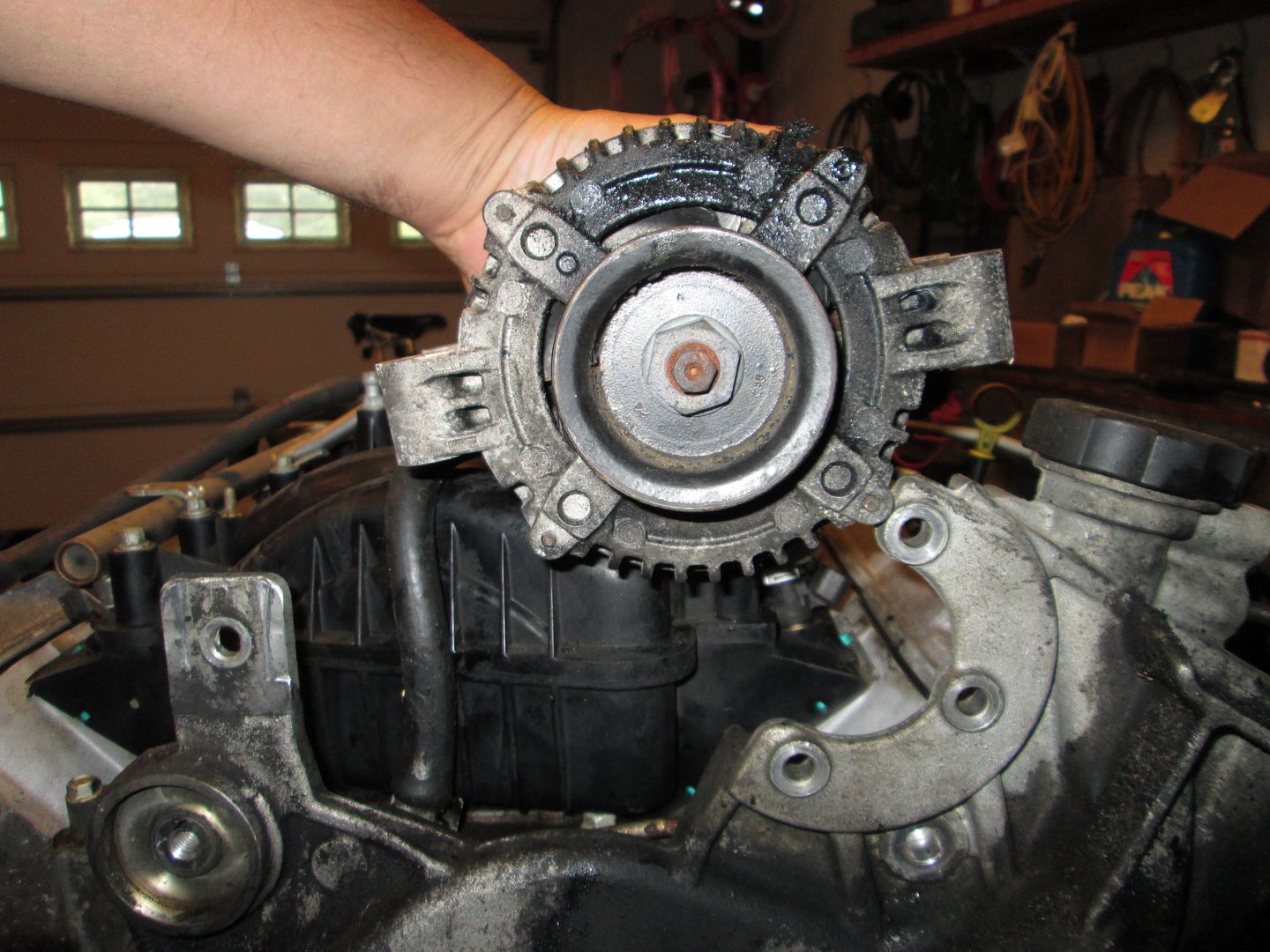
Here is a nice visual showing the idler pulley not sticking out past the water pump (except its bolt head):
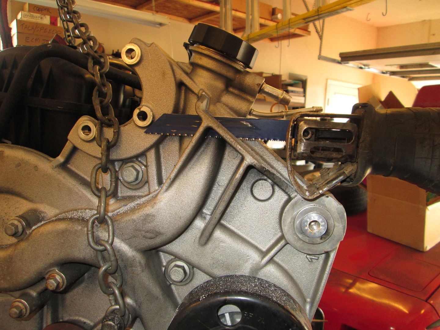
Then it was time for some cutting on the water pump to make room for the pulley relocation. I used a saws all for the 4 cuts: First cut from the topside:
Here you can see the piece has been removed the two cuts from the bottom that allowed it to separate:
4th cut to remove more material from the near vertical section:
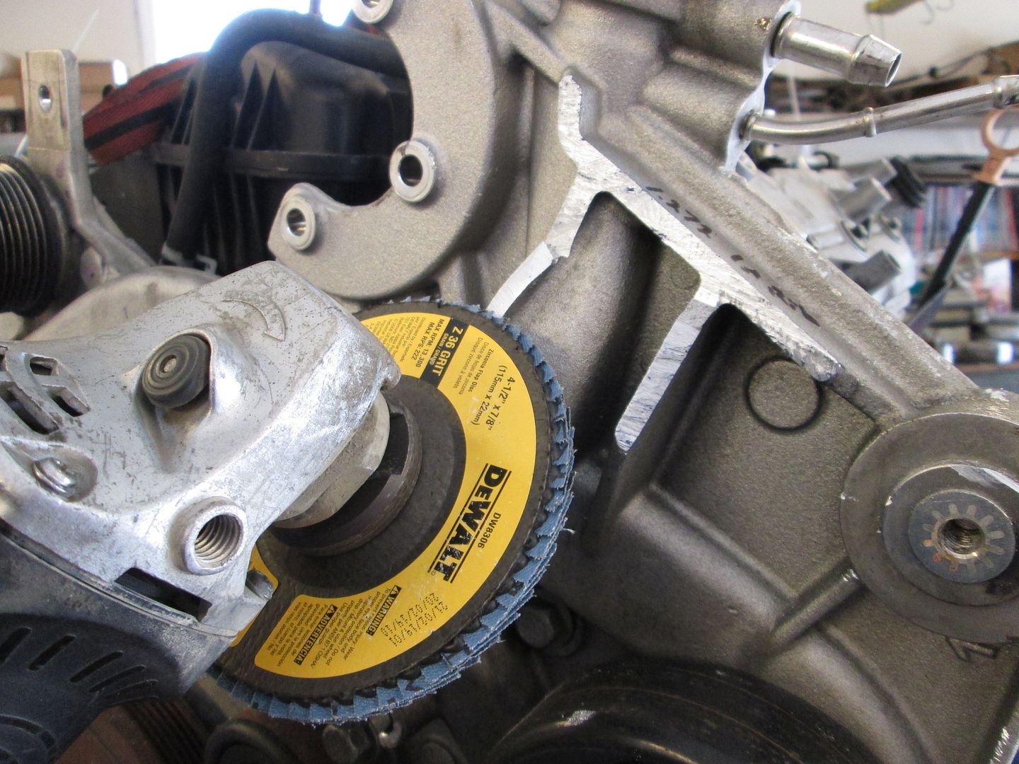
Grab the angle grinder with a 36 grit flapper disk and smooth things so it doesn't look like this area was modified. Taking this extra step to clean things up really helps with the visual appeal of the swap and only takes time (not $$$ - unless you are paying someone to do it).
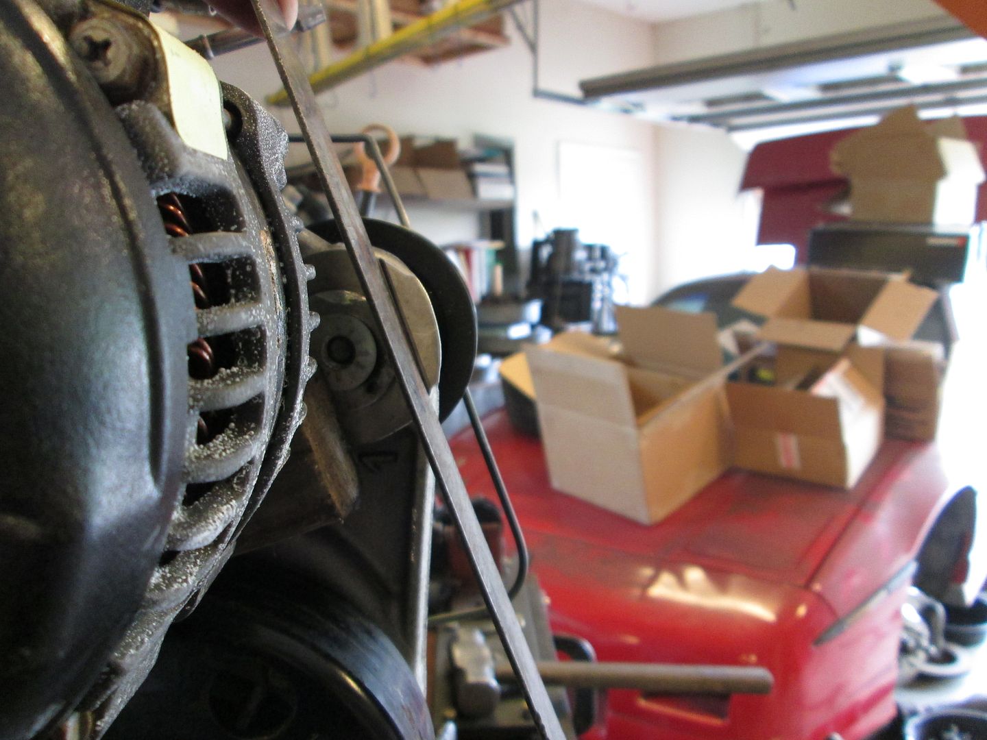
Then it was time to throw a belt on to show the belt path and check for clearance. It just barely clears... by raising the alternator pulley higher, this clearance will be increased to an acceptable level:
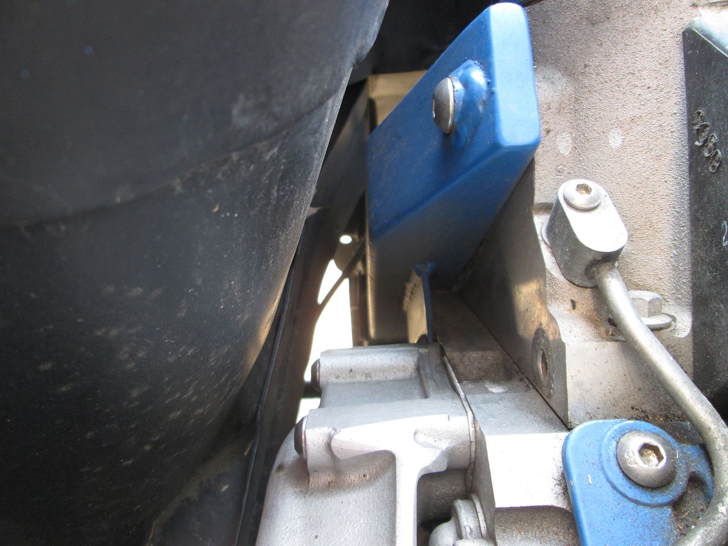
Then I decided to take some pictures of the available clearance in the car - its hard to tell anything by this pic:
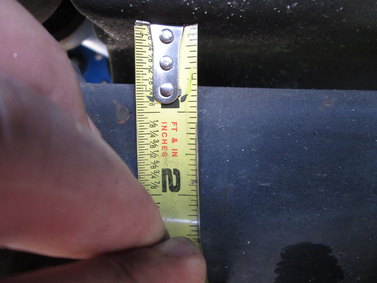
I needed a reference tool so I could better visualize if the tensioner would fit. So I used this scale. The position of it relative to the water pump bolts and center of the pulley is critical:
It just barely fits!:
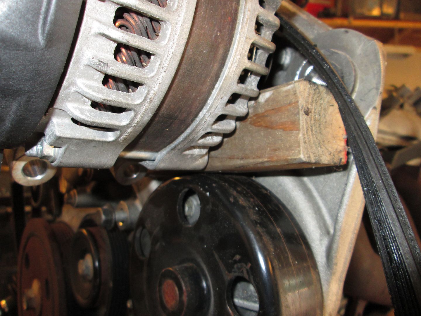
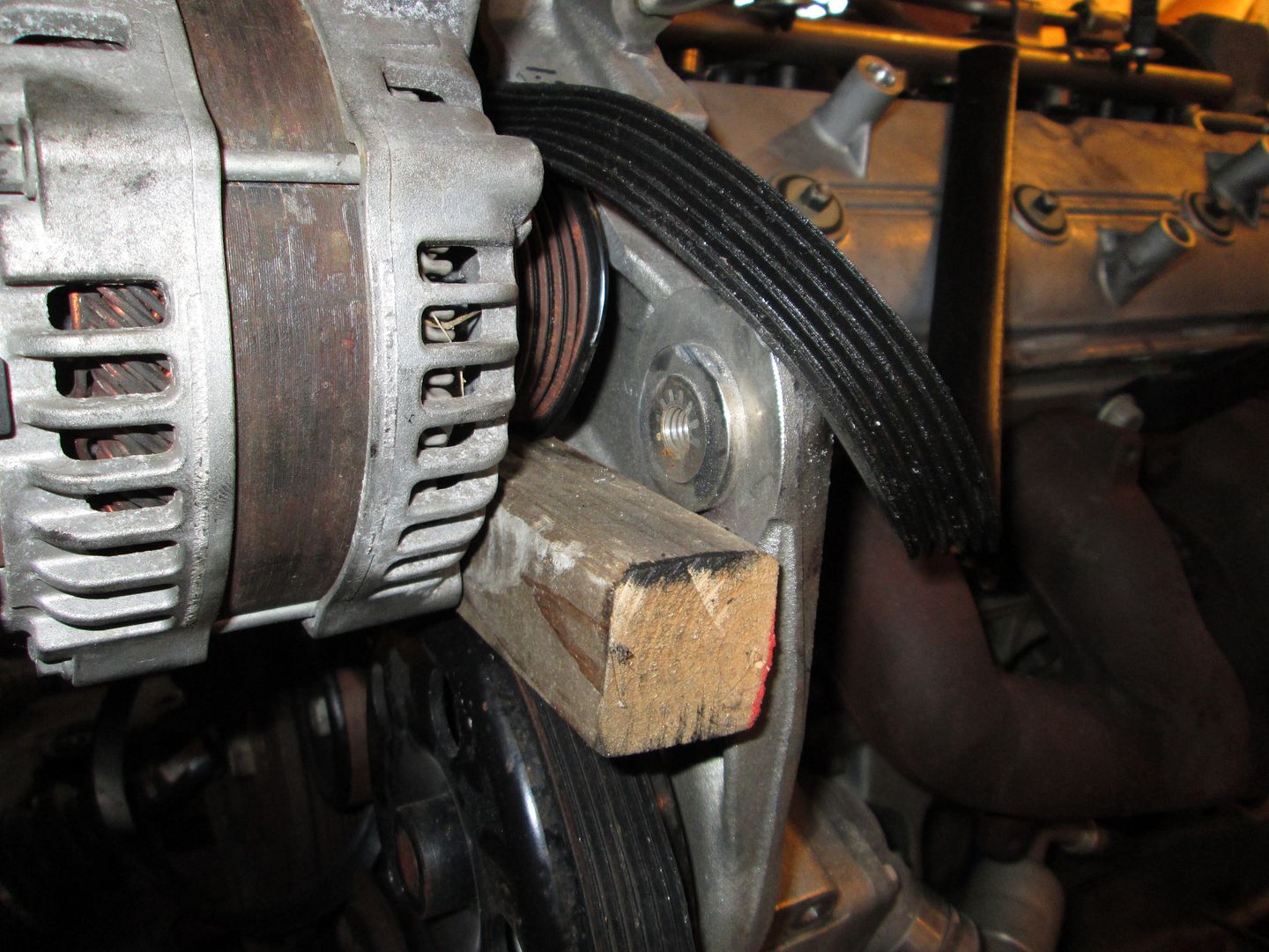
On to the alternator... using a piece of wood and some wire I was able to hang the alternator in the general area of where it needs to be and the red lines indicate a potential mounting method. What I like about this mounting method is the belt can be installed/removed w/o removing the alternator (power cable does need to come off):
With the alternator now higher than the original pulley, there is plenty of belt clearance to the body of the water pump:
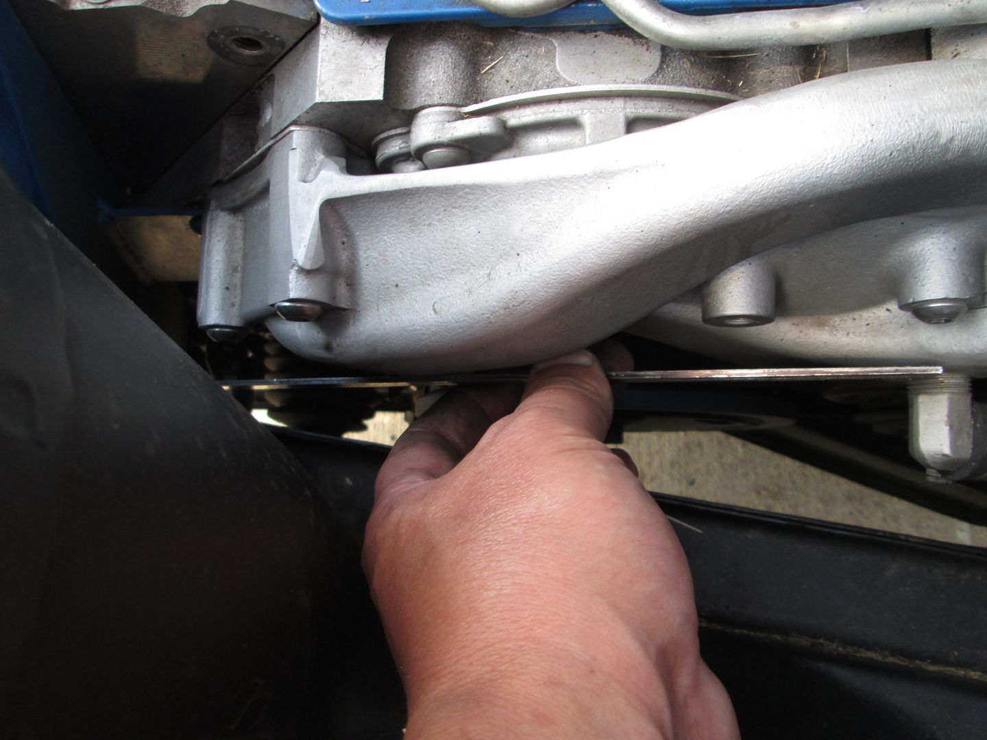
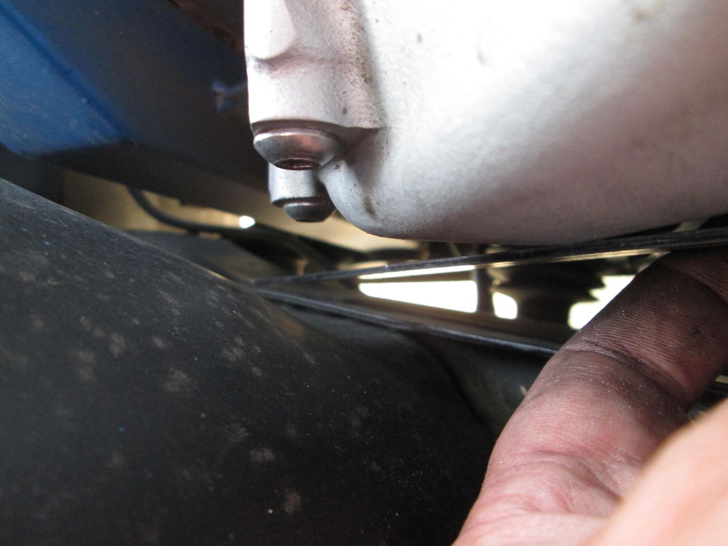
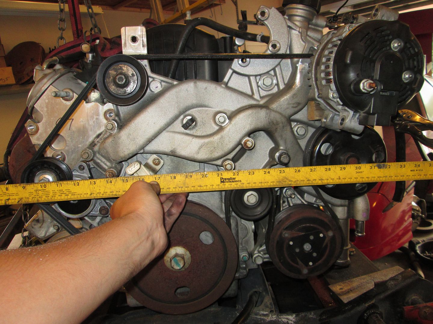
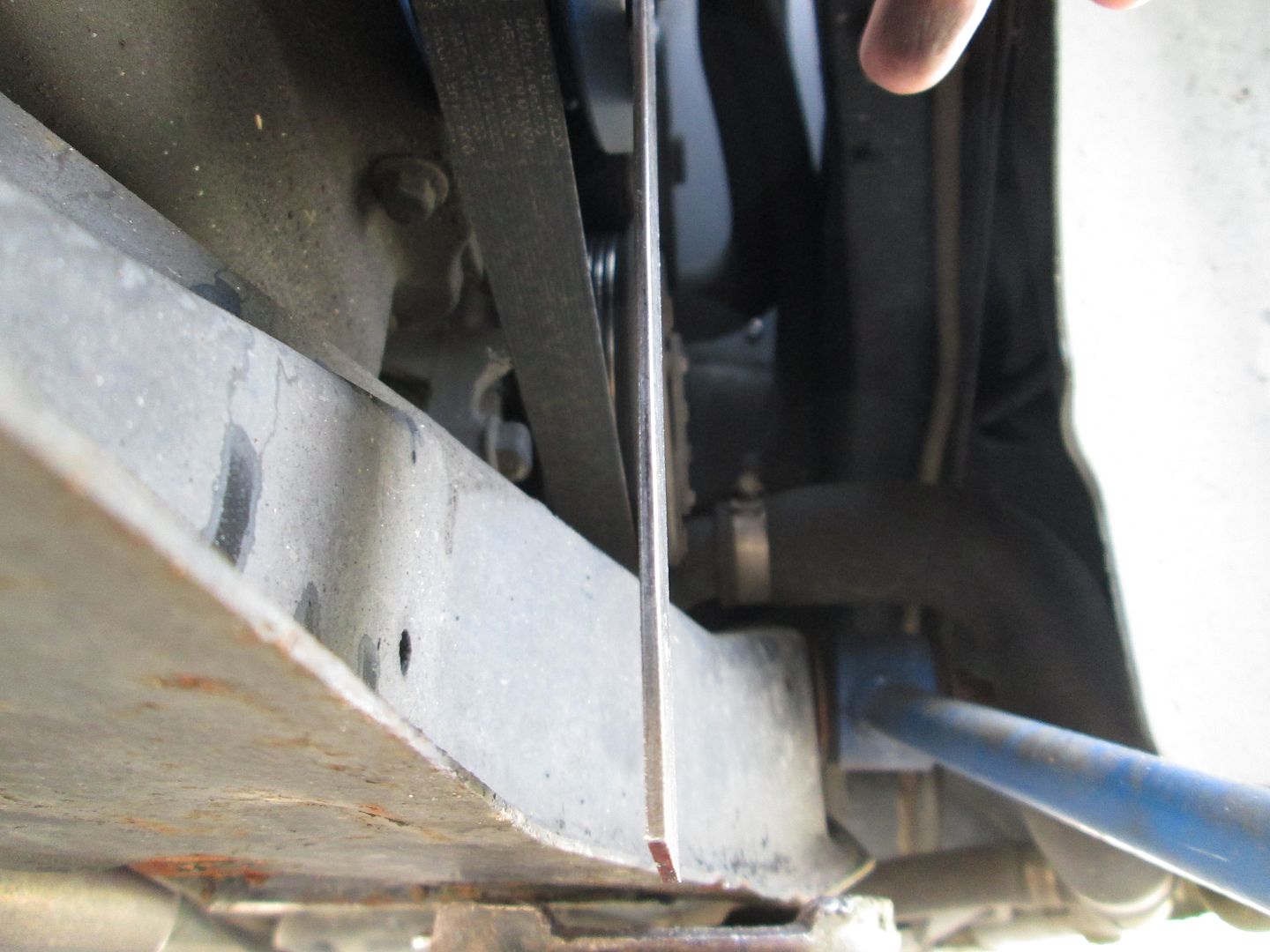
To make sure the alternator is above the frame rail, I checked the car using the water pump bolts as reference points and then placed this yard stick at the elevation of the frame rail... lots of room!
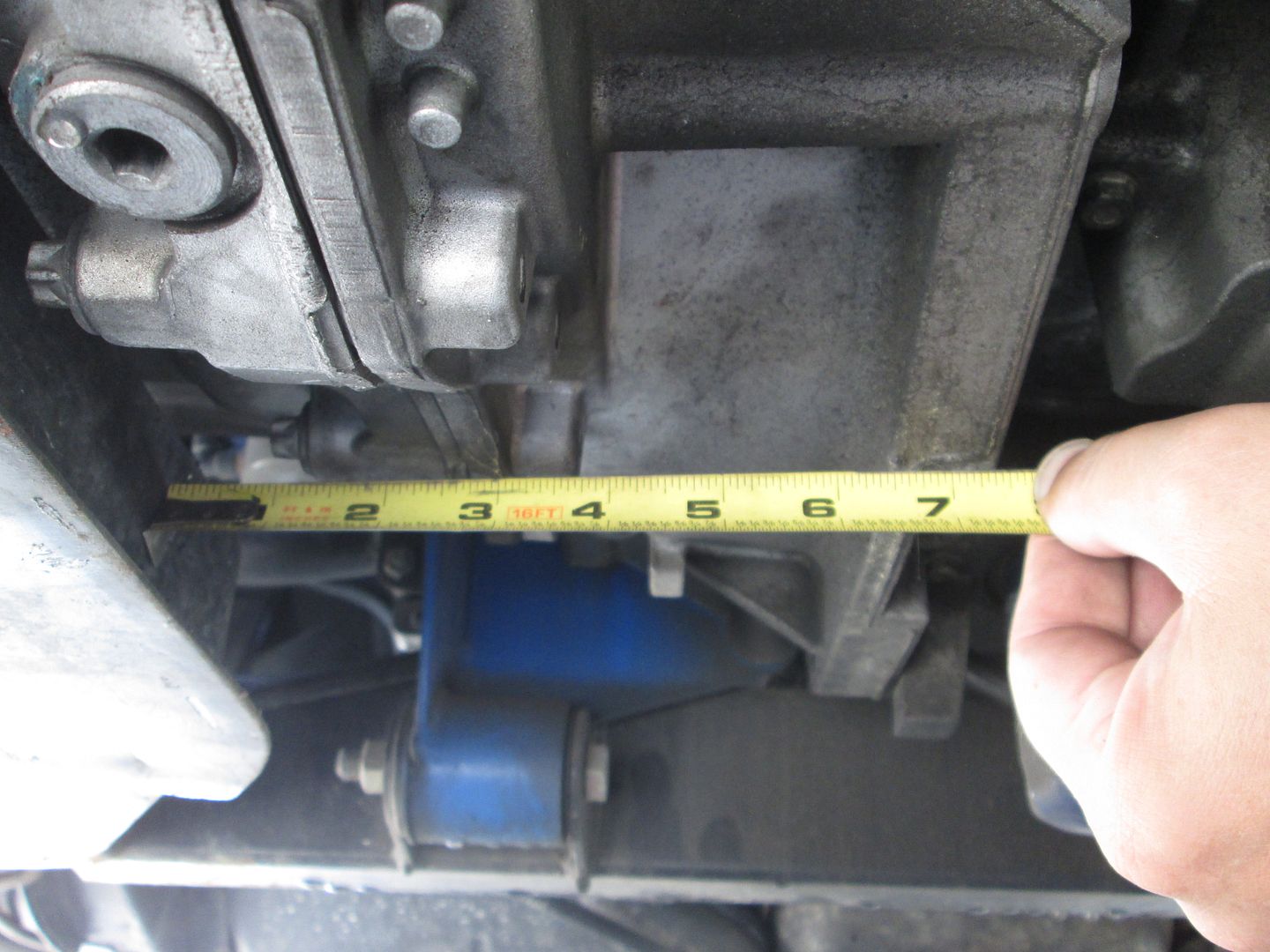
Here is how far the mounting tabs are from the water pump pulley:
Here is the distance from the pulley to the frame rail. Since the alternator is a few inches higher, it doesn't mean anything, but thought it good to show it anyway:
This tensioner and alternator location are showing some signs of promise. Now I am waiting on the M10 x 1.5 x 170mm bolts (the ones I previously ordered were M12 by my mistake)...
I am still going to keep looking for a more compact tensioner, but for $35 and 2 minutes with the file, this current one is very basic/simple and quite promising.
[This message has been edited by fieroguru (edited 08-06-2014).]
Didn't do much this evening, but did figure out that if I drill out the tensioner hole to 10mm I can use a longer bolt and spacer to mount another idler there and increase the wrap on the tensioner. This will help increase the amount belt slack the tensioner can take up with its reduced travel.
Actually, the more I think about it, there is no need to add the idler to increase the wrap of the tensioner, just run the belt like the stock LS4 routing (even easier and 1 less pulley).
there's no way to mount the tensioner on the same side as the rest of the accessories?
Ideally, the spring loaded tensioner should be on the slack side of the belt, which is the section between the harmonic balancer and the alternator. There isn't much room at the rear head location w/o modifying the strut tower, and there are no other readily accessible bolt holes until the power steering pump mount (3 bolt holes). Plan b is to find a round base tensioner to attach off the power steering mount. I would really like to find a tensioner with 2 pulleys so the tensioner will have a good amount of wrap (for belt takeup), while keeping the wrap around the alternator maximized as well.
If I wanted to run a mechanical tensioner, there are several with a jack screw. I could probably place it at the location of the idler between the balancer and AC compressor and have the threaded rod run vertical with the adjusting nut on the bottom side. However, then I would still need to make a bracket of some kind to mount the idler to get the belt from the balancer around the pump. So it would require periodic belt tensioning adjustment and require more fabbed parts...
The main criticisms of the LS4 swap is its too complicated and too expensive for most to accomplish and with this swap I am trying to find a path that more people could follow. This may not be the most ideal path to some, but simple, cost effective, and functional is what 80+% of Fiero swappers are looking for and those are my key parameters.
While figuring out the belt drive, I am trying really hard to keep the required mods and cost of the needed parts to an absolute minimum. Right now the tensioner is $35 (and comes with the right pulley) and takes very minor work with a file to attach to existing holes. Cutting the pump housing by the fill area takes 10-15 minutes with a sawsall (or other cutting tool) and a grinder to clean it up. I could have done it with a cutoff disk and the grinder... but with the engine up that high the position I needed the grinder to be in wasn't easy (would have been quite simple had the engine been on the ground). The alternator will require a custom bracket, but the 3800 swaps have proven than most people are willing to pay for an alternator relocation bracket, or build one themselves...
I think as long as the accessory drive is simple to mod (no welding aluminum) and the other parts are relatively inexpensive and bolt on, then I will have accomplished my goal. My personal struggle to do all that while making it look clean and professional.
[This message has been edited by fieroguru (edited 08-08-2014).]
Enjoying following your newest build thread Building a cantilevered alternator mount for my Ls4 was fun/challenging. Getting enough wrap on the alternator verses the water pump verses the alternator to firewall clearance and all those appendages on that alternator Looking good, cant wait to see what you come up with!
Originally posted by fieroguru: Ideally, the spring loaded tensioner should be on the slack side of the belt, which is the section between the harmonic balancer and the alternator. There isn't much room at the rear head location w/o modifying the strut tower, and there are no other readily accessible bolt holes until the power steering pump mount (3 bolt holes). Plan b is to find a round base tensioner to attach off the power steering mount. I would really like to find a tensioner with 2 pulleys so the tensioner will have a good amount of wrap (for belt takeup), while keeping the wrap around the alternator maximized as well.
I was looking at that picture of the belt setup earlier, and started wondering. Will an alternator fit in the power steering pump mount location? Or will it interfere with the intake? The alternator on my Avalanche for example, mounts in a similar location as to where the P/S pump is on the LS4, and in a similar way. If the distance center-to-center for the top and bottom bolt holes on the P/S pump bracket are the same as for the alternator mount on the Vortec engines, it might be possible to use one of the truck alternators on the LS4 in that location, assuming the pulley sticks out the right amount for the LS4 belt.
Installing a larger diameter pulley on the alternator (if Possible), could eliminate the top right idler and retain a good wrap on the alternator and water pump.
Originally posted by dobey: Will an alternator fit in the power steering pump mount location? Or will it interfere with the intake? The alternator on my Avalanche for example, mounts in a similar location as to where the P/S pump is on the LS4, and in a similar way. If the distance center-to-center for the top and bottom bolt holes on the P/S pump bracket are the same as for the alternator mount on the Vortec engines, it might be possible to use one of the truck alternators on the LS4 in that location, assuming the pulley sticks out the right amount for the LS4 belt.
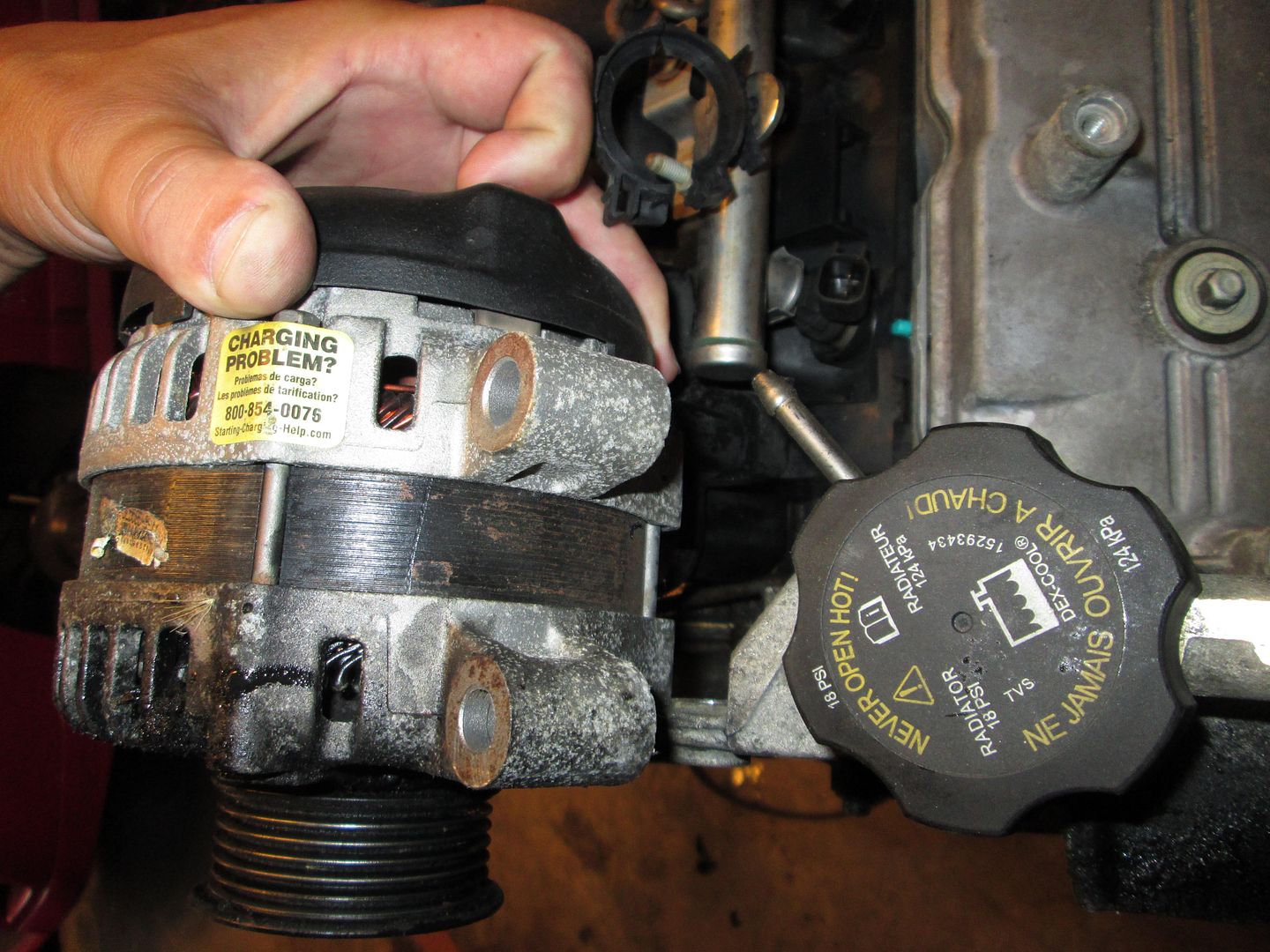
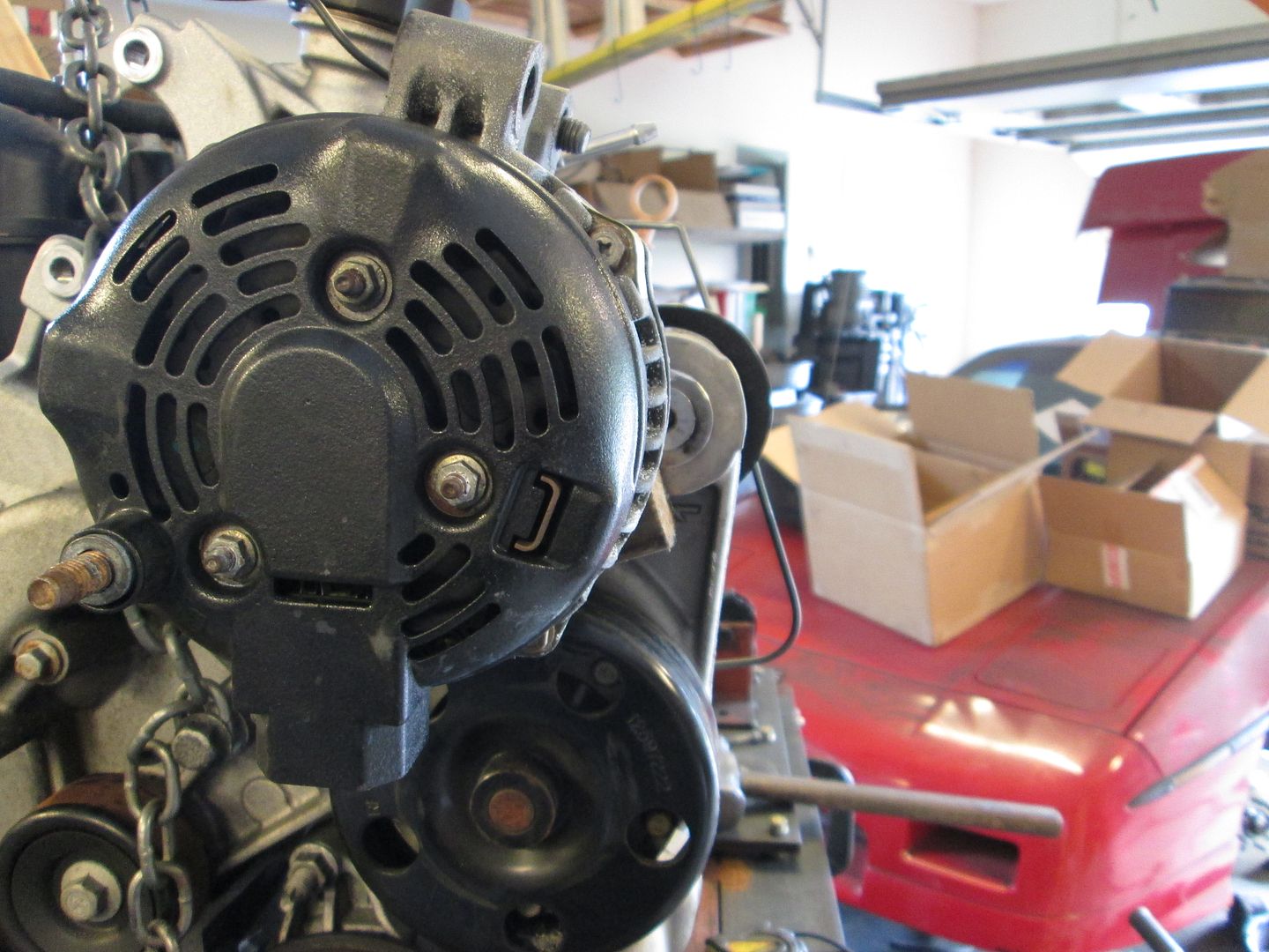
No room. The LS4 belt is something like 3" closer to the engine, so the alternator would be about 3" deeper into the space for the intake. In the name of simplicity and cost, I want to keep the alternator that comes with the engine. Here are some mockup pics. I might be able to get it 1/2" lower, but it is well into the decklid hinge area.
quote
Originally posted by Jims88:
Installing a larger diameter pulley on the alternator (if Possible), could eliminate the top right idler and retain a good wrap on the alternator and water pump.
The upper right idler pulley is already gone and will not be used. It is a very tight fit getting the stock alternator pulley to fit between the coolant path in the pump and the water pump pulley, while at the same time keeping the body of the alternator away from the rear glass and the angled firewall... It is a very tight fit, but I will see if a larger pulley will work (free up more HP!). I am more concerned with the wrap on the alternator than the wrap on the water pump.
Yeah. For some reason when I looked at your picture the P/S pump bracket looked bigger than it actually is. Just measured the alt bolt circle in my truck, and the P/S bracket on the LS4 manifold, and indeed, there's no way it would fit.
Is there room with the LS4 to mount it in the stock Fiero alternator location? Or is there definite interference with the strut tower in that area too? If it can avoid interference with the axle and exhaust as well, it looks like one could possibly be squeezed in over there...
Is there room with the LS4 to mount it in the stock Fiero alternator location? Or is there definite interference with the strut tower in that area too? If it can avoid interference with the axle and exhaust as well, it looks like one could possibly be squeezed in over there...
Many (almost every LS4 swap) have done the low/rear alternator mount and I will be making one of those as well. The only downside is you have to notch the PS frame rail to fit it.
[This message has been edited by fieroguru (edited 08-09-2014).]
Converting the idler to drive could free up some options?
It is a neat idea, but the further the alternator gets from the mounting bolts on the water pump, the easier it will deflect (or the beefier/heavier the mount needs to be). I am pretty sure I can mount the alternator where it is currently mocked up. One additional challenge I figured out today is for the alternator body and the water pump pulley want to occupy the same space (much less allow room for a belt to slide between the two for replacement) with the alternator pulley properly aligned. So either the alternator has to go up to clear the pulley or I space the pulley about 3/16" on the alternator to make the needed room.
The longer bolts didn't come in today, so can't do much more on the alternator mount. On Sunday I will probably pull the cradle off the fixture and make the needed modifications to get the engine to sit within the cradle. I might even jack my LS4/F40 car up and take some reference measurements on its engine placement so I can see if the LS4/4T65e-hd can fit in the same place.
[This message has been edited by fieroguru (edited 08-09-2014).]
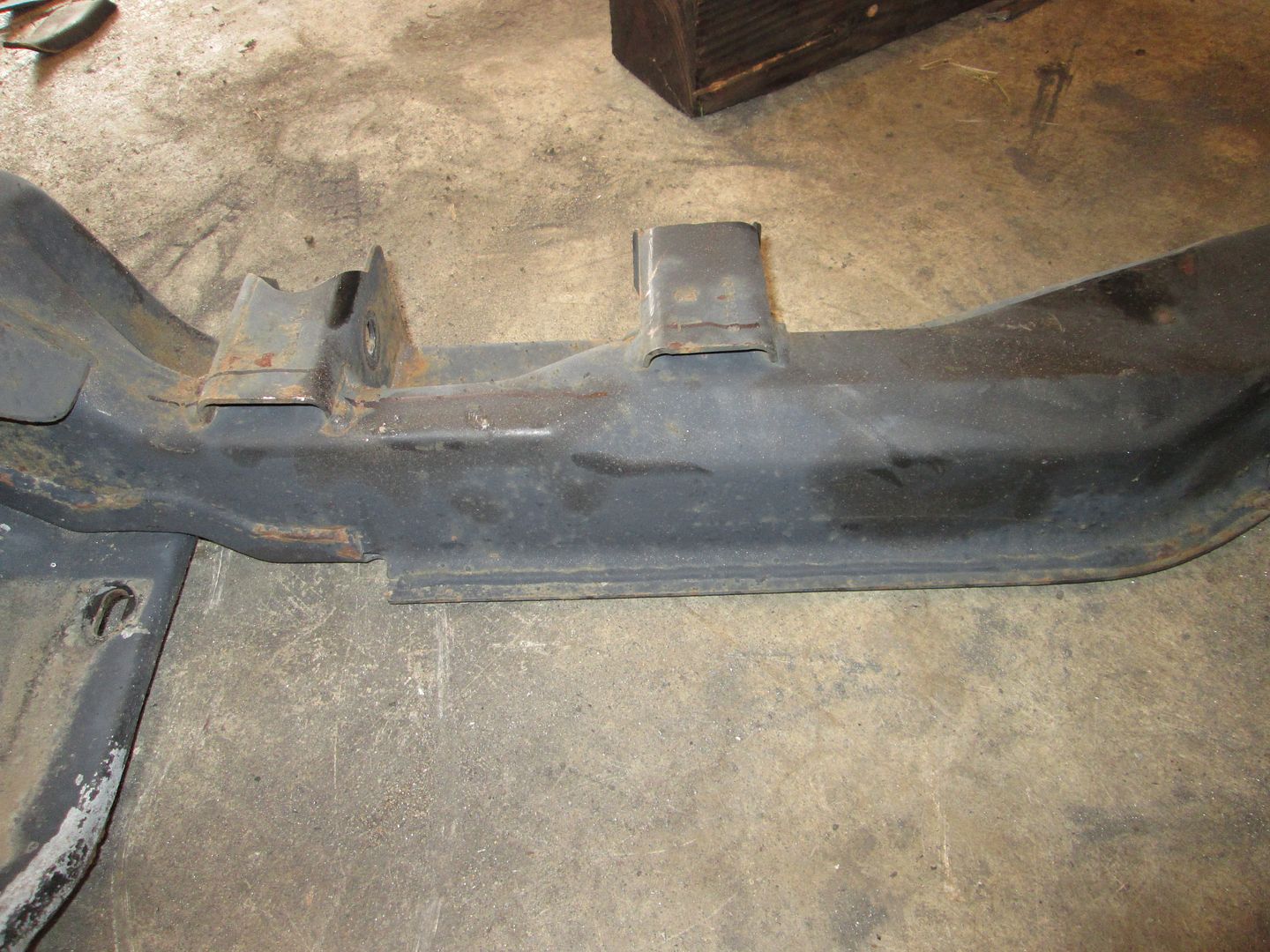
So I did some hacking on the cradle to eliminate most of the clearance issues.
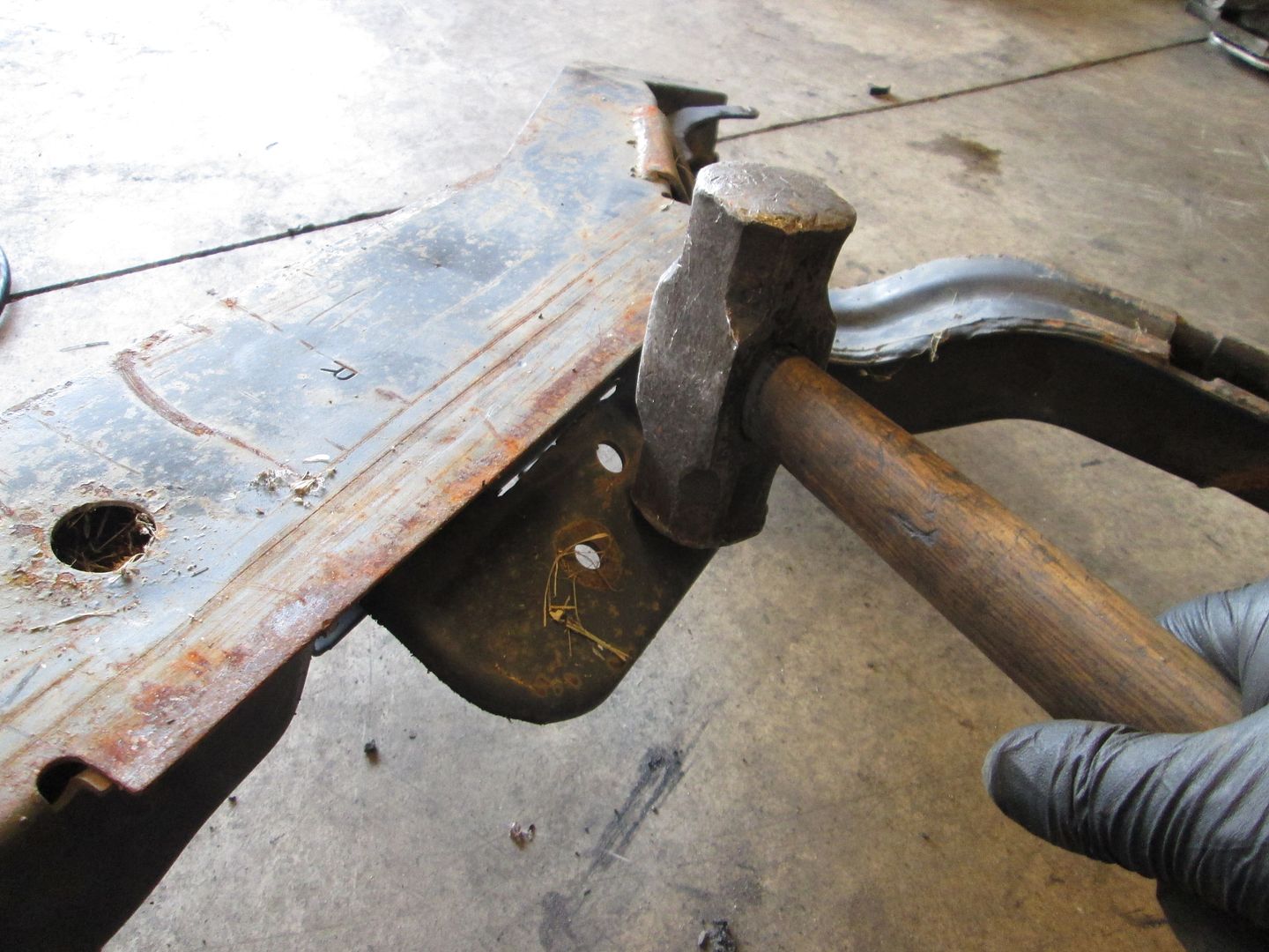
I started with the stock 88 engine mount. It has 7 welds holding it on, so I make some strategic cuts to the mount so I can pry individual sections against their weld and break them free. All I used for this was the hand held grinder and a cutoff disk.
I start with the top two welds and cut the flange like so. then I can use a large crescent wrench to grab the tab and bend it back & forth till is snaps off. Since I had easy access to the welds, I scored them with the cut off wheel to make them easier to break free.
Then I worked on the two vertical welds. I cut the bracket horizontally to free it from the base and then could bend the tabs to snap them free.
Now there are only the three welds for the base. Using the cutoff disk cut right down the center of the middle weld and score the two horizontal weld. Then flip it over, smack it with a hammer and work it back and forth till it snaps free.
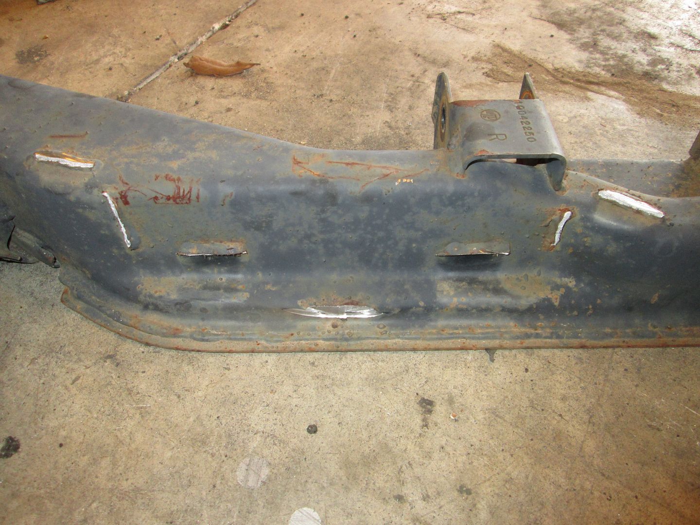
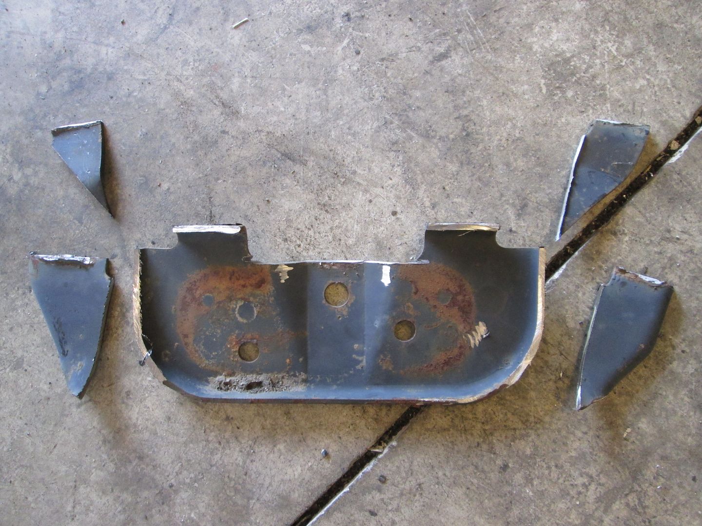
Here the mount is removed:
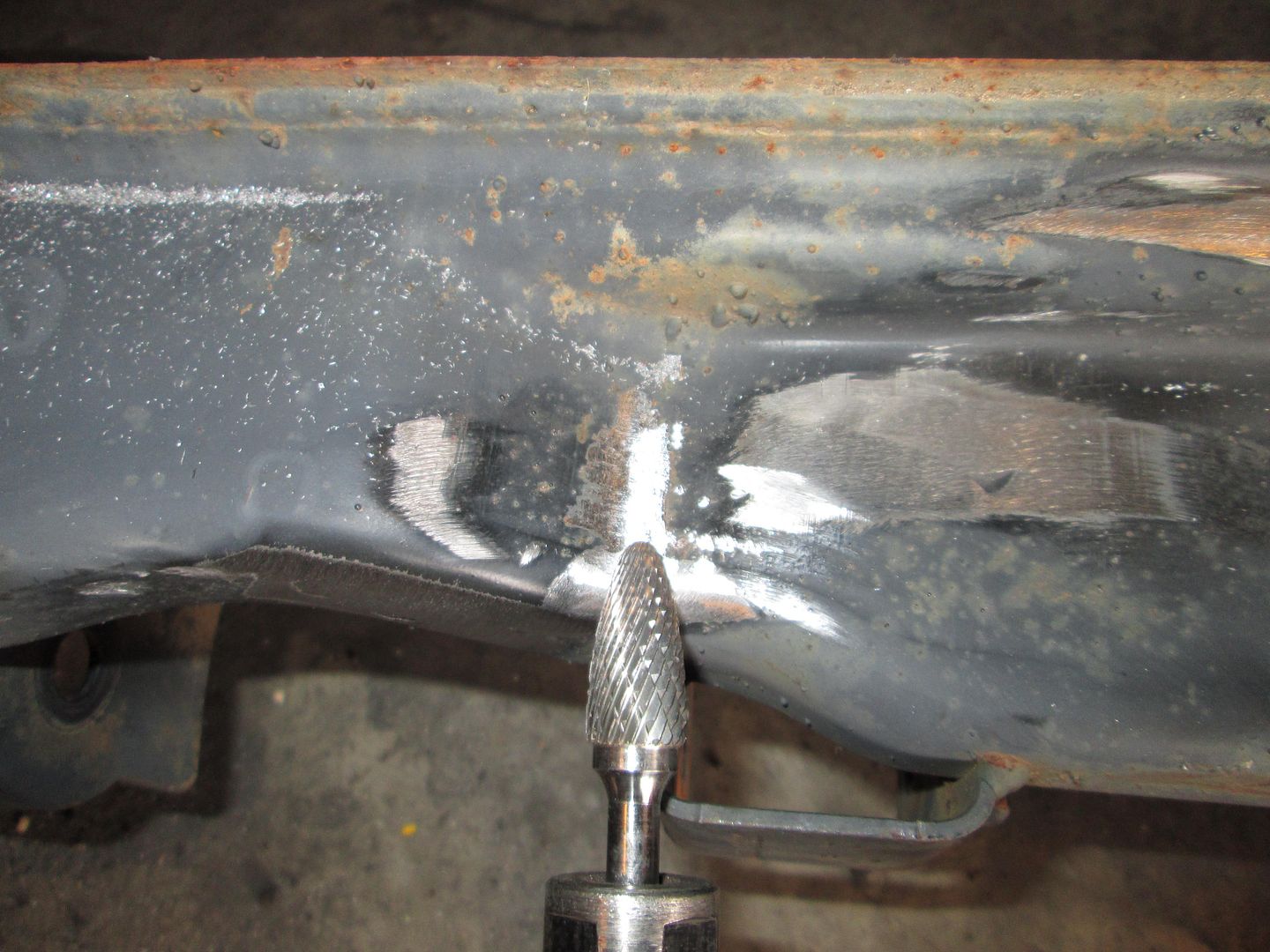
Now, there really is no need to do any more to the removed mount section, but being my normally fussy self, I grind all these welds smooth. The only tricky one is the front vertical one and I use a carbide burr to smooth it out (no room for the flapper disk).
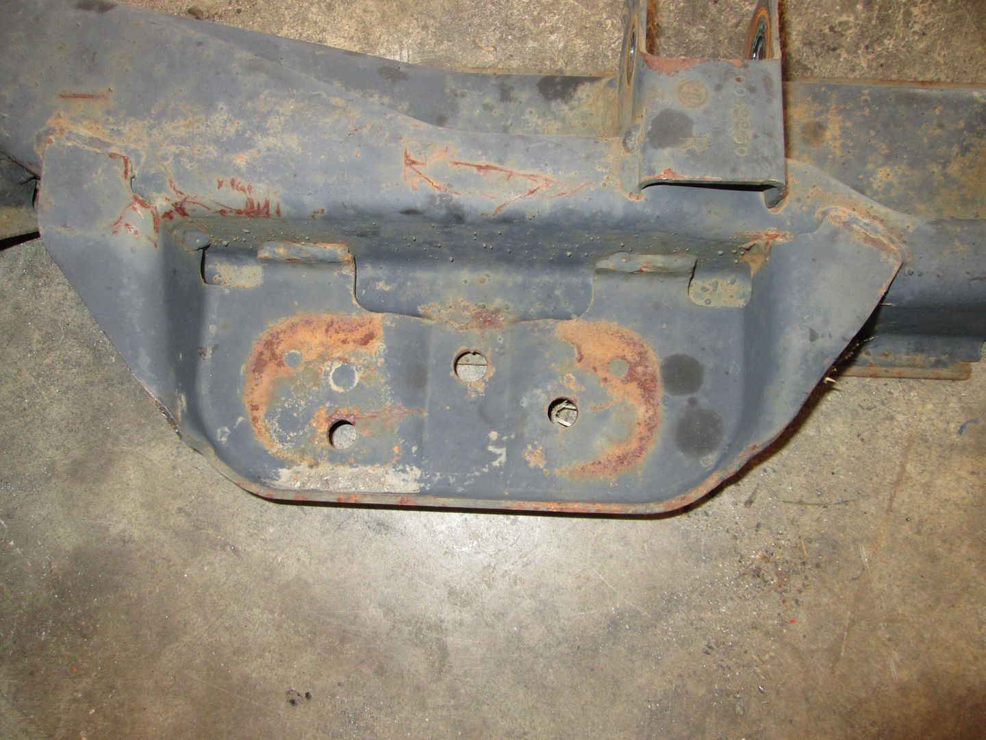
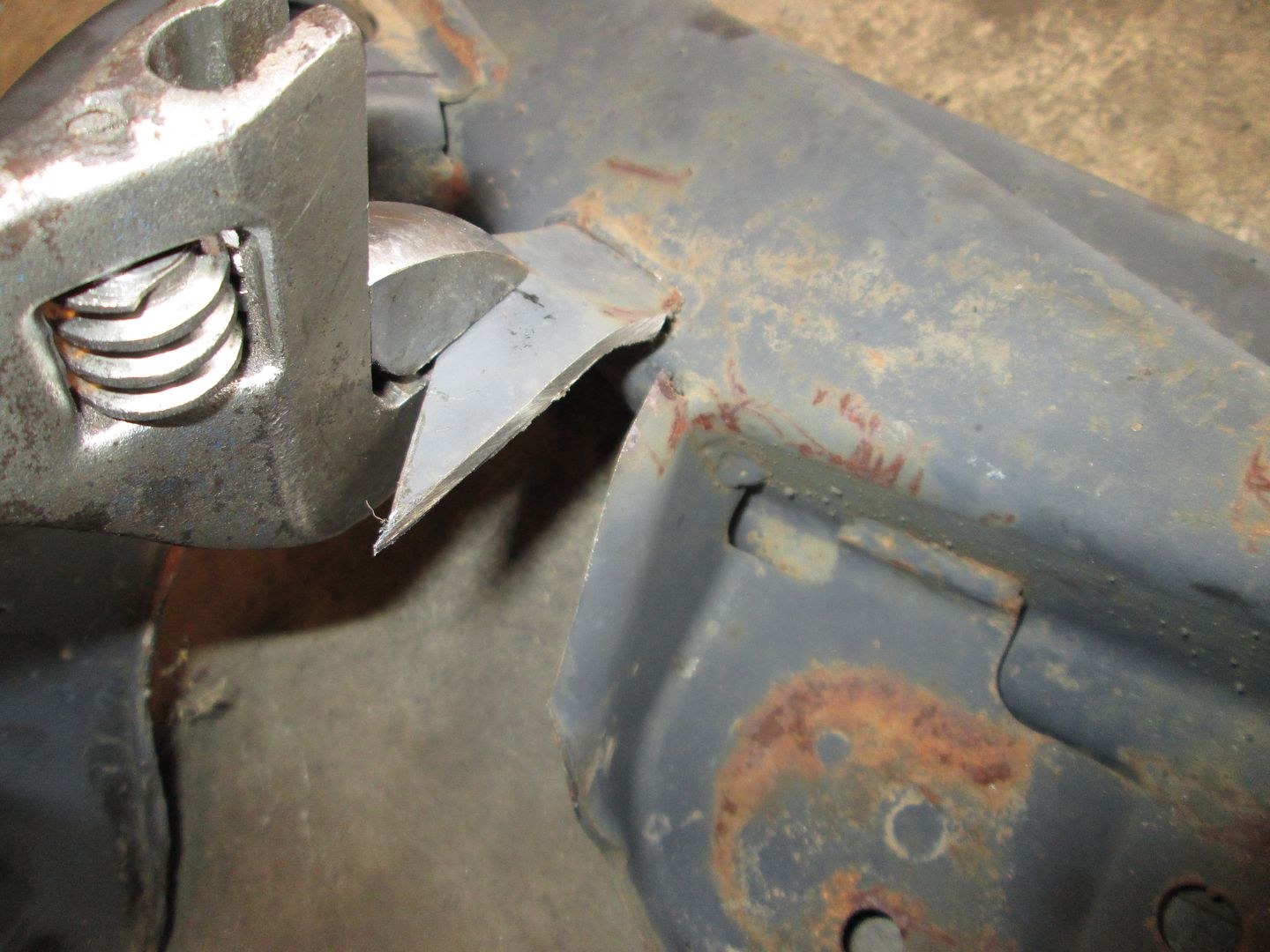
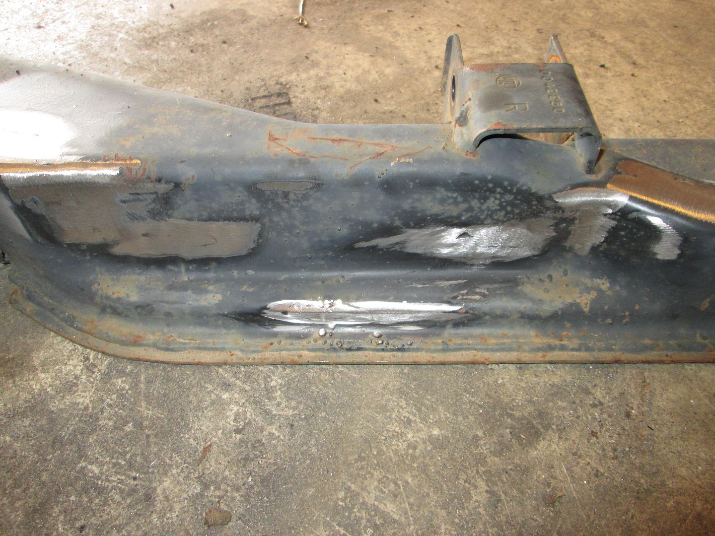
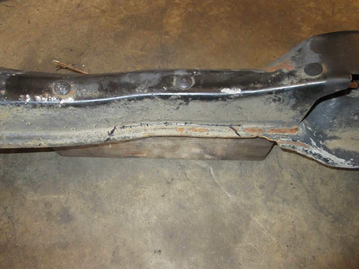
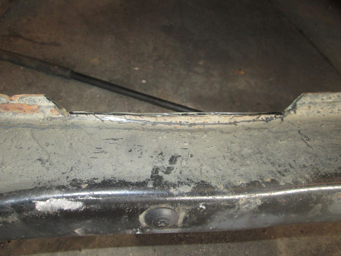
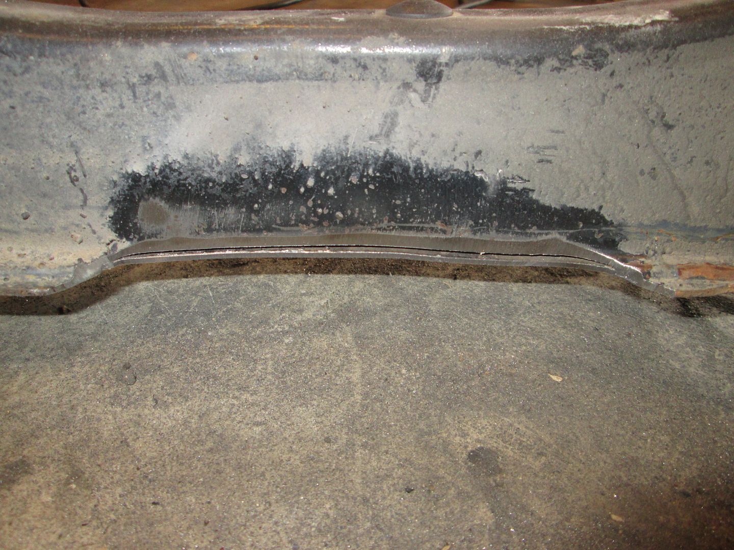
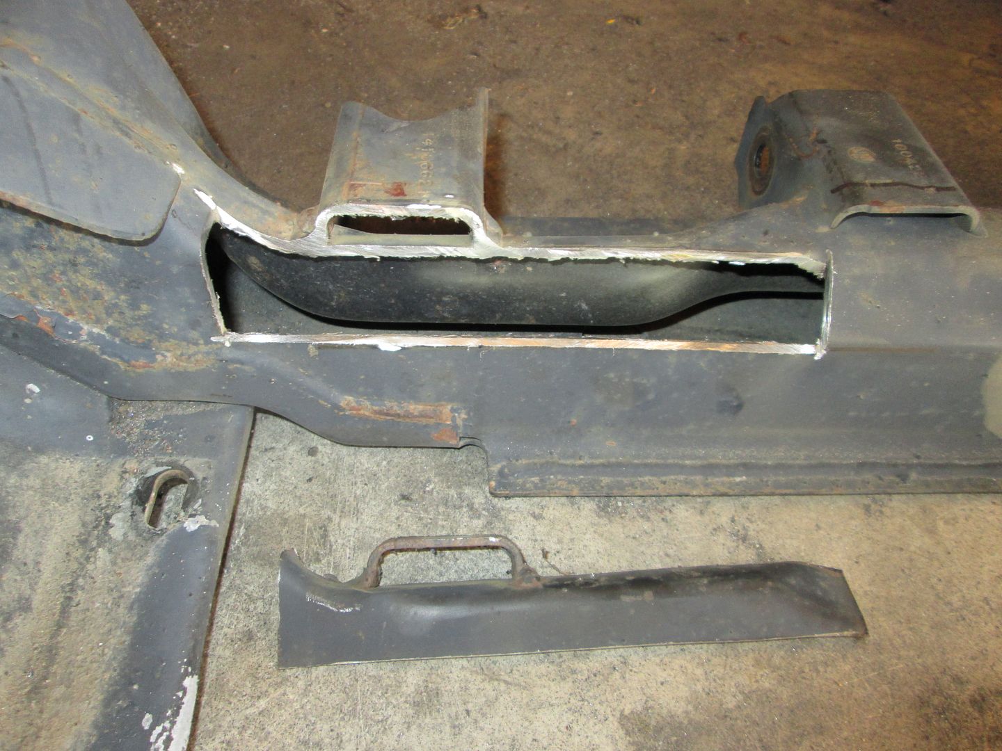
The next cradle mod was to the rear crossmember. It needs to have the flange removed to make room for the transmission. So I mark the general area to be removed:
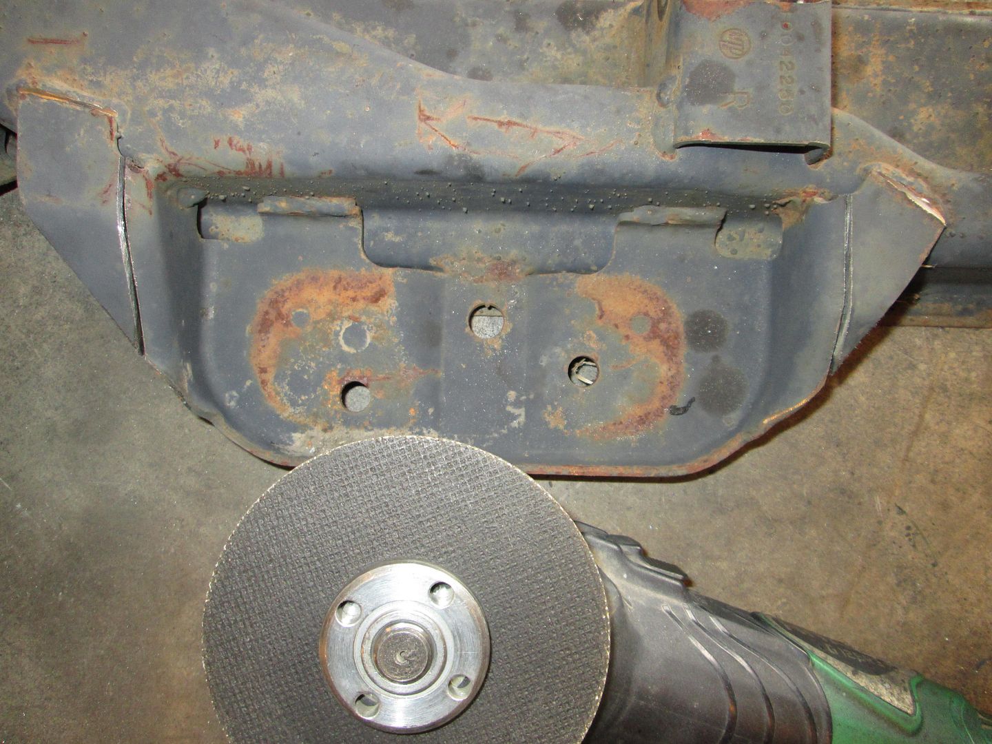
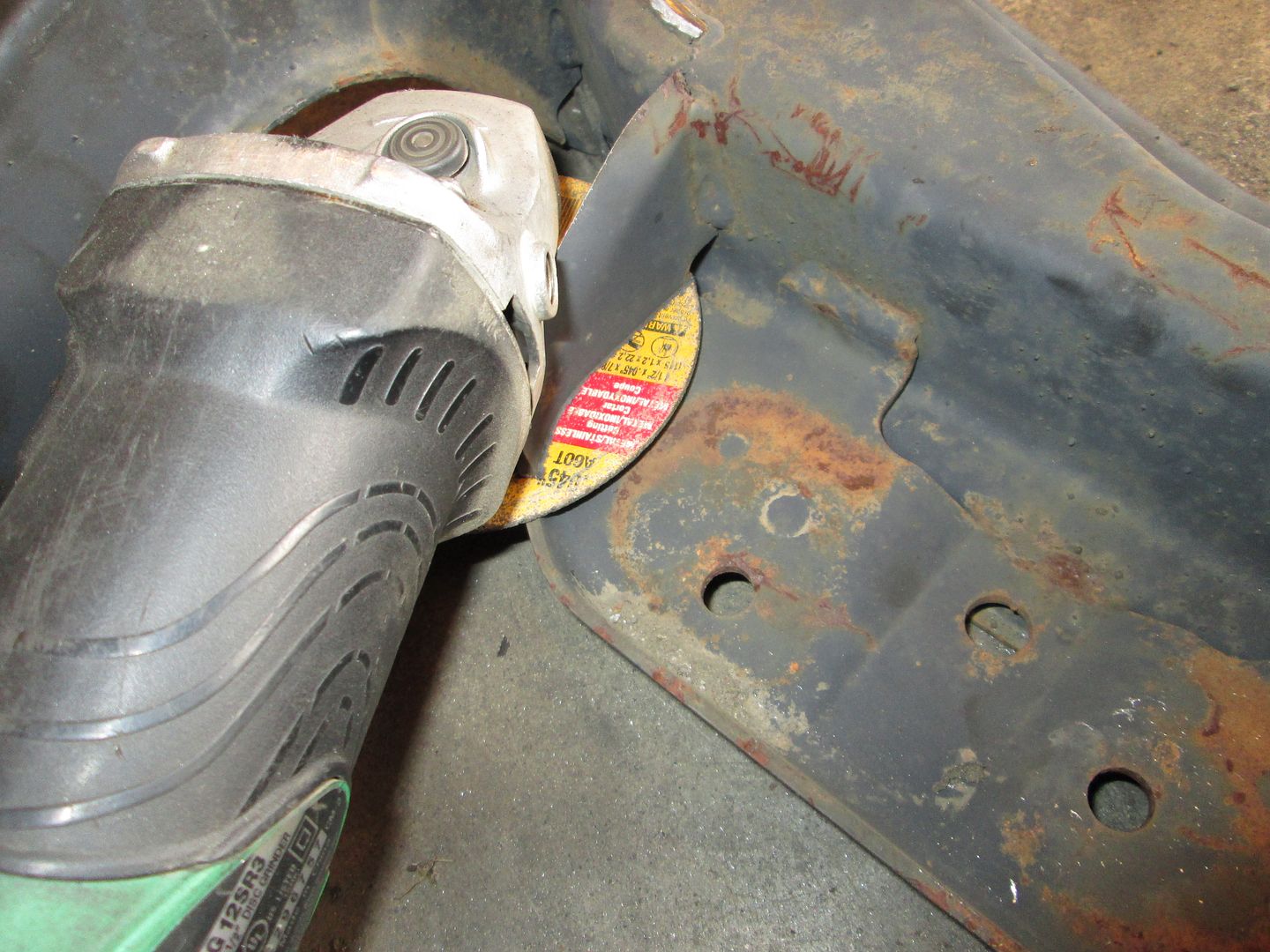
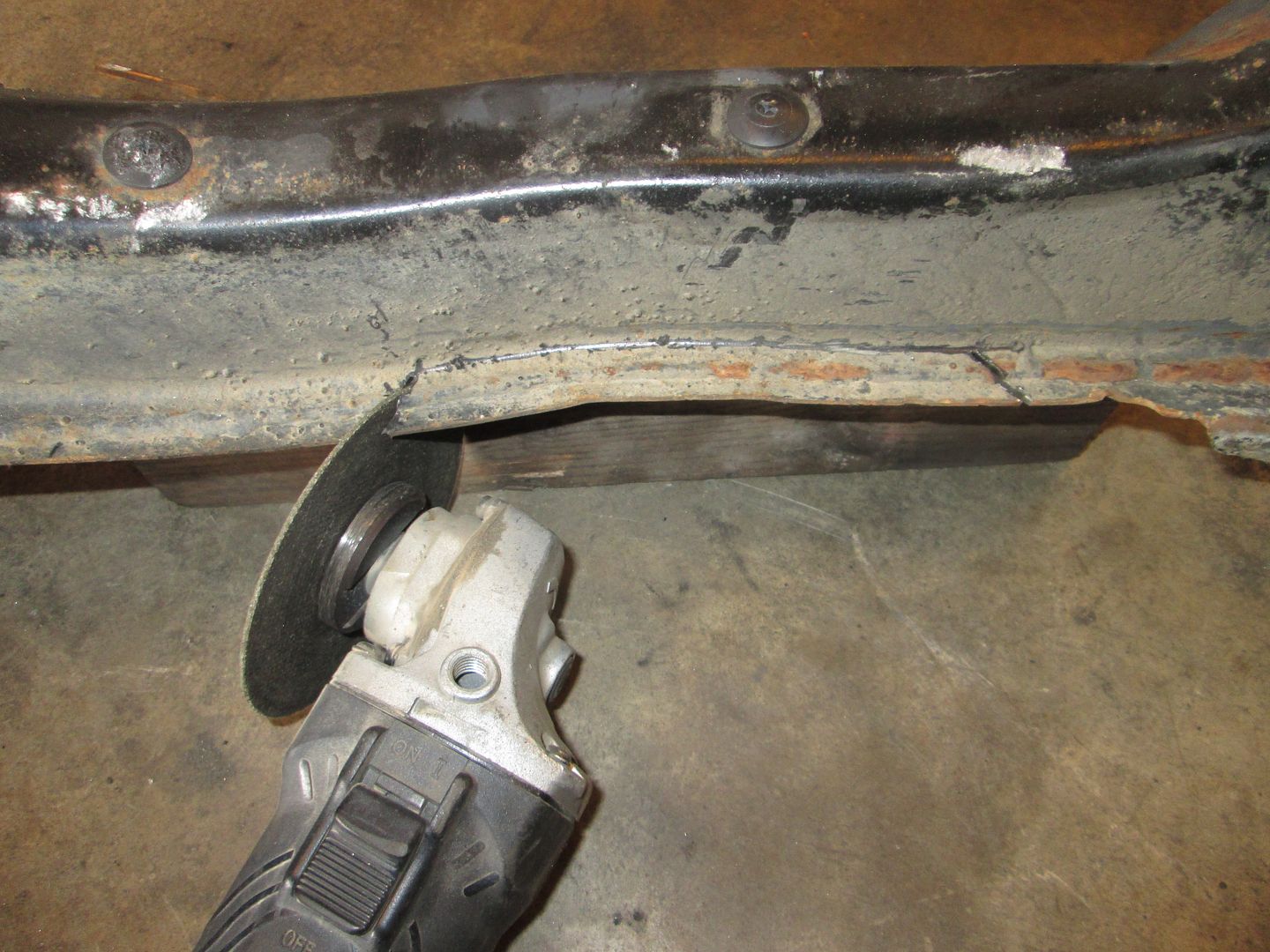
Using the grinder and cut off disk I make the angled cuts, flip it over and draw a line between the two, then cut most of the flange off:
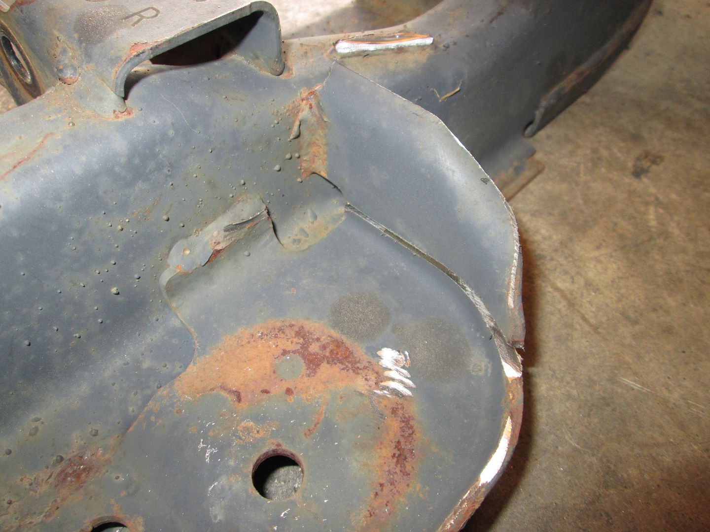
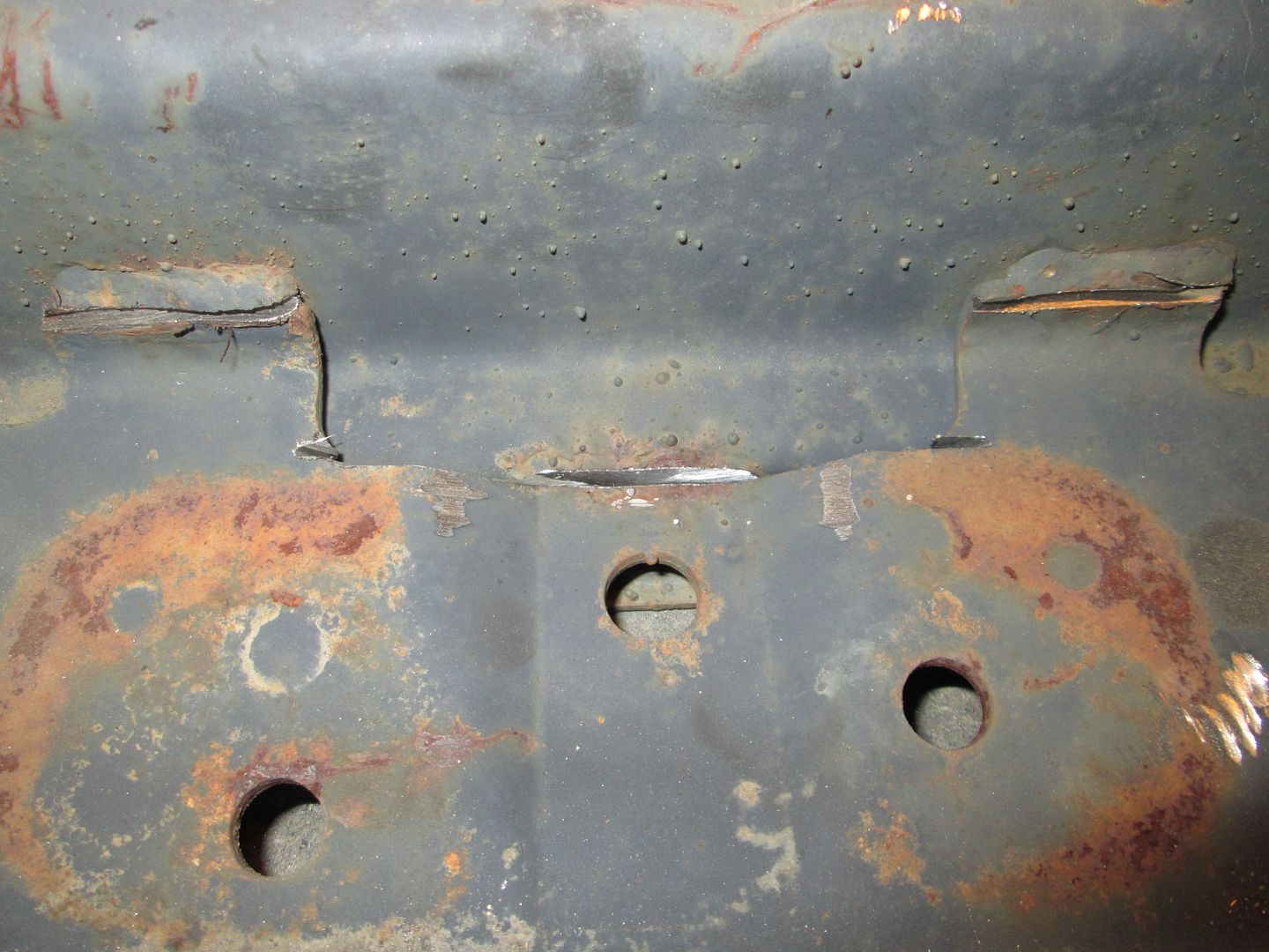
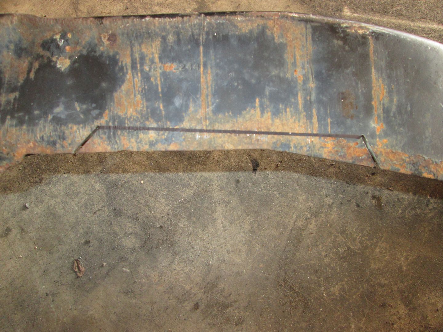
Switch to a 36 or 40 grit flapper disk and then grind down the remaining portion of the flange.
The area where the flange was removed will need to be welded, but I won't do that till I have the engine/transmission placement finalized.
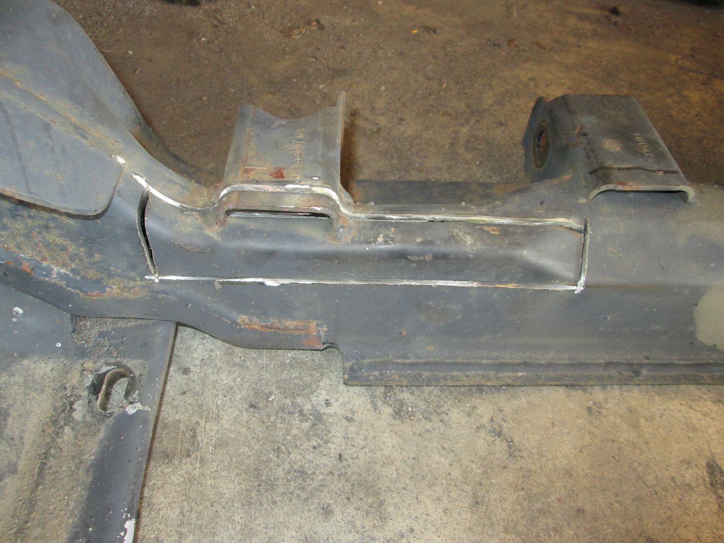
This next mod is to the driver side cradle rail. The front portion of it has a 45 degree angle to the top inside edge of the cradle and I want to extend it all the way across to maximize room for the transmission. Same deal, cut off wheel with hand held grinder...
Eventually I will weld in a new section of material (and then being my finicky self, grind the weld smooth so you will not be able to tell I made this mod).
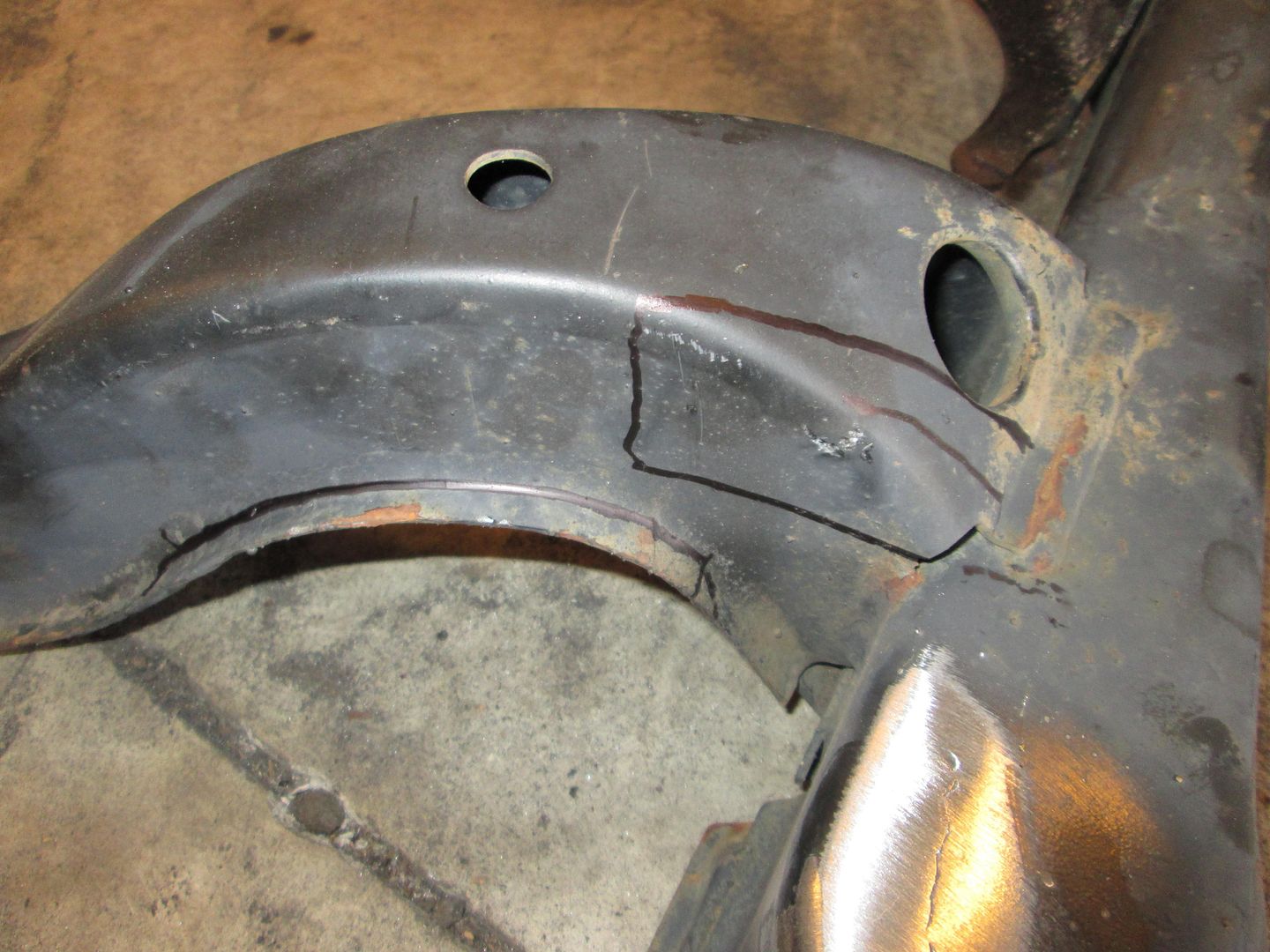
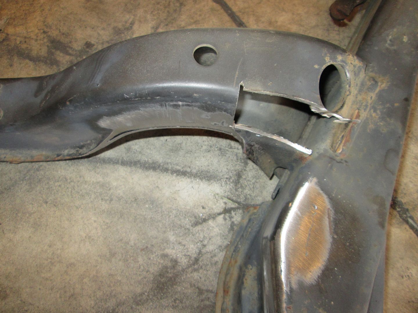
The last of the cradle mods is the front passenger side transition between the front crossmember and the side rail. The front crossmember tapers wider at this point and limits the engine being pushed forward. Once the final placement of the engine is determined, this mod might not be needed at all.
Same deal, mark cuts with sharpie, cutoff disk on hand grinder, then clean up the removed flange with the flapper disk and hand grinder:
I know I wrote down the engine placement/elevation for my LS4/F40, but I can't find it. So I jacked up the rear of the car and got some reference dimensions.
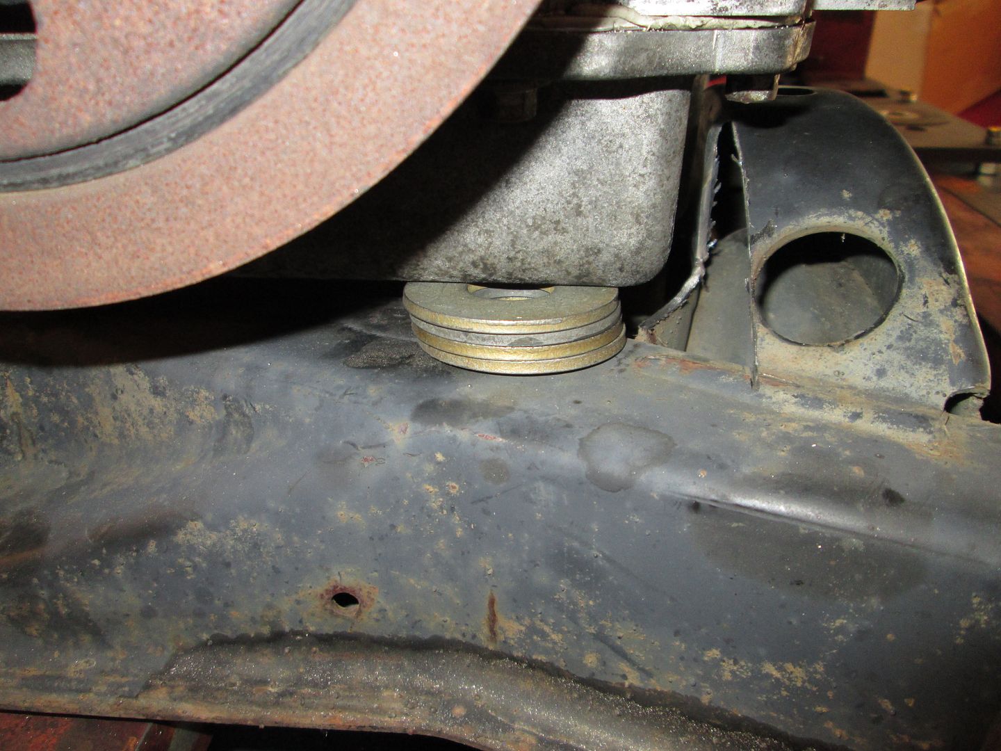
Let's start with crankshaft centerline elevation to the bottom of the cradle - just slightly higher and 8 5/8":
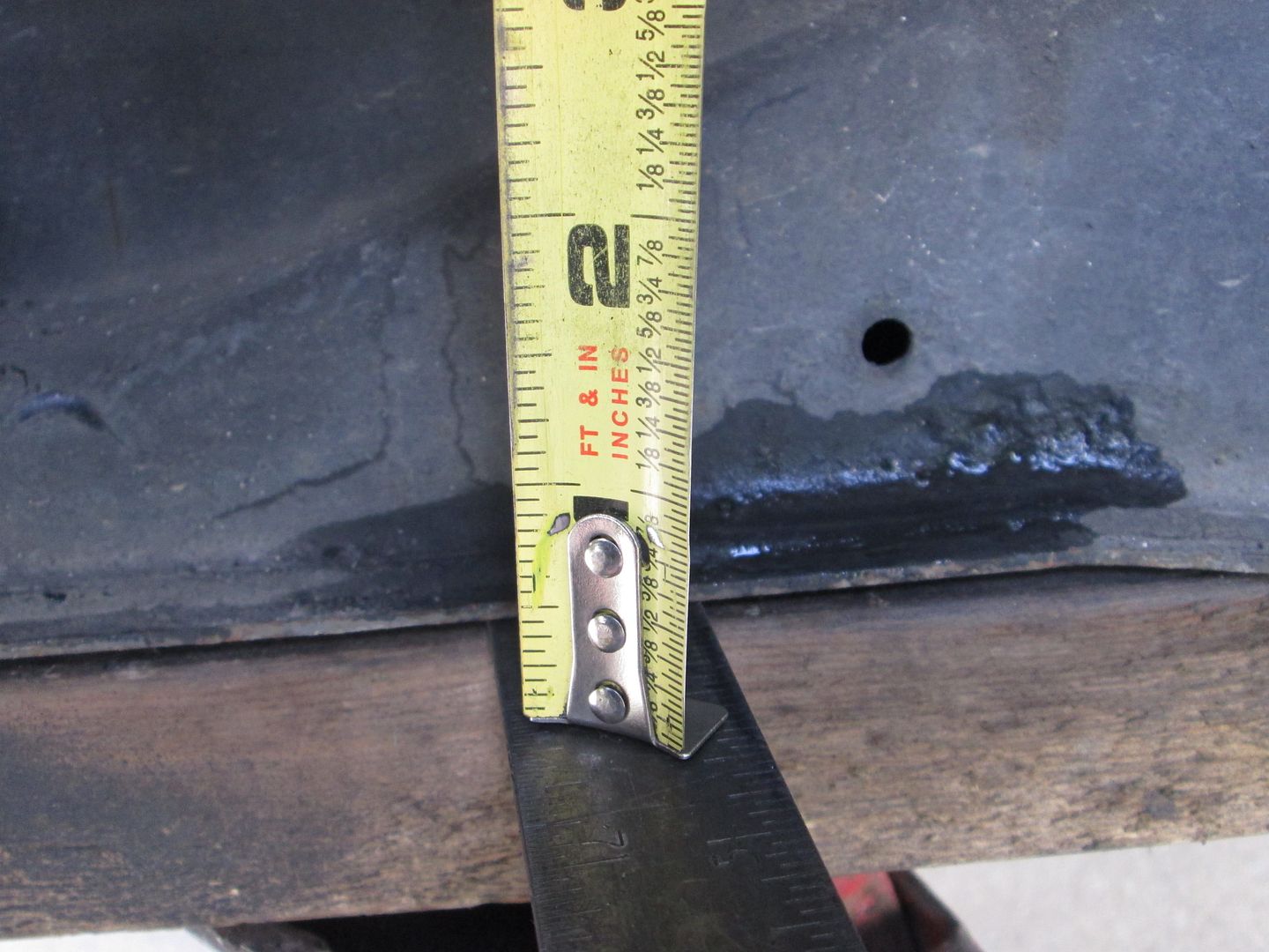
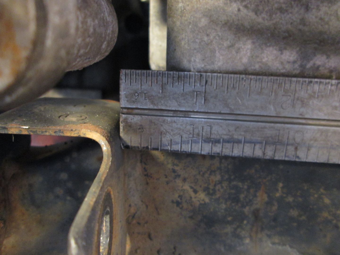
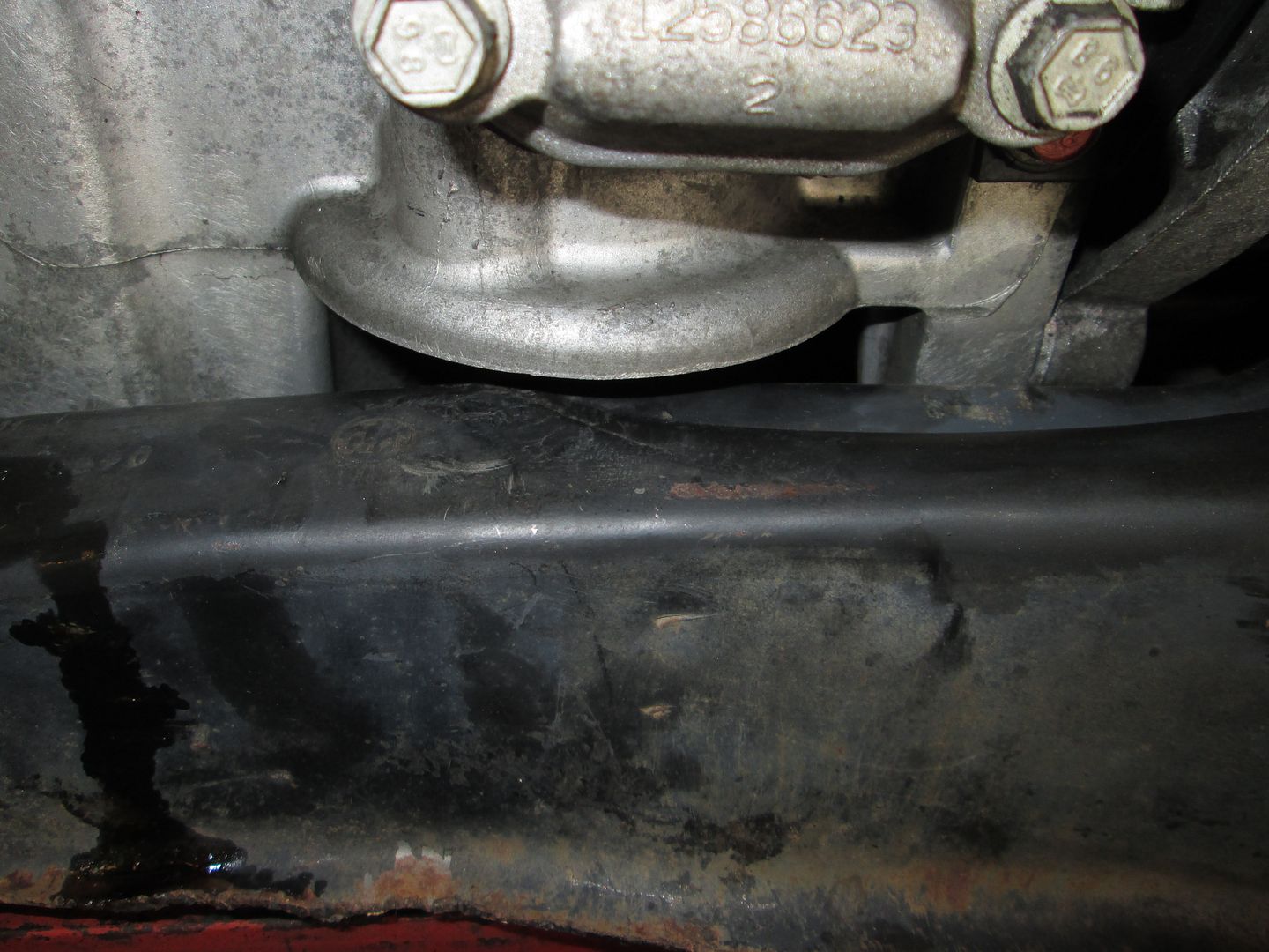
Another reference dimension is the space between the bottom of the oil pan and the top of the cradle rail (just under 11/16"):
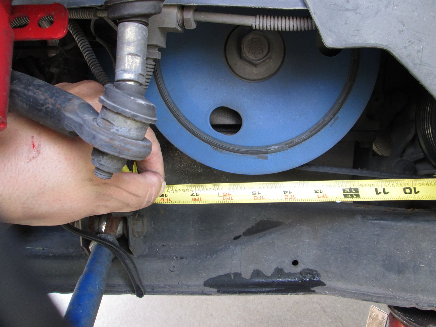
Now for the side to side placement, the edge of the balancer to the outer flange of the cradle rail is 11/16" - no pick, needed a 3rd hand to take one with the tape measure in place):
Another dimension is the inside of the DS cradle rail (not the flange edge) to the bellhousing face is 7 1/2":
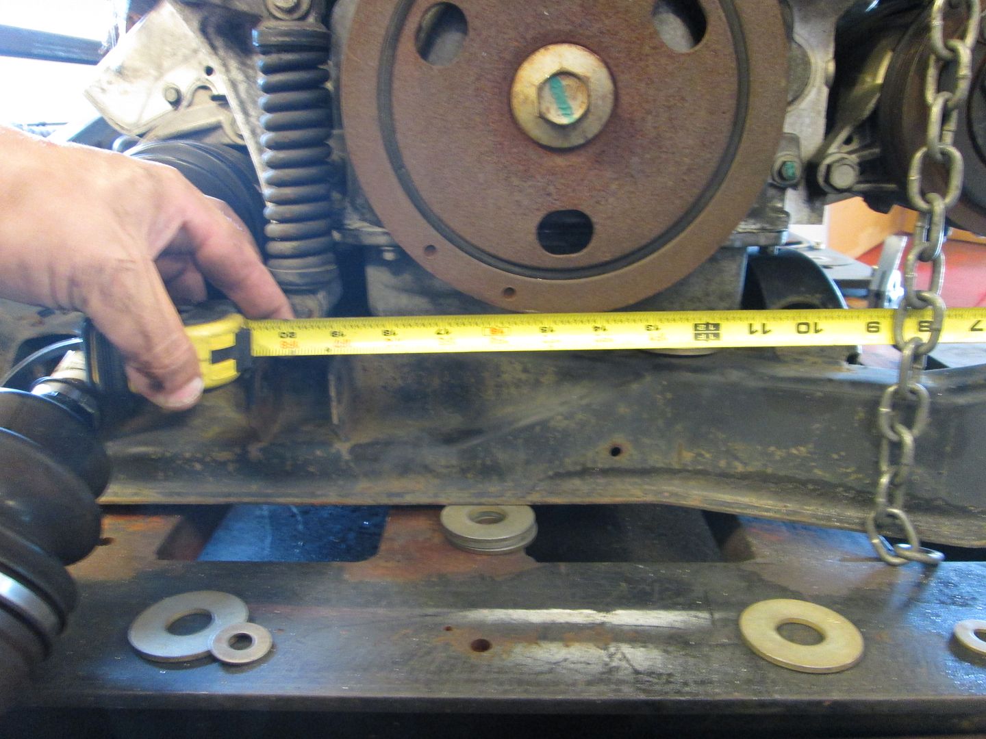
Last critical dimension is front to back placement. With I can't get a measurement from the crankshaft to the center of the front cradle bolt, but I can get it to the back side of the outer cradle bolt sleeve. Looks like its at 15 1/16":
Another reference point is there is 3/16" between the oil pan and the mount bracket for the forward lateral link.
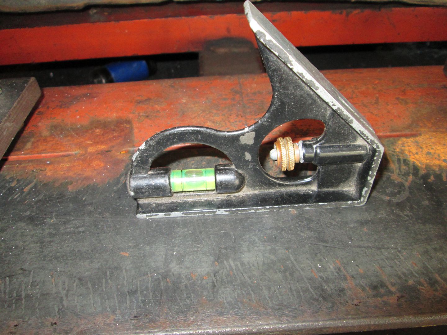
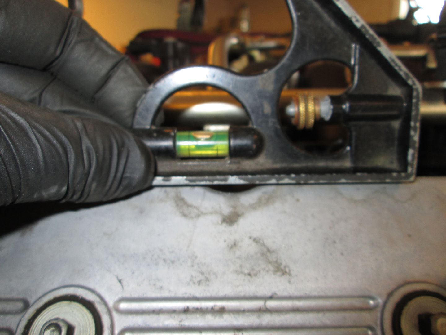
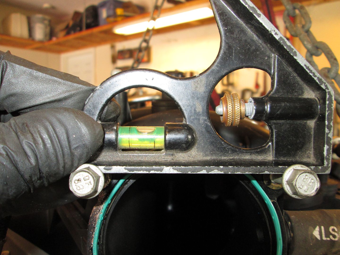
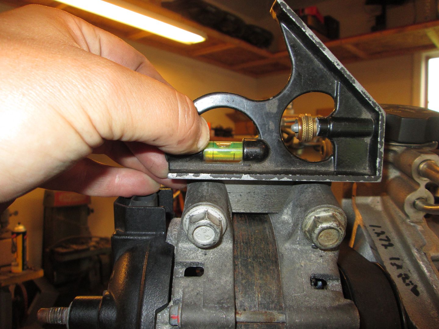
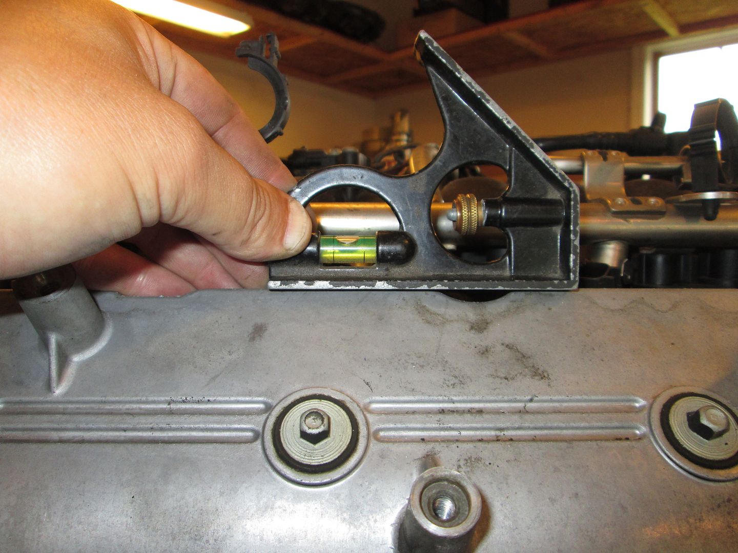
Now it was time to put the cradle back on the fixture along with the LS4/4T65e-hd and position it as far to the front and as far to the driver side as it would go and check for clearances and dimensions. The elevation was close, so I went ahead and leveled the drivetrain side to side: Fixture level:
Drivetrain level - side to side:
The front/back needs a little work, but I also want to remove the intake and measure this from the block:
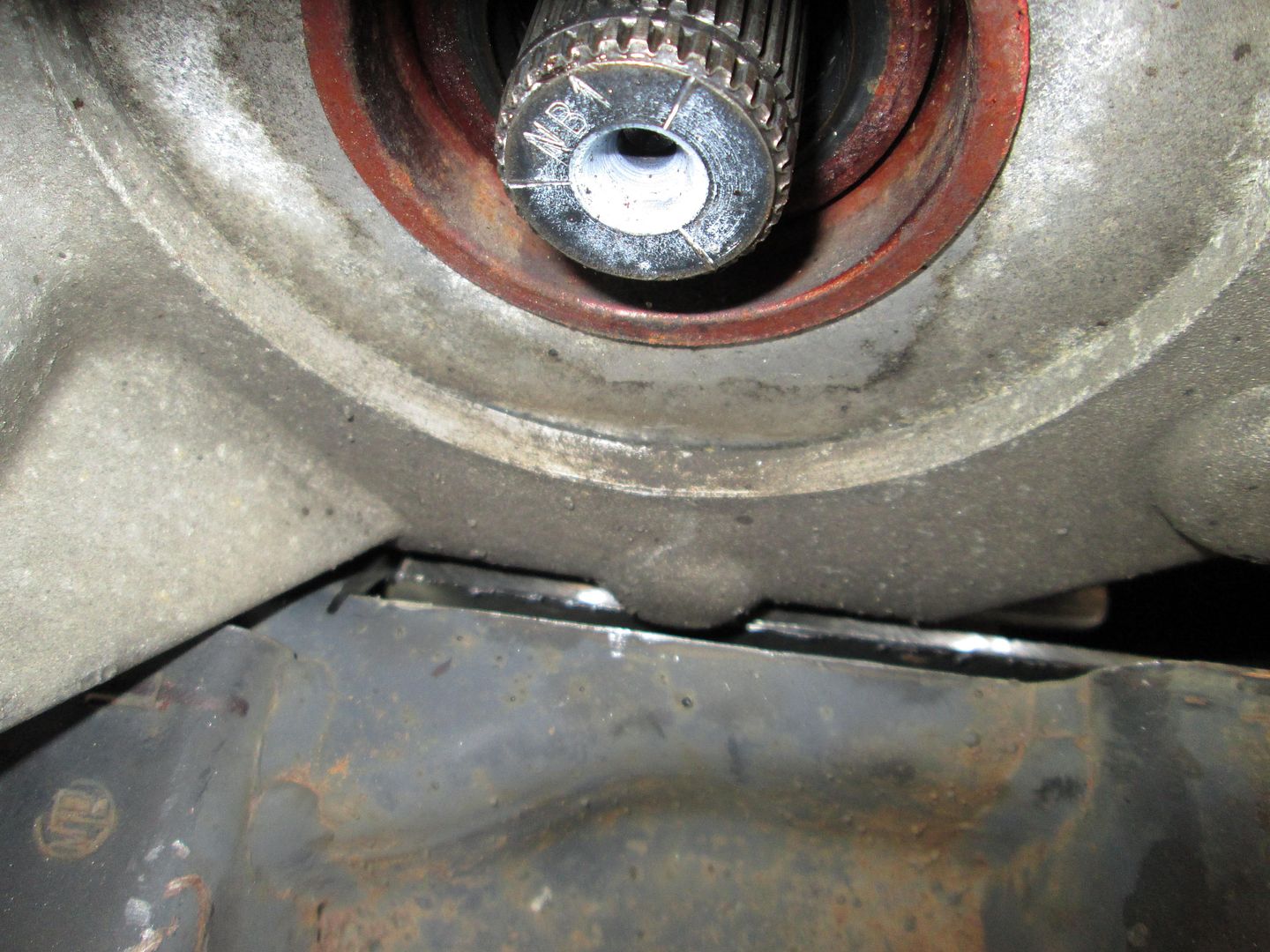
The notch on the front crossember didn't need to be as wide as I made it and might not even been needed with the final engine placement. This mockup is with the oil pan about 9/16" ahead of the lateral link bracket and it should be 3/16" to match my LS4/F40 car - so it will likely be moved 3/8" to the rear.:
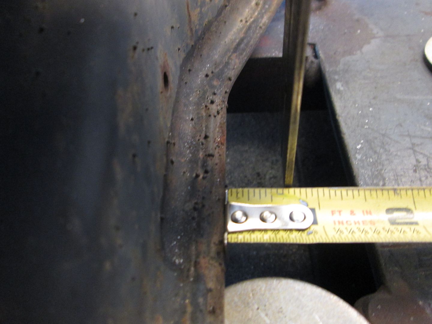
Here is the combined clearance front/rear... 11/16" at the corner of the canister. So my moving it back 3/8" the clearance will be very close to being matched between the two crossmembers. (I might even massage the crossmember with a hammer and punch to have a more uniform gap along the canister edge:
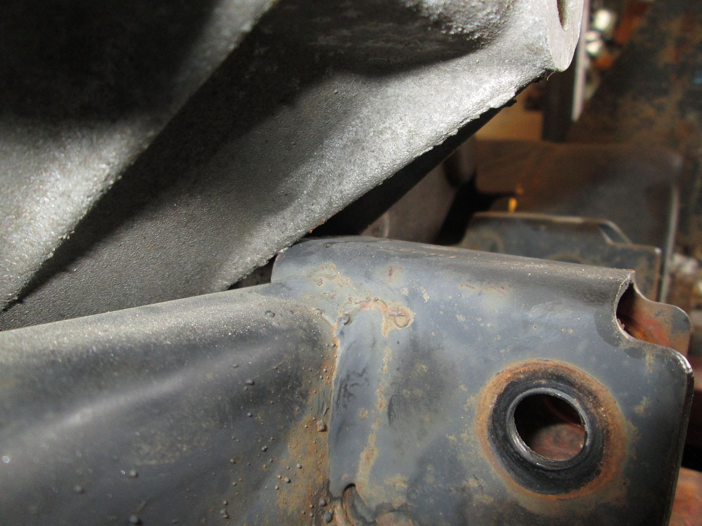
Here is the clearance (or lack there of) at the DS cradle rail. The side to side placement is at 5/8" vs 11/16" so the drivetrain should do to the PS by 1/16", but there will still be issues with clearance between the case and the lateral link bracket and the protruding boss on the transmission, so once the final position is determined, I will need to do some more clearance work in this area.
The last area was the oil filter. I want the cutout to be perfectly centered on the filter (anal like that), so I just removed the filter for now. Once the final engine placement is locked down, I will trace the filter boss and modify the cradle.
[This message has been edited by fieroguru (edited 08-10-2014).]
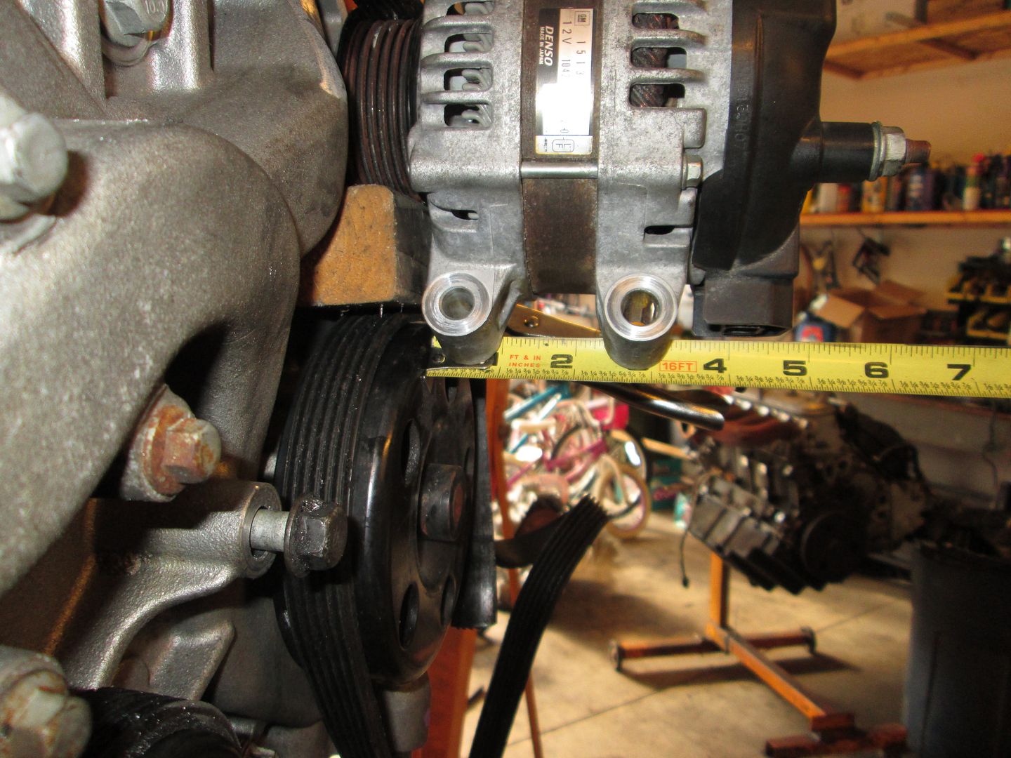
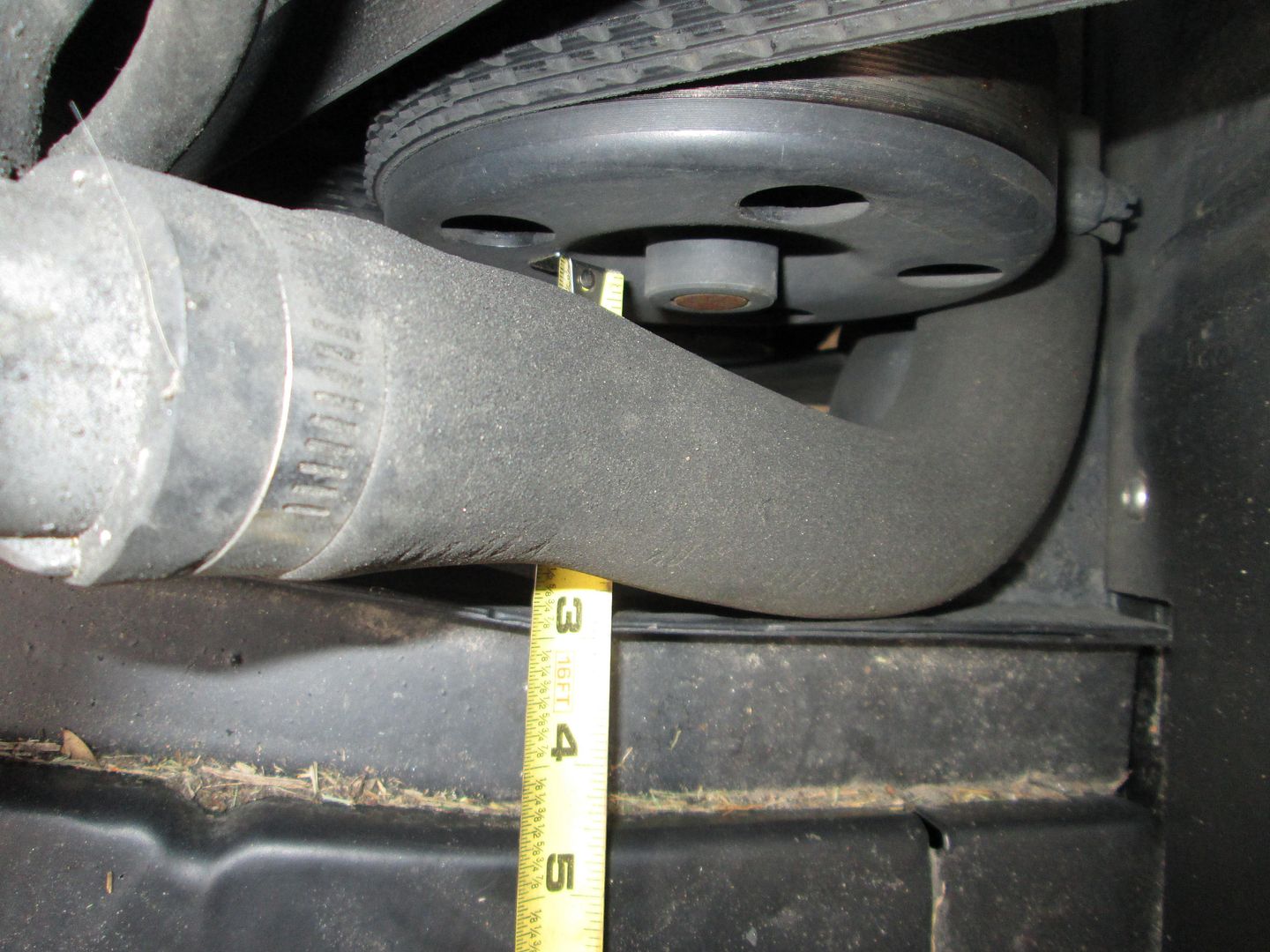
The last thing I did with the LS4/F40 car was to get some measurements from the engine to the firewall (fake panel about 3/8" closer to engine). Looks like the pulley is about 1 11/16" from the firewall:
From the bolt at the top of the head - 7 3/4":
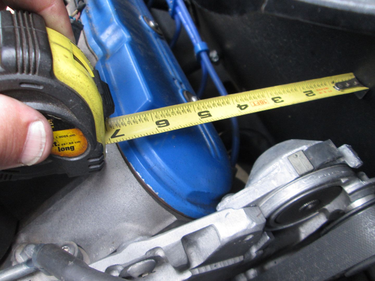
Then from the ridge at the top of the valve cover - 5 15/16":
I used those measurements to bend up some rod so I could get a visual of where the firewall would be:
Alternator to firewall clearance:
Marking the pump for the trim line (I want it to be parallel to the firewall) to make sure the engine had room to move around.
Some sample peices of tube that will be used to make the alternator bracket (a couple are too short - they are for a lateral link kit):
That's it for today! Monday/Tuesday of this week I have to cut the grass (about 4 hrs) and turn some 84-87 hubs for a customer order. By the time those are done, the longer bolts should be here and I can get back to the high mount alternator.
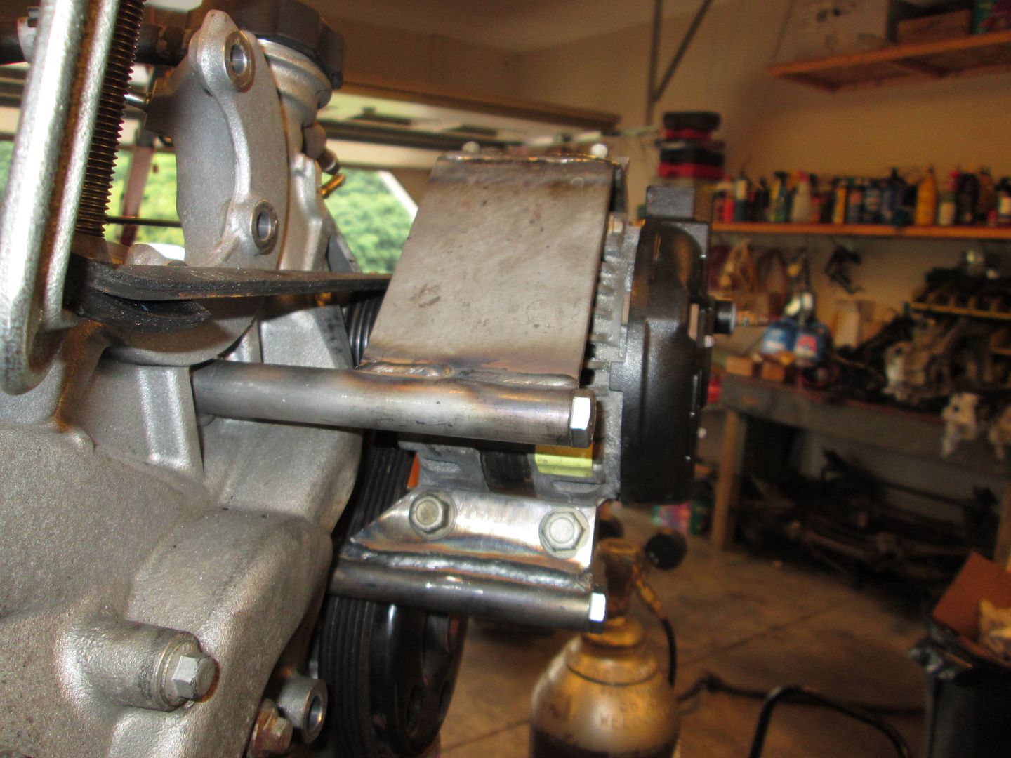
Finally back working on the alternator mount and I think the rough prototype is done.
I used some 3/4" OD / 3/8" ID steel tube and drilled it on the lathe for 10mm and cut it to length. Used the longer M10 bolts to secure the tubes to the water pump. Starting with the bottom, I measured the hole locations on the alternator and cut/drilled some 3/16" plate for the lower mounting tab. To keep the tab true to the tube for welding, I clamped both to a flat piece of steel and used spacers to position the tab on the tube. Once the lower tab was welded to the tube, I bolted the alternator to it, rotated it into position. By loosening one of the two lower bolts, I was able to level the alternator. Once it was in the right position, work started on the top mount. Same deal, but I used some 3/16" angle for the attachment point and a longer 3/16" plate to connect it to the tube. The 3/16" plate was welded to the tube just like the lower tab, then reinstalled and put into position. I covered the alternator and welded the seam between the two.
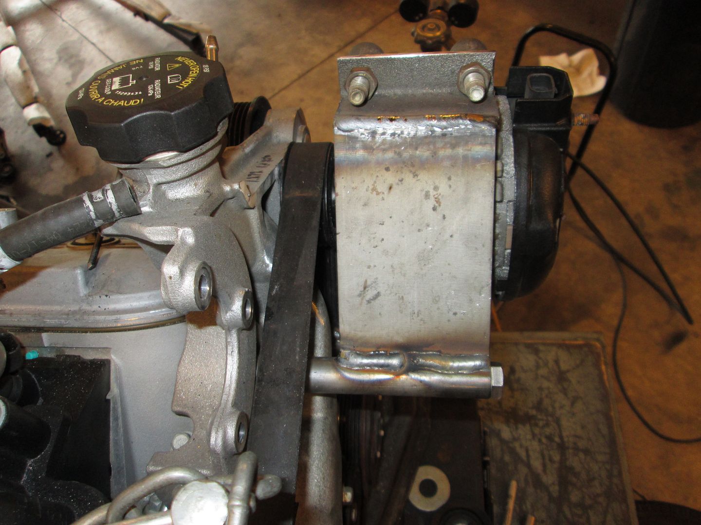
I need to get some allen head M10 bolts (probably stainless) for the upper mount. Hex head ones won't clear the angle and the bolts need to go into the alternator from the rear of the Fiero (no room for them to go in on the firewall side).
The belt was able to be installed with the alternator clamped into place. There is just enough room for the belt to fit between the alternator body and the water pump pulley (I did shim the pulley on the water pump a little more than 1/8" - which helped this clearance).
The pulley placement side to side is within .010" of where it was, so that should work:
The top of the alternator is level with the drivetrain:
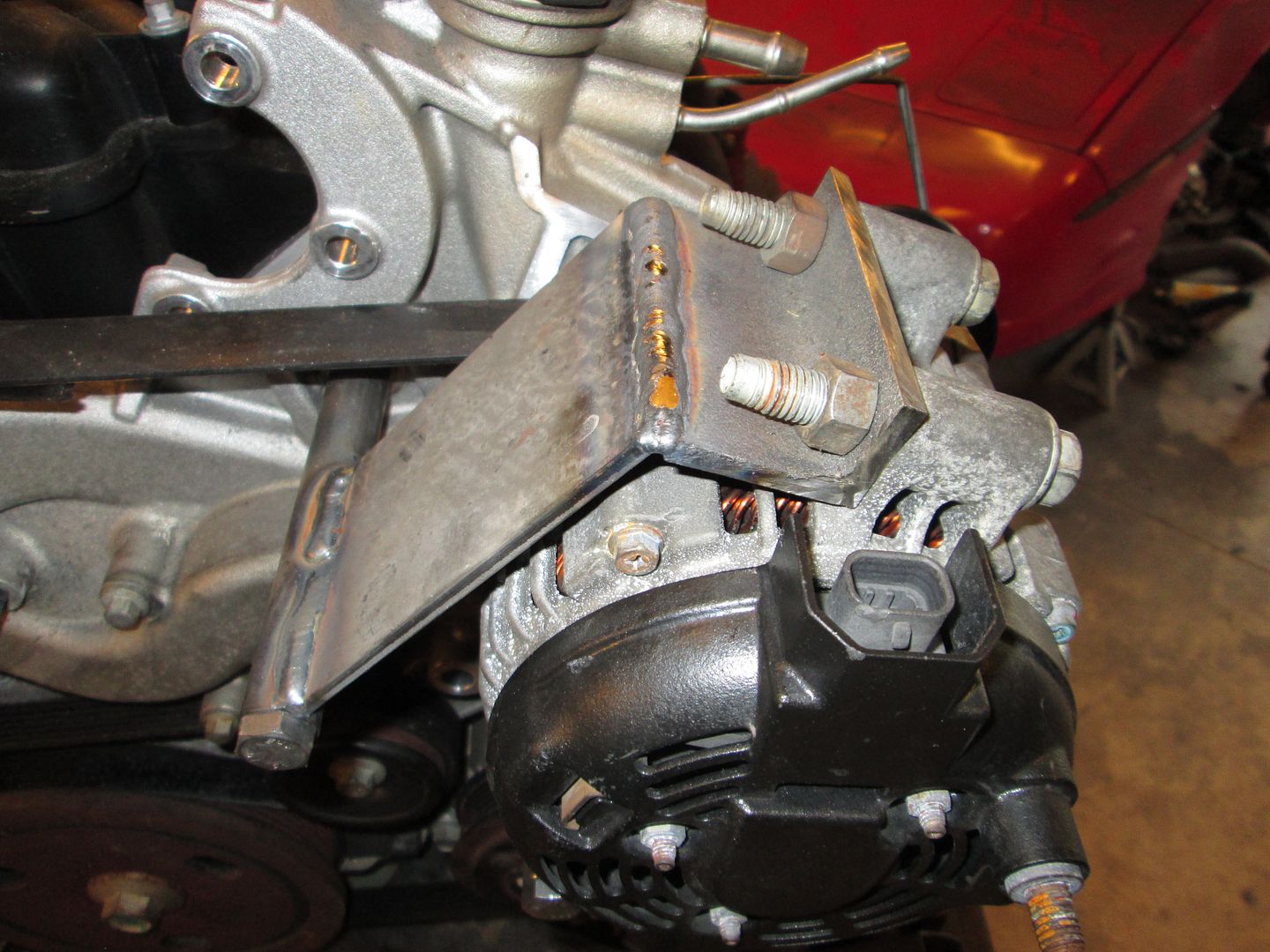
I also put a piece of flat steel across the backside of the alternator body and measured the distance from the valve covers to the piece of steel to make sure the edge of the alternator was parallel with the valve cover. It was... but I needed 3 hands to get a picture of the process... so I don't have one.
With just the two bolts and 3/4" tubes holding the alternator, I can't move it by pulling on it... so I don't think there is any need for additional bracing or complexity to the mount, but I will likely tweak the shapes of the tabs and plates to make them more visually appealing. They will be laser cut, so I can get a little fancy with the shape w/o adding much to the cost of the part.
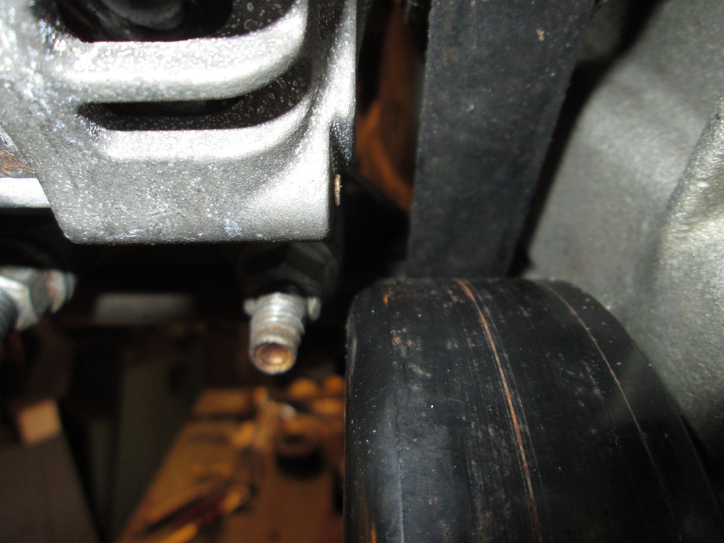
The next step is to remove the two M10 bolts from the water pump in the LS4/F40 car and see if I can line the alternator bracket up on them (firewall clearance check).
Interesting build! I was hoping that this swap would end up being do-able without welding, but obviously that isn't going to happen.
One measurement I'm interested in, once you have everything finalized... The rear face of the block, where the transaxle case bolts up. How far is it from the edge of the cradle or frame rail? Asking because I would be interested in trying this with the hydraulic TOB Getrag. Wondering how much fabrication will still be necessary with that installation. (Obviously if it's in a similar plane to the stock block face, all of the "front side" work will be similar.)
Thanks!
[This message has been edited by Raydar (edited 08-17-2014).]
Originally posted by Raydar: I was hoping that this swap would end up being do-able without welding, but obviously that isn't going to happen.
Welding is required for clearance work to the cradle, you can reduce it some by raising the drivetrain (but not the filter notch), but then you get into more complicated water pump mods (aluminum welding).
Since welding is required, I am probably going to take the easy way for mounts and make the tabs for the bushings weld to the cradle vs. making them bolt on. It will simplify the design and manufacturing quite a bit.
quote
Originally posted by Raydar: One measurement I'm interested in, once you have everything finalized... The rear face of the block, where the transaxle case bolts up. How far is it from the edge of the cradle or frame rail? Asking because I would be interested in trying this with the hydraulic TOB Getrag. Wondering how much fabrication will still be necessary with that installation. (Obviously if it's in a similar plane to the stock block face, all of the "front side" work will be similar.)
Stock 88 V6 has the bellhousing face at 7 1/8" from the inside lip of the rear cradle. The measurement I took on the LS4/F40 car (that I am trying to match with this swap) was 7 1/2 to the inner wall of the cradle (the lip sticks out 3/8" to 1/2" further, which would make it about 7" to 7 1/8"... pretty much right where the stock transmission is).
So in theory the engine side could stay the same, but you will need to rework your transmission mounts to match the front/back placement as well as elevation.
On the same 88 V6 car I got the 7 1/8" measurement from, 8 13/16" crankshaft centerline to bottom of cradle (vs. 8 11/16 for the LS4) and 15" from crankshaft centerline to center of front cradle bolt (vs. 15 1/16 to the edge of the cradle bolt sleeve - about 3/4" in diameter - so 15 7/16" to the center of the cradle bolt)
[This message has been edited by fieroguru (edited 08-17-2014).]
Thanks for showing me around your shop and projects the other evening Paul I received the stock fan and shroud to replace mine but now I am wondering if I might be better ditching the rear surge tank and going back to the stock unit as we discussed. I suppose the best course of action would be to see how it cools with the stock fan parts in place first. Highway cooling has always been fine. I meant to ask you about the way you did your valve covers, are you going to do these the same way you did the F40 swapped car? Further, would you consider doing them as a product for swaps like mine? They are so clean looking! Top work!
Will, it was a pleasure to meet you as well. For your car, I would leave the rear surge tank in place and see what happens. If the cooling issues continue, then that would be the next area to focus on.
With these two swaps, I am planning to keep the valve covers stock. While I really like the look of the modified ones, its a lot of work that kind of snowballs. Once the valve covers are done, you have to relocate the coils (fab up coil mount brackets), rework the harness for the new coil location, buy the parts for new plug wires, and assemble them... Just too much work and really out of scope for these two swaps - simple and economical.
As the cost of the aftermarket valve covers continue to come down, offering the smoothed valve covers isn't something I could do and be cost effective with... To do the valve cover mods, the inner splash shields have to be removed, valve covers cleaned really well, weld the base of about 3 or 4 of the bosses (they are dimples and will be holes if the tops are just cut off), reattach the splash guards, mill the bosses off as much as possible, switch to the flapper disk to remove more material and smooth them, follow up with a file to correct the contours, then use some filler to make them smooth.


 I received the stock fan and shroud to replace mine but now I am wondering if I might be better ditching the rear surge tank and going back to the stock unit as we discussed. I suppose the best course of action would be to see how it cools with the stock fan parts in place first. Highway cooling has always been fine. I meant to ask you about the way you did your valve covers, are you going to do these the same way you did the F40 swapped car? Further, would you consider doing them as a product for swaps like mine? They are so clean looking! Top work!
 you keep this up and you're fired.


