Just by looking, I can tell that this next photo was taken on the back straight/drag strip. Notice the headlight door open? It was a real shock the first time I got onto that straight with some speed. Bang! Up popped the headlights maybe 3/4 of the way down the straight away. We got used to it, but I'm sure it startled some other drivers. You could tell how well you were progressing by how soon the headlight doors popped up after entering the straight.
First off, I gotta say that this is the most informative and enjoyable thread ever at PFF (and I've been here almost from day one). It's well written and has lots of photos and links. Great stuff!
Now my question in regards to the quoted photo and post above... To alleviate pent-up air pressure up front, you made various modifications as outlined HERE. Judging from the photo and description above, it doesn't seem to be fulfilling that objective. I'm really surprised you didn't simply put an extraction vent in the hood immediately behind the radiator. You must've had a reason for that. What was it?
First, thanks for the kind comments. I'm hoping someone finds it entertaining.
Wow, I cannot believe that I failed to mention the hood scoop we installed. I'm guessing because it was almost a year after purchasing a scoop fro Paul "Tha Driver" that we actually installed it. http://angelonearth.net/customfiberglass/
Paul modified his stock scoop offering, deepening the opening by (I believe) some 3 inches. Maybe not as pretty as the stock street version, but we hoped for better functionality.
The photos indicate that the first time we ran it was at Sears Point. But the engine burning down kind of overshadowed that part of the build story.
We actually had the scoop installed at Buttonwillow where the headlight flaps came up on us.
With the engine temps reaching 235 at Buttonwillow, and the flaps indicated that we didn't have enough control over the air, we reworked a lot of shrouding before the next race. I'll share some pictures once I get through the suspension. But I think we would have been much worse off had we not run with his scoop.
Thanks again for the kind words.
[This message has been edited by DonP (edited 10-13-2014).]
Hi KurtAKX, I cannot say for sure which bender Rich used. I think he used his air over hydraulic Mitler Bros bender with an appropriate shoe. https://www.fiero.nl/forum/F...L/090867-3.html#p103 But he also has a smaller manual bender that he may have used for this small tubing. He's out of town at the moment, but I'll follow up when he returns.
First, thanks for the kind comments. I'm hoping someone finds it entertaining.
...Thanks again for the kind words.
Heck... thank you for this wonderful thread. It's allowing a lot of us here to do vicariously what we're not able to do with our Fieros (for a variety of reasons) in real life. I look very forward to all your updates.
quote
Originally posted by DonP:
We actually had the scoop installed at Buttonwillow where the headlight flaps came up on us.
With the engine temps reaching 235 at Buttonwillow, and the flaps indicated that we didn't have enough control over the air, we reworked a lot of shrouding before the next race. I'll share some pictures once I get through the suspension. But I think we would have been much worse off had we not run with his scoop.
Ah, I didn't realize you had installed that vent. You must've had to modify the front of the tub to get the air channeled that far back on the hood. I wonder if there's any possibility that the high pressure area in front of the windshield is interfering with the flow of air out of the vent where you have it currently positioned? Did you feel there was an advantage of some sort to have located it there instead of further forward in front of the tub (and behind the rad)?
Ah, I didn't realize you had installed that vent. You must've had to modify the front of the tub to get the air channeled that far back on the hood. I wonder if there's any possibility that the high pressure area in front of the windshield is interfering with the flow of air out of the vent where you have it currently positioned? Did you feel there was an advantage of some sort to have located it there instead of further forward in front of the tub (and behind the rad)?
The photo above really doesn't show the air path to the radiator. Here's a photo, taken later after we added additional shrouding, that shows the direct path. There was no post radiator shroud during our Buttonwillow adventure.
We did, when we installed the vent, cut the front tub bulkhead. Our thought was to create as direct a path as possible, given that the natural airflow is down then up. Had we been closer, and saved the tub, I think we wold have lost some efficiency. I think.
The upper control arm construction pretty much mimicked that of the lower arms. Two things were different. First, we widened the distance between the inner pivot points slightly as we anticipated wanting needing more room for the coil-overs to pass through. And we added a bit of tilt to the upper ball joint sleeves to compensate for increased angle in the arm.
With the swap out of the upper and lower ball joints for heavier duty units, we had to deal with making them fit the Fiero spindles. It turns out there are only a couple common tapers used on ball joints. But different vehicles fall at different points on that taper. Rich just happens to own the appropriate taper reamer, so it's just a matter of enlarging the hole until everything fits. Carefully.
So, at this point we had the major components built and it was time to start seeing how to make it all work together.
I have a question to ask. This last weekend an engine builder friend stated that if we converted to a dual exhaust on the Series II 3800 SC we are running, we should pick up 18 ft./lb. of torque. Anyone have experience with such a change and perhaps data on what the results were?
It looks like you're going at the build the right way! Looking at the car on that strait with headlight door up, I can't help but notice how high the car is ridding. My son also races in chump -east coast- and has the most wins -his MR2 team (Bio-hazard wins about 60% of their races) He uses a DIY -not on car in photo yet- plywood front air dam to help keep the front down; you may want to look into, remember it's about going fast, looking great don't help.
It looks like you're going at the build the right way! Looking at the car on that strait with headlight door up, I can't help but notice how high the car is ridding. My son also races in chump -east coast- and has the most wins -his MR2 team (Bio-hazard wins about 60% of their races) He uses a DIY -not on car in photo yet- plywood front air dam to help keep the front down; you may want to look into, remember it's about going fast, looking great don't help.
Thanks for the comment.
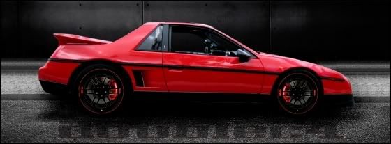
You'll like what you see in a more current photo of the car. But I can't get that far ahead in the story. But plywood can be very useful.
That's the car as it looks today. With an area 51 theme. I'm trying to recall where I saw some stuff on your build. Here on the forum?
We've already signed up for the next Miller Motorsport Park LeMons race, October 3-4, 2015.
Don
Yeah... I posted a short build write up after the Miller race. Will do another after the car is running again.
I spoke to one of your guys several times during the Miller weekend. He came over asking if we had any spare lug nuts on one occasion. I just wish we could have finished the race. Should have the 2.8 liter in the car next week. It's been slow going since Im the sole person working on it.
I've got my car signed up for Miller next year as well. Same number. Im also mulling over obtaining another car for that race as well. Either way, Look forward to racing with you all again.
The final component that we needed to fabricate prior to actually assembling the front cradle was the shock package. I say package because, like the rear DIY coilovers, we elected to build a DIY coilover-like affair. The rules pretty much made it a non-starter to buy an off the shelf coilover set up. Trust me, that would have been far easier and the direction we would have gone had we been allowed to. So we had to design something that would meet our goals of having an adjustable ride height as well as accommodate a larger selection of springs. As opposed to a real coil-over where the shock body incorporates an actual spring perch, what we did was have a stock shock mounted inside the spring perches.
Fortunately, when Rich had purchased the box full of parts that had supplied our rear coilover components, he had also got enough other parts in the lot to make our front setup. The only thing we still had to purchase was one nut/spring thingy. The gold part in the photos below. We got enough of the threaded tubes.
If you recall, Rich had a chance to go to a racers swap meet, where folks sell their used or surplus stuff to buy other folks used or surplus stuff. Nobody ever seems to be able to clean out their garage, but just swap the contents. Or at least that's how it usually works with us. Anyway, Rich hit on of the sellers with ten minutes left in the swap meet. The seller didn't want to take it home, so he got a box full of coilover related stuff for next to nothing.
Because we couldn't use actual coilover shocks, we used the KYB shocks for an '88 Fiero. These are stock replacements.
Rich made two plates that would act as the spring perch. One for the top of the shock package, the other for the bottom.
The bottom perch would actually have the threaded tube resting on it, with the shock passing through. So the bottom perch for the threaded tube received a second concentric hole for the shock body to pass through.
Obviously there would need to be a mechanism to hold the threaded sleeve centered on the lower perch. Just sitting on the perch like this wouldn't do it. In the background you can see the top shock/spring mount plates. The stud on top of the shocks pass through tis plate as well as those rubber grommet/washers that come with the shock.
So Rich cut a piece of exhaust tube that would fit inside the threaded tube but fit outside of the shock body.
We had to smooth out a seam inside of the threaded tube for the locating pipe to slide freely.
The top shock mount also had a piece of exhaust pipe welded on to center the spring. This pipe did not pass through the plate because the top shock mount stud needed an attachment point.
Rich made a couple tabs that would accent a pass through bolt to mount the top plate to our yet to be built chassis pick-up points.
On the bottom perch, Rich made similar mounts, but a bit wider to accommodate the lower shock mount. This would allow the whole assemble to move with the suspension.
Once we got this far, we could start to see how everything would come together.
Checkout the link below and the plywood front air damn, rear wing, and other mods, like the pushed-out front fenders to lower wheel well pressure. It's kind of like the lyrics from that old song: She ent pretty, but she sure can cook In this case she ent pretty, but she sure is fast
Add a front air damn and rear wing and with your other mods, you should do good. BTW to keep cost down and thus penalty laps, the rear wing is also wood, built up with ribs, spars, and covered etc etc. He now races in chump only, the competition is better. Good luck
Looking back at the last couple pictures I posted, one problem jumps out. The shock package is very unlikely to be able to pass through the stock spring pocket of the front cradle. I'll go a step further and say, there was no way it would work.
As you might suspect by now, we aren't too shy about making modifications as needed. Or as we want to. The obvious solution was to remove a portion of the cradle that included a portion of the spring bucket. And so we removed the shock tower/support as well.
So, having made that decision and modification, we started to build the front cradle. Knowing that it's important to have a proper, precision surface table to do this type of work, we of course headed to Lowes. We carefully selected their finest 3/4" plywood and wrapped it with butcher paper for proper marking. We set up and leveled Rich's jig on some adjustable saw horses. On top of this we placed a frame to support the plywood and presto! we had a surface table. This was the same frame he used on building his IMCA Modified car.
We knew the ride height that we wanted the front cradle to sit at. So we were able to put together a couple metal pieces to support the frame the desired height off the surface. Obviously we took as much care to keep everything square and level as possible.
Rich had some very specific goals for the reworked front end; > 3 ½ degrees negative static camber > Under ¾ degree of loss in camber in 10 degrees of chassis roll in cornering. Most front suspensions create negative camber when you jack up the lower A frame. But when you add body roll it creates a loss of camber and that is one of the reason static camber is added in race cars. > No change in caster as the suspension goes through bump and rebound > 6 degrees of caster > 4” roll center > 10 percent anti dive > Less than .030 bumpsteer > Expanded selection of spring rates
My eyes kind of glazed over, and I went back to sweeping the floors.
The process went something like this. We set the cradle at the desired ride height. we then attached the lower control arms with the proper spacer to locate the arms front to rear.
Having the lower arms attached, we could determine a reference line between the two lower ball joint centers. This line gave us something to measure all other pick up points fore and aft.
We also located the centerline of the cradle. This center line, drawn on the surface table/plywood gave us ability to locate any other point left and right.
The fact that we now had some reference lines, meant that we could start to lay out the suspension. Rich and I had purchased a suspension design program from William C. Mitchell software ( http://www.mitchellsoftware.com/prod01.htm )several years ago. So the plan was to mock up the suspension with the parts we had decided to use, measure everything, input into the program and see what the results were. From there we could move points in space and see what the resulting changes were. And presto, we would have a new suspension with better geometry.
Yeah, right. Like it would be that easy.
Anyway, the next step was to add the front spindle upright to the mix.
With the upright attached, it becomes possible to determine the height of the lower ball joint. Simply put, if you know the diameter of your wheel/tire combination, you can determine how high off the ground plane the center of the spindle (in this case hub) will be. If you raise the hub until it's at the ride height, the lower ball joint and control arm can be determined. They are all bolted together. One moves they all do. We actually took measurements on another Fiero to try to determine how much the tire would be compressed when on the car. So we added in a fudge factor to the center of the hub to allow for that distortion of the tire.
Once the height of the lower ball joint has been determined, we used a small screw jack to position the arm on the Z axis, how high the arm is off the floor plane.
You may notice at the very bottom of the picture, just in front of the support under the screw jack, we have that reference line that was drawn from ball joint to ball joint.
With the ball joint positioned on all three axis, Rich could start to position the other components. At this time we tried to fine tune the actual ride height of the cradle. Because the data was already published on locating the center pivot point on those fancy MOOG ball joints, we could easily find the height of the actual pivot point.
Hopefully, the pivot point on the inner heims would be very close to the same height, meaning that the lower control arm was level. That was the ideal.
These are somewhat out of sequence, but we took a look at how the spindles would look at the static camber we were after. Ignore the readings, this was staged for photos.
Once the hub is located, with the static camber desired, we could start to look at other components such as the upper control arm.
Now it started to get even more complicated. We needed to fix what we could in place while allowing the freedom to manipulate components that could not yet be nailed down. Try telling an assistant to "hold this upright right here, without moving at all while I swing these other components around to see what happens. And don't move for three hours." Not likely. It actually took some time to figure out how to make this all work. We knew where the inner pivot points on the lower control arm HAD to be. They were fixed. We knew where the lower ball joints HAD to be. That was fixed. So the lower control arm was fixed and essentially immobile. We knew the amount of camber we wanted on the control arm. So that determined where, left to right or in and out the upper ball joint would be. So now, if we could position the spindle to the desired camber and slope backward which gives us the caster we could know exactly where the upper ball joint resided.
The solution came by welding small braces between the fixed lower control arms and the nut at the bottom of the upper ball joint while the caster and camber were where we wanted them.
Now we were getting somewhere. The inner pivots of the upper control arms were still floating and had to be locked down. But all the other points were fixed on all three axis. I wish I could say that having everything else fixed made the mounting of the inner upper control arms obvious. It did not.
It was pretty obvious that we would not be mounting the upper control arms in the stock manner. After all, we had eliminated the control arm shaft as well as replaced the bushings with heim joints. And we had actually removed the stock mounting pad from the cradle. Locating the upper arm to cradle pick up points was our biggest challenge. the location of these points would affect every one of our target alignment goals. I personally think that I had a reasonable understanding of how all this stuff was interrelated. I understood why unequal length control arms are used - to allow for camber gain or at least minimize any loss. But how do you determine or design in how much down angle is needed from the upper ball joint to the inner pivots of the upper control arm. 'Cause the angle of the control arm(s) also affect the location of the roll center.
If you lower the roll center by changing the angles on the arms, you can change the distance (mostly we are talking vertically) between the roll center and center of gravity. If the distance increases, you increase body roll. So what are the desired results we want? Rich set the goal of a roll center 4" off the ground.
But wait a minute, doesn't tilting the control arm front to back change the plane or line in the upper image that helps define the roll center? Yup. And it gets more complicated from there.
I'm not going to even try to define any of the steering/suspension geometry stuff beyond what I just wrote. First of all, I'm not an expert and will just open the door for a discussion I'm ill equipped to participate in. There are guys here on the forum that seem to eat and breath this stuff. Heck, I never even heard of Pro Dive outside this forum!
So back to the stuff I can talk about.
Realizing that there was no way to just hold the upper control arm in place Rich built a simple angle iron mounting plate that we could secure where we wished with clamps or weld tacks.
To the best of my knowledge, Elves came in during the middle of the night and tacked the upper control arm brackets at what would approximate the stock mounting positions. We now had the task to measure, as exactly as we could, all the suspension pick up points and pivots in 3d space. Let's see if I remember everything we needed to measure. Each Lower control arm pick-up on the x, y and z axis. Lower ball joint center/pivot point on all three axis. Spindle center at ride height. Upper ball joint center/pivot on all three axis. Inner tie-rod pivot point , all three axis. Outer tie-rod pivot point on all three axis.
Ever try to determine the center point of a ball joint or tie-rod joint? Luckily, there is published data available on-line to determine the center points of those high end ball joints used in NASCAR. For everything else, we had to resort to more primitive measures.
Given the X and Y axis that we had created on our surface plate, we could easily determine items located on those axis.
Here Rich is measuring the outer tie-rod pivot point. First he measured to the ball on the front or leading edge. Next he measured to the back or trailing edge. And averaged the two points. Next he did the same on the left and right sides. He then cross checked with a little math utilizing the measured radius of the pivot ball. Keep in mind that in order to get reasonably accurate results, it's necessary to do an actual alignment on the table to set Caster, Camber and Toe. Or we would have had to do it all had we not welded everything such that the camber and caster were fixed. Toe was the only variable to be set.
Back when Rich was building his last IMCA Modified car, https://www.fiero.nl/forum/F...ML/090867-3.html#p83 he invested in a height gauge. This cool little tool was very handy during this construction project.
We used this tool to take all of the Z axis or height measurements of all the components.
From this point, Rich input all of the measured values into the William C. Mitchell suspension analyzer program to see where we were. Ignore the figures, there just whatever came up for the pictures.
Wouldn't you know it, we hit all of our design parameters on the first try!
. . . Maybe not. I didn't record the number of changes we made with the corresponding re-measuring and inputting. But the time involve rolled into many days. Eventually we did arrive at a position for the upper control arm that should give us a setup reasonably close to our design goals. From this point we could fabricate the actual, final upper control arm pick-ups.
If you look closer, you can see that we boxed in the underside of the mount to strengthen the entire mount.
It now became necessary to consider the steering tie-rods and how to make them fit the package.
And we could finally cut our locating braces.
Now we had to duplicate all of our measurements on the other side of the cradle.
I'm curious what problem you are resolving with the reconstruction of the front suspension or what your design intent is.
Ken
Hi Ken,
That's a legitimate question. If we were doing this for a street machine, I don't think we would have attempted any of this. But for a track machine (well, except for the rare trip around the block to test something out) we had definite goals in mind.
First we wanted to increase the camber inherent in the geometry. The stock '88 suspension - cannot speak of earlier cars - just did not allow enough static camber. With the stock components, we were only able to get something less than three degrees of static negative camber. Once we were done here, we could actually get just over six degrees. Admittedly, we aren't going that far, but it is available. We also tweaked the camber gain/loss curve. Typically in a turn, the Fiero will lose camber on the inside wheels in a turn. Our goal was to limit the loss to under 3/4 of a degree with ten degrees of body roll. We missed that and ended up with 7/8 of a degree loss in ten degrees of body roll.
Secondly and every bit as importantly, we needed a bigger selection of springs on the front end. It's hard to find more than a few different springs for the Fiero. West Coast Fiero, for example offers a #350 and a #400 spring. That's it. And these are "custom made." By changing to a more common size, we can get springs from several suppliers such as AFCO, QA1, Eibach and a host of others. In addition we can get springs rates from ridiculously weak to absurdly high, in 25 lb increments. Given that we had the same spring availability at the rear, we now have the option of balancing the car. And lord knows, it needed some balancing.
At the same time, by converting to coil-overs, we have some adjustability on the ride height. I know that effects the geometry, but it also allows for adjustments using different spring lengths. More selection is a good thing.
We also reduced bump steer to .032" through 3 inches of bump and rebound. We made a lot of changes, so I cannot attribute the increased stability through corners to a single factor, but am told this was a big change in the right direction.
We also wanted to stabilize the caster. Some of the road racers run as much as 10-12 degrees of caster. We now have some adjustability, but set it for 6 degrees with no change in caster through three inches of bump and rebound.
And lastly, because we could. Come on, it's kinda cool and definitely fun. But again, the biggest reasons was the camber curve and spring selection.
does your racing class not let you run non-stock spindles? I know 88 wheel bearings are made of hen's teeth these days, so to me it would only make sense to ditch them in favor of something more popular or stronger.
We have , for the last several races, been using Rodney Dickman's '88 tapered roller front hubs. http://rodneydickman.com/ca....php?products_id=318 These have held up through several races. During this same time, the team has gone through three new rear hubs. Admittedly one was probably due to a loose wheel. And the rear hubs have no history of early failure that we have found. So I'm pretty much sold on Rodney's hubs. I can also testify to the warning he posts at the bottom that, if used for racing applications, you need to secure the inner cover plate. We lost one early on and Rodney had a replacement headed our way the next day. Outstanding service, but I wouldn't necessarily hope for the same response now that the warning is clearly posted on his website.
We have , for the last several races, been using Rodney Dickman's '88 tapered roller front hubs. These have held up through several races... So I'm pretty much sold on Rodney's hubs. I can also testify to the warning he posts at the bottom that, if used for racing applications, you need to secure the inner cover plate. We lost one early on and Rodney had a replacement headed our way the next day. Outstanding service, but I wouldn't necessarily hope for the same response now that the warning is clearly posted on his website.
Interesting. I wonder why Steven Snyder's experience with these bearings (as reported HERE) has been so different than yours?
quote
Originally posted by Steven Snyder:
I will report on the third new Rodney bearing once I have a chance to inspect it tonight or tomorrow. It has a little less than one full weekend on it.
quote
Originally posted by Steven Snyder:
The third bearing has enough play in it that I don't trust it for track use anymore. I used it for 120 street miles, and about 65 miles on track, with 200 treadwear 215/45/17 tires. Some of the grease has leaked out from the front seal, and a bit from the rear cap which doesn't have any kind of sealing compound on it like the OE bearing did. With the grease leaking out of the front seal, I imagine the grease is not appropriate for high-temperature use. I haven't seen any leak out from the OE bearings. That doesn't mean better grease would stop the bearing from failing, but it's a weak point at least.
Unfortunately, I can't afford to spend $300 per weekend on new bearings, and I only have two OE front bearings left... so it's time to start designing some new knuckles for my track car..
If further development might occur on these bearings I would happily test new ones as well as provide my worn out bearings for post-mortem analysis.
I cannot really say why Steven has had such a different experience. I know he runs on Buttonwillow, so I assume that's where he put in his track time. The back curve that enters onto the drag-strip is very long and very fast and likely puts the longest sustained strain on the suspension. Looking at the dates, the earliest on track experience we had was likely at Sonoma/Sears Point. We only put in a handful of laps before melting down the engine. So that wasn't a real test but did accrue miles. Next we hit Buttonwillow with the extremely high ambient temps. It would take some time to dig out our lap count, but we had to put in a couple hundred miles over two days. We ran a couple test days on the Reno-Fernley track which I think placed more of a load than Buttonwillow onto the bearings. Not as sustained, however. The car then ran ThunderHill, Sears Point, Miller Motorsport Park and the last event was at Thunder Hill once again. That's gotta account for a decades worth of auto-cross competition. Other than the lost cover (I suspect we were the first or second guys to report that) there has been no problem on the front. There was some very slight play from the start as was expected. But I don't see that it has increased at all.
Three rear bearings have gone away. Two of which were new. At Miller Motorsport, the driver first commented that he thought the problem was with a front bearing. So they were looked at very closely before declaring them good. The problem turned out to be in the rear.
I didn't know that other thread had carried on or I would certainly have posted my experience there.
Just did the search and math, we ran 3,562.65 documented racing miles plus an unknown number of miles at local track test days and autocross events. And several miles of relatively slow but likely faster than street speeds on warm up laps. The bearings are still running strong.
All laps on 200 treadwear rated , 225 section width tires.
Don, glad to see that you posted this info in the other thread as well. All of us with 88's are hoping that the front wheel bearing issue can be satisfactorily resolved.
Thanks Pat. I had noticed that it's bee awhile since you've updated your build thread. I really liked how close you were able to install that hoop. And of course the dimple dies...
With the ride height set and the upper and lower A frames mounted and all points measured and defined, and the outer tie rod measured we had our roll center, static camber, camber gain, caster, caster change during roll, and anti dive set. Now it was time to mount the Camaro rack and locate the inner tie rod to deal with the whole bump steer issue. To find the amount of bump steer on a car that has a fixed outer tie rod, you draw a line from the outer tie rod pivot point to the instant center. You then draw a second line from the upper A frame inner pivot points to the lower A frame inner pivot points. Where these two lines cross is the inner tie rod pivot point.
All that is easy to say, and easy to plot out on paper. Finding that magical point on the jig is a much tougher assignment. Oh, I almost forgot, moving that inner tie rod pivot point forwards or backwards also affects the Ackerman steering geometry. http://en.wikipedia.org/wik...nn_steering_geometry So you really are working an all three axis.
To help us achieve our goals, we had ordered a kit from West Coast Fiero that had mounts for the Camaro rack and threaded gender changer/spacers for adapting the Fiero tie rods to the Camaro rack. We had already located a couple 2000 Camaro racks as specified on the WCF website.
The threaded adapter, used in conjunction with a large washer designed to act as a stop, is the heart of the conversion allowing the Camaro rack to mate with the "88 Fiero tie rod ends.
When we received the WCF kit we noticed that the mount for the Camaro rack was not adjustable so we went to work and designed our own mounts that would sandwich the "eyelet" type mounts on the Camaro rack.
We would make adjustments with the simple expediency of adding and subtracting washers under the top plate held in place by the clamp.
Our next step was to install the threaded gender changer/spacers and measure the bump steer in 3” of bump and droop.
When plotted on a graph, these measurements tell if the inner pivot point is too high or low, and if the outer tie rod is too long or short. After making several adjustments to the rack height and tie rod length we were getting close, but the threaded adapter, used in conjunction with a large washer designed to act as a stop, was too short. There was just no way that the supplied spacer/gender changer was long enough to work. At best, we would only grab a couple threads in the rack and inner tie rod end.
So Rich talked with Chris at WCF for some time trying to describe what we were seeing. Communication over the phone was difficult, as you might imagine with some confusion over what components were being used on what year Fiero. But ultimately, once Chris decide that Rich might have some experience and know what he's talking about, the two came to an understanding of the problem. But I did send a series of photos documenting the measurements and components used.
So once they came to an understanding, Chris agreed to cut another set of spacer to the length Rich specified.
We did use the new, longer spacers to get our correct tie rod length. This required extra nuts and washers as spacers to achieve our correct tie rod length.
This actually worked out well as we were able to have some adjustability during the setup.
Once we had everything mounted and set at a correct length, we could take an actual measurement of the final piece. But we decided that we would all feel a bit more secure with a design change. We contacted some friends back in Oregon with a proper machine shop and asked them to make our spacers to spec. Rather than just using what was essentially threaded stock, we asked Rod Riel to start with some hex stock. That was to allow us to properly tighten the adapter in the rack. He cut the different threads on each end and we then attached the spacers using the large washers as travel stops. We still have no idea what we owe Rod for doing the machine work, but I am sure we will have to sell our souls to pay the bill.
You can see here that we also added a roll pin by drilling through the steering ram and adapter. We felt this was much more secure than just using lock-tite.
This whole bump steer project took several weeks and was a pain in the .. uh, it was a pain as we had to make a number of changes and measure and plot the bump steer a whole lot of times. Was it worth it? You bet. If you ever drive a racecar with corrected bump steer, you will never go back!
After endless hours on the jig we came extremely close to our front end goals. + 3 1/5 degrees negative static camber + 7/8 degree of camber loss in 10 degrees of chassis roll + No change in caster in 3” of bump and rebound + 10 percent anti dive + .032 bump steer in 3” of bump and rebound + 125 lb to 600 lb spring selection in 25 to 50 lb increments
Okay, we had accomplished most of our goals for the front suspension. Or at least we gad reached a point where we were willing to settle. Our next task was to actually mount the new coilovers that we had built.
The bottom mount was built to bolt to two tabs mounted on the lower control arm
That was fairly straight forward. Rich also started working on the top plates by adding a couple ears to mount to... well, something yet to be determined.
One area we had concerns with was the end on the cradle that we had cut. Robert dug out the circle adapter for the plasma cutter and made some plates to fill in the top of the cradle where the spring had originally passed through. Don't know that it was totally necessary, but we felt better with the additional brace.
The other thing that we knew was that we wanted the shock assembly to tilt in at the top by 10 degrees. I do not know why ten degrees, but that seems a fairly common setting for most suspension designs we were able to find. You may notice in the two pictures above that the end of the cradle had been shortened after we plated the hole. It got shorter several times in the process.
Rich carefully measured the amount of travel available in the shock and made up a piece of all-thread to replace the actual shock and spring for assembling the upper mounting points. It was important that we essentially split the travel available for compression and rebound. With theplates bolted together with the all-thread, we had to decide on how we wanted to construct the upper mount. What we found was a piece of 2x5 square tubing that would fit the bill. Rich cut out a portion of the side wall and created kind of an "L" shaped mount turned upside down. He then boxed in the side where we had removed the material in order to restore the structural integrity of the mount.
Perfect! once we decided to close the top of the tube, we would be set to go. We had the ten degrees we wanted. All was good. Until we measured and determined that the whole thing would likely stick through the top of the fender. St the very least we would have to cut the inner fender flares to allow the mount/tower pass through into the front compartment. It was too tall. Call us picky, but that didn't seem like the right way to go.
Because the operating length on the whole coil over was determined by the length of the shock, and because we had no ability to change that, we needed another solution. One that would fit the "fixed" constraints. I cannot now locate the thread here on the forum where a couple participants (fieroguru?) talked about constructing tubular front arms. But one person talked about mounting the lower coilover pick up points below the arm. So we started along this path. The initial perches had to be removed.
New mounting tabs were welded on below the arms.
We also added a tab to the lower control arm, allowing us to use a piece of all-thread to adjust the lower arm to ride height when the car or cradle was suspended.
And, with the new lower mounting points, we reduced the size of the upper mounting "tower."
Rich was out of town one weekend and I was done with sweeping the floors. So I did a trial fit too see if all this stuff would fit.
One of the things that really caught us out was incorporating the sway bar back into the front suspension. The lower control arm was constructed with the same basic pick up point and ball joint configuration as the original pieces. The same was true for the upper control arms. The upper control arm mounting points were different, but the layout was still similar. And the steering rack, though different was reasonably close to the original position. So we had hopes that the original front sway bar COULD be a bolt back in affair.
A trial fitting early on in the process helped to sell the "it'll fit right in" concept.
Okay, we see the same things you see. The tie rods were likely not going to allow us to mount the bar in the stock location. And the upper control arm MIGHT interfere with the bar as well. But we squinted real hard and said "sure, no problem!" Of course, it became a problem once we started bolting the finalized pieces in place. But honest, we recognized it way before hand despite being in denial.
We really looked closely at the sway bars offered by Paul Hosler at Hosler High Performance. Here on the forum he sign on as R Runner. His sway bars can be found here. https://www.fiero.nl/forum/Forum4/HTML/036556.html Given that we had been reading magazines such as Stock Car Racing and Circle Track for years, we were familiar with this type of sway bar design. You can see examples here. http://www.schroedersteering.com/COT_BarsPg.htmlhttp://www.schroedersteering.com/ArmsPg.html Cool, and we would have loved to use them, but there was no way we could get these through inspection on a $500 race car.
So our solution was to take a few measurements and head out to the local wrecking yards. We checked out all the obvious performance options such as Camaros and even 'Vettes. What we eventually found, after maybe two days of looking, was a big bar out of some generic GM car. A Skylark, or early '80s Malibu. One of those generic early '80s GM sleds. Of course it too was not a direct bolt-in fit. Rich may of had to do some modification to make it work.
Okay, I don't know if this kind of treatment affects the spring rate or properties of the sway bar. But the we didn't know what the effective spring rate of the bar was to start with. All we really knew was that the ends had to be drawn in just a skooch. (sp)
What became apparent was that once the bar was bent to a workable length, we would have the best luck hanging the bar UNDER the lower control arms. Once we had the bar landing in what appeared to be an open spot on the lower arm, we created some tabs for some very short end links. Sorry Mr. Dickman, but your zero lash end links were not going to work
What made it possible to set up and locate the bar while the front cradle was just sitting on the cart above was the fact that we had created some tabs and all thread pieces to "hang" the suspension at ride height. You can see the all thread bolted to the cradle and the tab on the lower control arm in the next picture.
Taking the time to set this up should also help us in setting the suspension in the field. Okay, with the end links landed at the control arm, we needed to find a usable mounting point on the frame.
Well, we had these horns at the front of the cradle. The only really necessary use for the horns was to bolt the cradle to the car frames rails. The horns are fairly high, so what about..........
]
I believe Rich used some 2x4 square tubing. He capped the open end that was the bottom of the mount. We debated welding some flanged nuts to the bottom plate for the sway bar bushing mount. In the end, we created an opening to access conventional nuts. The thought was that even though welded in nuts would be easier, conventional nuts would work easier if damaged while racing. Later in the process, we added some tie-down points to the same structure. This gave us some tie-down points when hauling the car in the trailer. Much easier to get to than reaching clear back to the cradle.
A mock-up shows no interference with the tie rod or other suspension components.
At this point we could actually start assembling everything for installation
Including the Rodney Dickman new '88 hubs mentioned earlier.
You can clearly see that, suspended at ride height, we have some static negative camber to work with.
Looking forward to seeing how that sway bar holds up after the heat treatment.
So were we. We had no idea if abusing treating the sway bar this way would have an effect on, well, anything. Did it? Couldn't tell you. We changed so many things and have no way to do a before/after comparison with the bar that I cannot say if anything really happened.
I will get ahead of myself and say that the whole package, including our modifications at the rear which I haven't gotten to yet, worked terrifically on the track.
If you let it cool slowly you annealed it; made it softer/removing some of twist or springyness in that section. If you quenched it, -cooled it quickly- you probably kept the spring in it but may now have a brittle area. Either way..... Good luck with it. BTW do you have any plans for addressing one of the Fiero's major shortcomings for these long races; namely it's small fuel tank? With a required minimum of 5 minutes for every fuel stop You will likely lose at least a lap or two with every stop.
If you let it cool slowly you annealed it; made it softer/removing some of twist or springyness in that section. If you quenched it, -cooled it quickly- you probably kept the spring in it but may now have a brittle area. Either way..... Good luck with it. BTW do you have any plans for addressing one of the Fiero's major shortcomings for these long races; namely it's small fuel tank? With a required minimum of 5 minutes for every fuel stop You will likely lose at least a lap or two with every stop.
I was actually wondering this as well. What kind of stint times are you guys able to achieve running the series1 3800sc? Im' going to be running a series 2 3800 na and am wondering if i'll be able to hit the 2 hour max stint time. Oh yeah I haven't said it yet but your build is freeking AMAZING! ------------------
ARCHIES JUNK IS FASTER THAN SHAUNNA'S JUNK
12.3 is faster than a 13.2
[This message has been edited by FIEROPHREK (edited 11-20-2014).]


 [IMG]http://i16.photobucket.com/albums/b50/francis4