So, I've been working on a project for my senior year of Electronic Engineering Technology. For this, I've decided to build a digital speedometer that will be used as a replacement in my Fiero.
With conversations back and forth with Oliver Scholz (sp?), and Jeff Hiner (non PFF member) I have just about got the unit complete. Since I have not got a lot of time to make all other gauges at this time, I stuck with the speedometer. It is going to stay in the same cluster, just replace the analog gauge.
I'm hoping to have it complete by the end of the week, Just posting here to let you guys know there will be pictures very soon. And, that I'm excited to have it completed --> (Graduate college, with an accurate reading!)
Brian
IP: Logged
06:13 PM
PFF
System Bot
jscott1 Member
Posts: 21676 From: Houston, TX , USA Registered: Dec 2001
Cool. I tried to do one some time ago. The main problem I had was noise on the input signal throwing the speed calculations off. I thought of numerous ways to address it including using a freq to voltage circuit then simple reading the voltage but I've get to get back to. Yet another of those 'to do' projects!
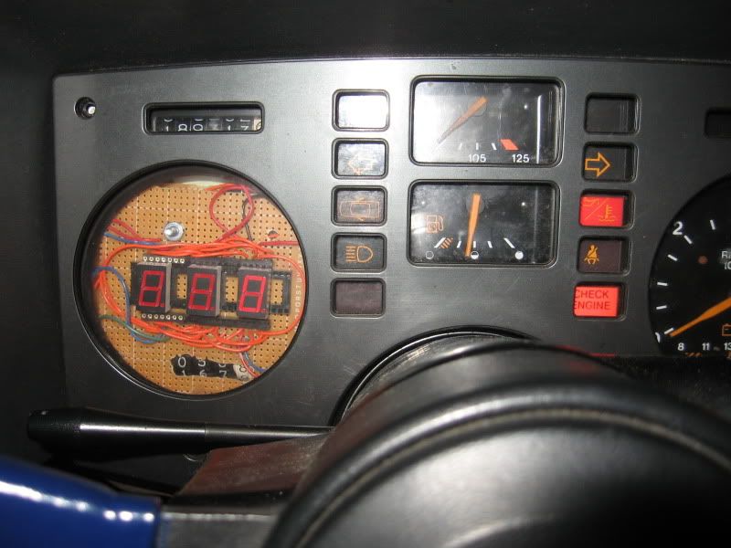
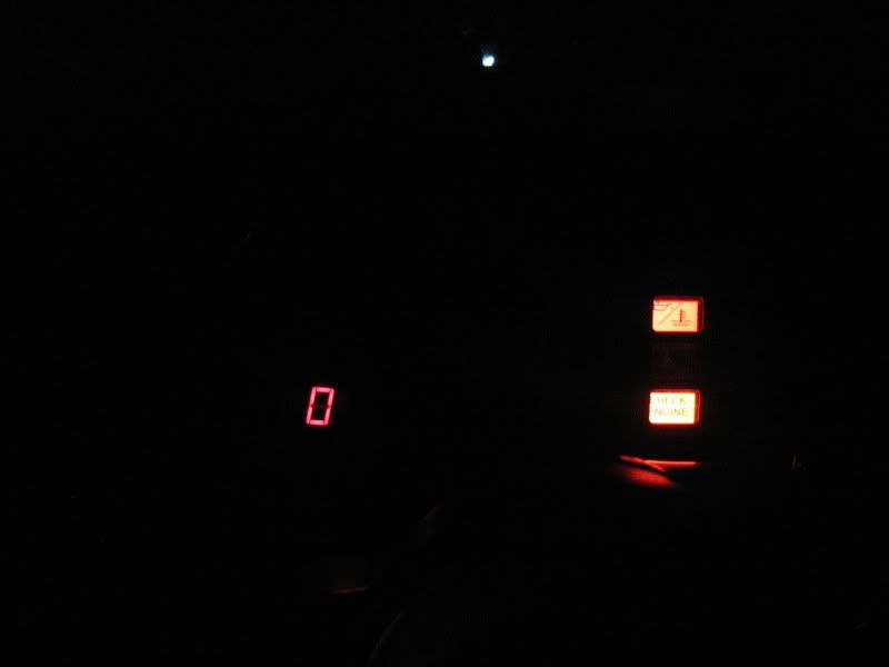
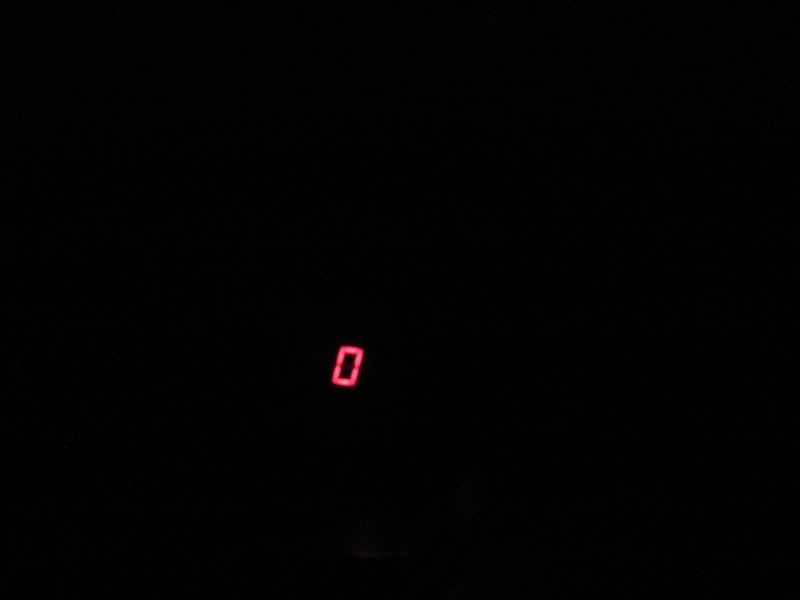
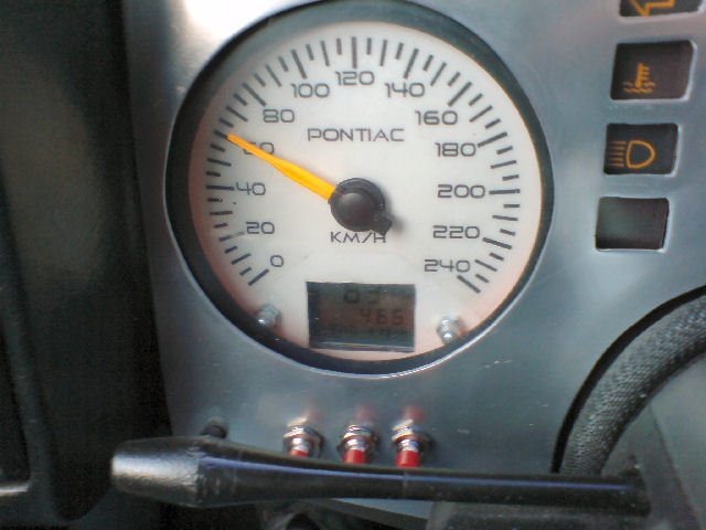
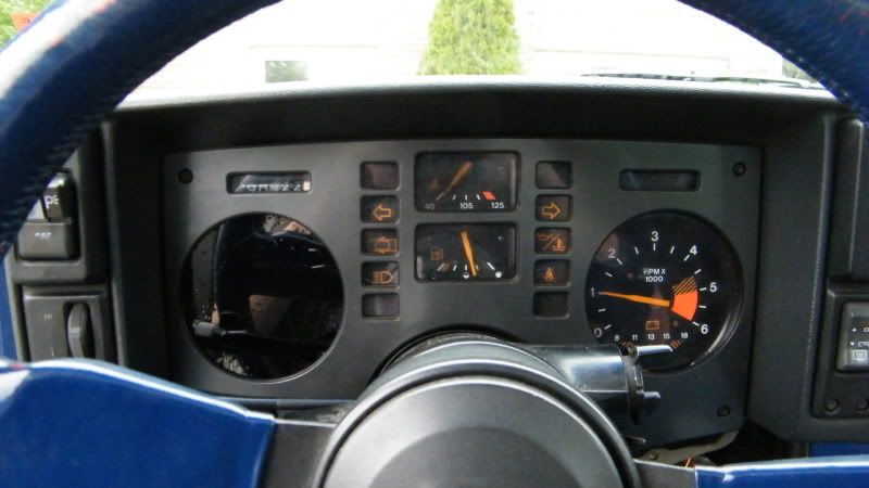
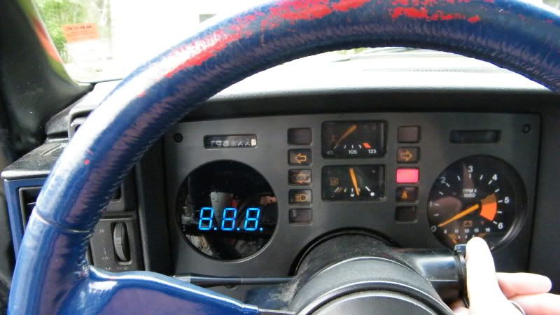
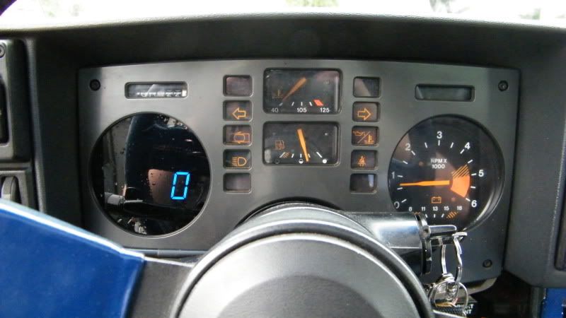
So, at the beginning of the thread, the pictures everybody sees are just of the building of the speedometer. The other day, the rest of the parts had come in, and its done. Well, maybe just a touch-up is in order. but not at this instant. So, without further delay:
The result is great. With the tint there, you see nothing at all (not any of that mess that was present in the first few pics.), and accuracy is unbelievable. It is right on par with a GPS system.
Future plans is to make my own RPM gauge, with smaller 7-segments though. Maybe a gauge that tells the driver how much fuel is remaining in the tank. A bar-graph for temperature, and battery. Note: These will not be done this summer by any means, just when I have got the time to tinker.
Hope you like, and please leave comments (good, or bad) Brian
IP: Logged
07:50 AM
ltlfrari Member
Posts: 5356 From: Wake Forest,NC,USA Registered: Jan 2002
The tinted cover is actually the plastic piece under the bezel, with tint.
The circuit was not created by myself, and is released under the GPL. You can find this at www.randomwisdom.com The creator's name is Jeff Hiner, all credit should be given to him for the work. The circuit uses a PIC16F648A, (code available there as well). Mutliplexing the 7-segment displays. Read comments, discussions resolve issues I had come across.
Note: I am not trying to cut anyones throat who is selling speedometers, I was asked about the circuit, and don't find it incorrect to release details as it is easily found doing a google search.
Brian
IP: Logged
12:22 PM
ltlfrari Member
Posts: 5356 From: Wake Forest,NC,USA Registered: Jan 2002
I appreciate the link. How are you obtaining the trigger signal to the microprocessor. From the circuit and comments it looks like it uses a reed switch and magnet on the axle. I was hoping for something a little more sophisticated. I was trying to use the VSS signal and an op amp or two to 'square' it up but was having a lot of trouble with false triggers due to noise in the vss signal itself. The rest looks to be pretty standard. In fact my design used latch/drivers to hold the current 7 seg output so that the PIC did not have to spend it's life refreshing the 7 seg displays, just set and forget.
You can see what I did on my web site.
Edit. I read your comments on his web site. It looks like you are a tapping into the output from the on board chip in the original speedo (the one that goes to the ECM). Is that correct? I was trying to avoid that.
Nice effort though (plus you're ahead of me!). + to you.
Yes, the signal that i am tapping into is the output to the ECM, using a filter capacitor to block out the noise going to the PIC. I will def. check out your site! Any questions on this build, I'll be glad to help with.
Using the PIC allows for less components, and makes it easy to build a housing unit to put in place of the analog gauge.
Brian
IP: Logged
03:46 PM
ltlfrari Member
Posts: 5356 From: Wake Forest,NC,USA Registered: Jan 2002
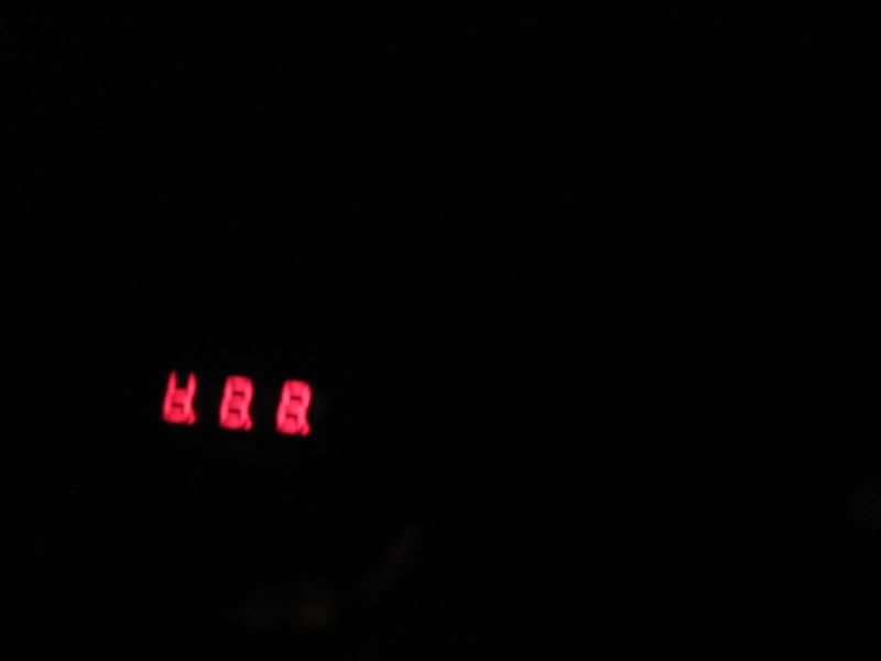
Hey, its true that you can't see the tripometer, but that is something i am going to fix up after. Will probably do this by placing white or blue leds facing them to turn on when the speedometer turns on.
As for producing and selling, it was thought about. I wouldn't mind doing it if it were my own work, but where I had got the code and stuff from someone else, I find it unethical to do such. So as of right now, the only thing I am willing to do, is offer advice if anyone decides he/she wants to build their own speedometer using Jeff Hiner's design.
Thanks for the comments, and will post pictures again when I get the trip showing again. Also, I am soon going to begin working on a digital RPM gauge, this will take more time, but will hopefully be all my own work so re-sale would be possible.