| | | quote | Originally posted by CC Rider:
Spent all day yesterday with the drawings you provided above.
Went thru each page line by line. This was a big help for a beginner like me and much appreciated. Below are the issues I have up to this point. Any help you can give me would be great.
This is a 94 motor that I�m wiring as a 92 manual to go into my 88.
This is what I have not connected or have questions about.
From the RS center:
�Brown wire labeled Ignition Fuse
�Red wire labeled Fuel ECM Fuse � this red wire has a big circular ring connector that has a grey wire spliced to the end marked as a fusible link. This red wire was loomed with another red wire that has a grey plastic connecter at the end that is connected to the fuel pump relay.
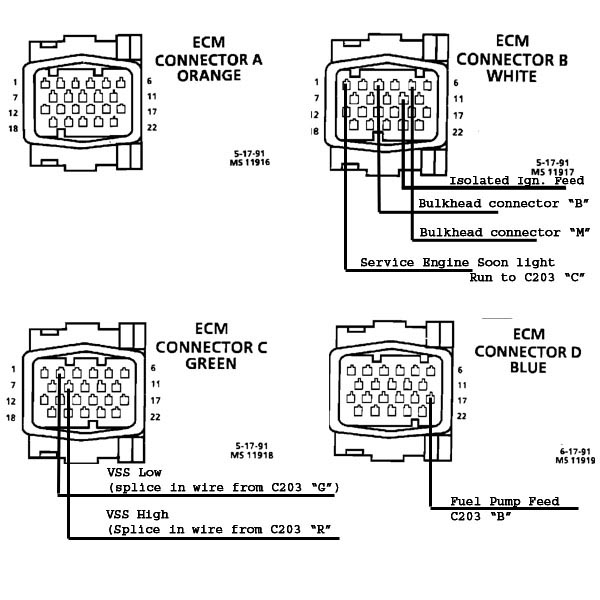
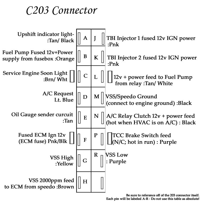
C203 wires not connected:
�Brown (H) ECM � when a magnetic VSS is connected to Speedo
�Purple (P) TCC Brake Switch
�Pink (J) TBI Injector 1 ( I would like a clear pointer on #2 as well)
�Blk/Wht (N) AC Power
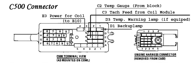
C500 wires not connected:
�Yellow (E2) Starter Solenoid ( mine is yellow because the C500 came off an auto fiero harness but I think it should be purple � I moved it to E2)
�Drk Blue(C1) Backup Lamp
�Drk Green (D3) Hot Temp warning indicator lamp feed
�Lt Green (E1) Backup Lamp feed from tranny
DIS Question:
�C1 connection � I see no connector in the harness to connect to this?
Other items to deal with:
�On the motor below the harmonic balancer is a 3 wire connector hanging lose.
�I need to wire up the Air pump system ( to include the relay to drive it)
|
|
This is what I have not connected or have questions about.
From the RS center:
�Brown wire labeled Ignition Fuse
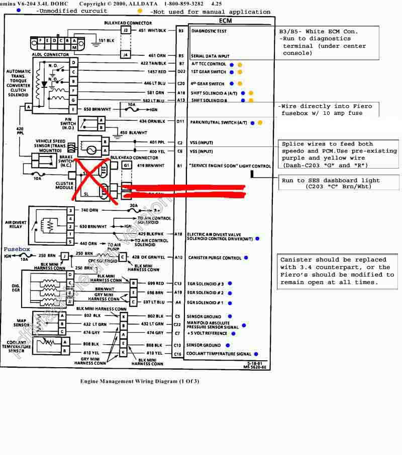
Goes to E3 ignition switched pink wire on C500. Runs EGR, alternator exciter wire ( F pin) and cansiter purge solenoid.You can also run your airpump relay from that circuit.Change Fiero IGN fuse from 20 to a 25 amp to run this circuit
�Red wire labeled Fuel ECM Fuse � this red wire has a big circular ring connector that has a grey wire spliced to the end marked as a fusible link. This red wire was loomed with another red wire that has a grey plastic connecter at the end that is connected to the fuel pump relay.
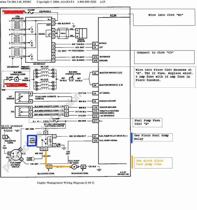
The fuel/ecm fuse will run to the B pin on the C203. Change the Fiero F Pump fuse from a 10 amp to a 20 amp
C203 wires not connected:
�Brown (H) ECM � when a magnetic VSS is connected to Speedo
not used
�Purple (P) TCC Brake Switch
not used
�Pink (J) TBI Injector 1 ( I would like a clear pointer on #2 as well)
Run that to your DIS pink/black wire but be sure to change the fuse to a 10amp in the Fiero fuse box.TBI 2 is pin K on the C203. Run your injector hotwire ( pink/black) to that and change to 10 amp as well
�Blk/Wht (N) AC Power.
.
not used for the DOHC but you could use it for an amp or other accesory
C500 wires not connected:
�Yellow (E2) Starter Solenoid ( mine is yellow because the C500 came off an auto fiero harness but I think it should be purple � I moved it to E2)
That is correct ..even though its yellow it will go to starter solenoid from the E2 pin
�Drk Blue(C1) Backup Lamp
Hot feed used for back up switch on Getrag and isuzu trans ..if using a muncie 4 speed it will be used on the shifter mounted switch
�Drk Green (D3) Hot Temp warning indicator lamp feed
not used
�Lt Green (E1) Backup Lamp feed from tranny
used for back up switch on Getrag and isuzu trans ..if using a muncie 4 speed it will be used on the shifter mounted switch
DIS Question:
�C1 connection � I see no connector in the harness to connect to this?
Can you be more specific? C1 ????
Other items to deal with:
�On the motor below the harmonic balancer is a 3 wire connector hanging lose.
second crank sensor used on the 94- 97 DOHC.If using 91 -93 9396 ECM, it is not used
�I need to wire up the Air pump system ( to include the relay to drive it)
I will get back to you when I get a chance to write up a diagram of the circuit
[This message has been edited by Erik (edited 07-13-2007).]


 So hang tight and I will have many more educated answers shortly.