I realize this may need to be in tech, but I think more people will benefit having it in here. This took about 5 hours to put together, so if there are some mistakes (grammical, or punctual) forgive me, I'll go back and edit later.
On one recent trip I took I didn't realize that my cruise was engaged, I had stepped on the brake, but apparently it wasn't hard enough and I nearly rear ended some one. I remembered one project that I was recently working on had that had a "cruise engaged" light that came on when the cruise control speed was set. I checked out the wiring between the two cars and came to the conclusion that both cruise modules were the identical and both had the same inputs and outputs, and that the Fiero module didn't use that particular output. After some careful experimentation I found that the cruise module would output a ground when the speed was set. I then set out to install this into my car while attempting to make it look as factory stock as possible. I have a number of other things that I have done to my fiero, that to the un-initiated would look completly stock from the factory. I think that this mod is one of them and I hope you'll agree. I found this to be a fairly simple mod, that someone with moderate electical knowledge and skills, should be able to accomplish in an afternoon.
This mod was done on an 86 SE with a standard trans, it is also is equipped with an aux cluster. Which makes the wiring differ from other models. You should be able to do this on any model, you just need to switch the location of the bulb in the cluster. I will show you the two different locations that you can use.
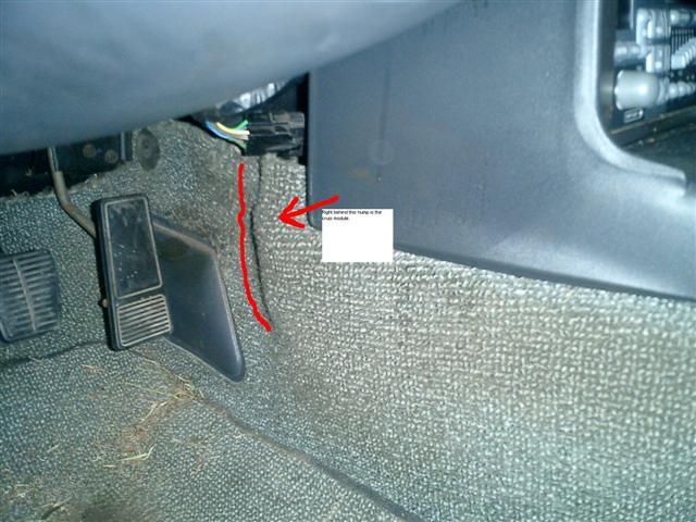
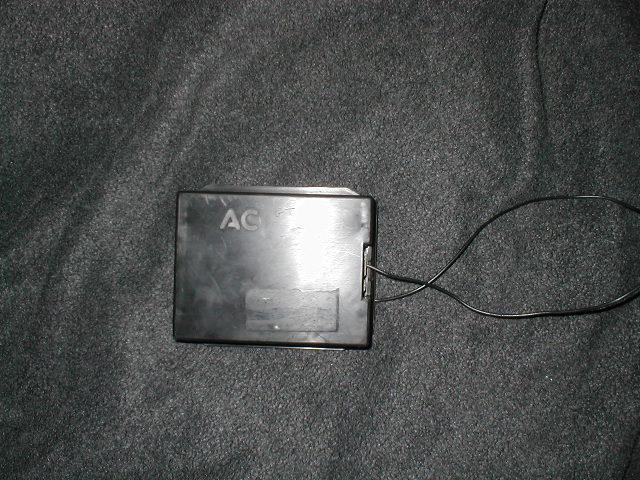
Lets start...... First remove your cluster from the car including removing it from the binnacle (surround). Now remove your cruise module, for those that may not know your cruise module is, it is located by your right foot on the drivers side.... See that hump?....Right under there is your cruise module you just need pull back the carpet, and carefully remove it. (ok I just noticed that you cant read whats in the box...thats gonna suck)
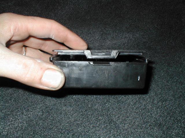
You have to remove the cruise circuit board from the case. To do this you need to depress the latch on the end and it should open right up.
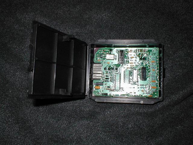
You should have what looks like this.... Remove the board from the case and set them both aside temporarily we'll get back to them in a minute. (NOTE:Yours may look different, don't worry about it, this one is a demo model that i had lying around I left the Fiero specific one at work)
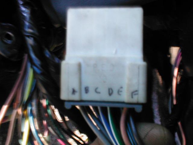
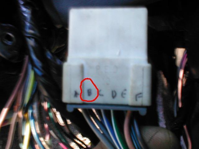
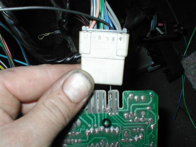
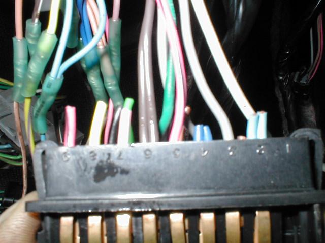
Take a look at the cruise connector that you disconnected from the module in step one.... See those letters on the end? Those letters correspond with the tabs on the circuit board that you just removed. (I labled mine for easire identification)
Now, take a second look at the connector, look for the letter "B". This is the terminal that we are going to work with.
Continued........I ran out of space for pics.
Why does it say maximum of 8 images and you can only post 6! ARRGH!! nevermind, I just found out thanks jake_dragon
------------------ A coward dies a thousand deaths..................A soldier dies but once. Red 86 SE Yellow 87 GT Gold 86 SE (wrecked) Red 84 2.5 Coupe
[This message has been edited by Fierofreak00 (edited 10-16-2005).]
IP: Logged
12:47 PM
PFF
System Bot
Fierofreak00 Member
Posts: 4221 From: Martville, NY USA Registered: Jun 2001
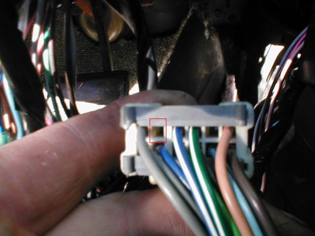
If you turn the connector on end you'll noitice that "B" is an empty cavity..... This is where we are going to install the control wire for the dash light.
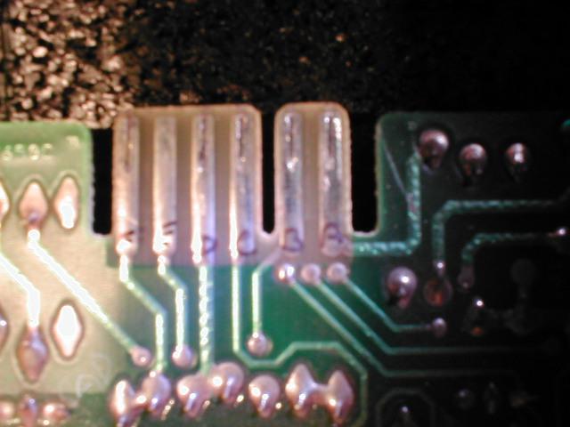
The next thing you are going to need is a piece fo 22 gauge wire about 2 ft long or longer as you can always trim it. 22 gauge is very inportant here, as it will have to fit thru the connector in the next steps. This is going to be your control wire. (NOTE: For those that know how, you can actually remove a terminal from a spare connector and install in the empty terminal of your cruise connector. That is the way I did it, but removing the connector was a real pain and I've been working on cars for quite a while now. I came up with this alternate way so that the novice electrician can accomplish the same thing only easier.) Take the 22 gauge wiring and solder it to the terminal marked "B" like so (you remembered to label it didn't you!)
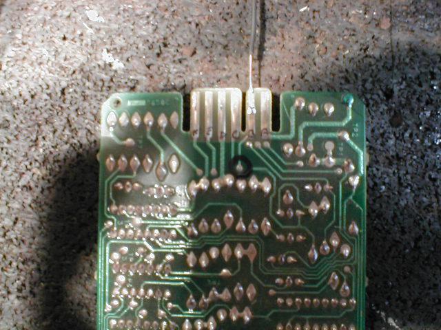
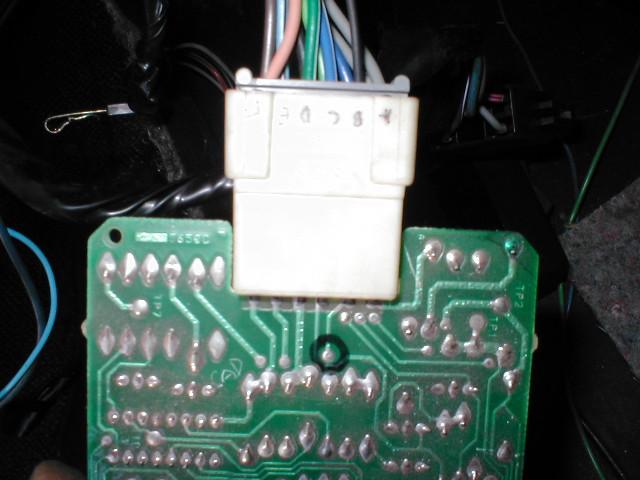
Now reinstall the circuit board into the case, being careful to fish the wire back out the front. You should now have something like this:
Take the wire and push the wire thru the empty cavity in the cruise connector (remember when I said you needed to use 22 gauge!) Don't worry, it will fit with some coaxing. You should now have this:
Once you have the wire thru, seat the connector like so ( I have my case was removed for clarity, imagine that it is there, and this is what yours looks like)
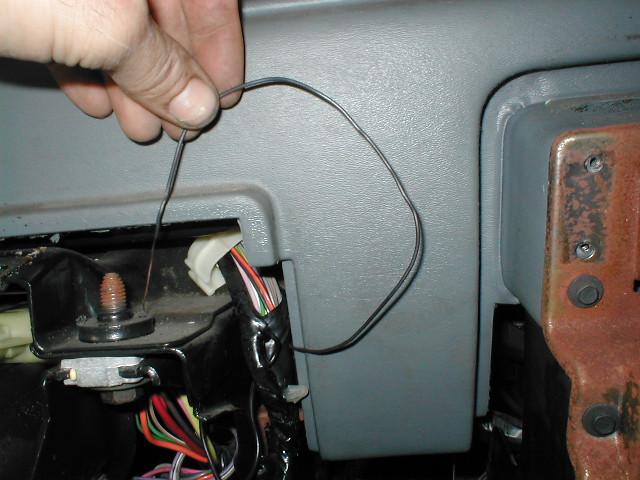
Reinstall your cruise module and snake the wire up behind the instrument cluster so that you have a pigtail like this.
Cont......
[This message has been edited by Fierofreak00 (edited 10-16-2005).]
IP: Logged
01:03 PM
HI-TECH Member
Posts: 1697 From: manteca, california Registered: Jul 2005
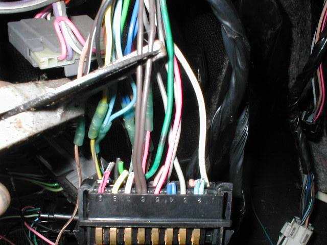
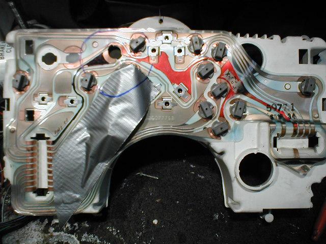
Next locate connector C-1, It's that big 18 pin on right side of cluster, and find pins 5 (pink/black) and 6 (brown). Pin 5 is a switched ignition feed for the charge light on vehicles without aux gauges. On vehicles with aux, it does absolutely nothing. Pin 6 is the control side of the circuit, as well as the splice point for the feed to the aux gauge charge light. Remember aux gauges can be installed on cars not originally equipped so all cars are actually set up this way.
I am going to continue with the mod using my car, which has the aux gauges. I will also show you an alternate way if you car has a charge light.
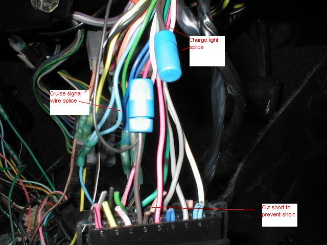
See those brown wires on pin 6? You need to cut those off while leaving yourself about an inch of pigtail at the connector like so..
The two wires you cut off need to be spliced together to retain the operation of your aux gauge idiot light (if so equipped).. You then need to trim one of the two connector wires short, to prevent shorts (no pun) and then splice the control wire (from the cruise module) to the other brown wire. You should use some type of connector here (IE spade, bullet) to ease removal of the cruise module if needed in the future. I used posi locks here ( I like them alot and they are reuseable).
Although the next pictures are redundant, I feel it is important to post them (and I took alot of time to prepare them).
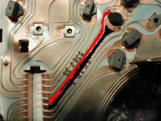
Trace the back of your cluster to find the unused socket for the charge light. This socket is blank on cars with the aux set up. I tried to make it easier to identify by coloring the lands on the circuit board. I also used red and black to signify + and -.
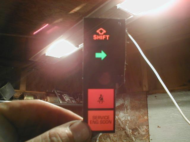
The next image is for cars without aux gauges, it utiliizes the shift light socket. People with autos will be able to use this with no problem as the autos dont use it anyway. People with standards now have to make a decision to disable the shift light or keep it (most people I talked to don't use it anyway). The shift light wire on connector C-1 pin 1 (large 18 pin) needs to be cut and spliced just like the charge light except, you don't have any extra wires to splice together.
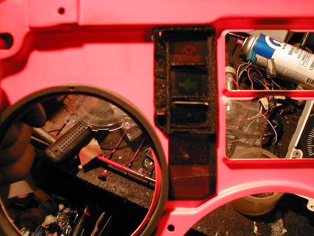
Now it's time to modify the light faces (lense?). Disassemble the cluster to remove the right turn signal lense, notice that the third one down is blank (again aux gauge equipped) This is where we are going to modify to accept the cruise filter (or the shift indicater if you are putting it here).
Cont........
[This message has been edited by Fierofreak00 (edited 10-18-2005).]
IP: Logged
01:51 PM
Fierofreak00 Member
Posts: 4221 From: Martville, NY USA Registered: Jun 2001
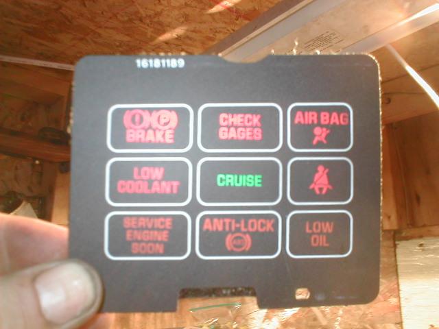
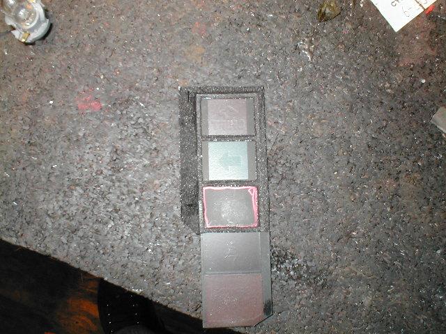
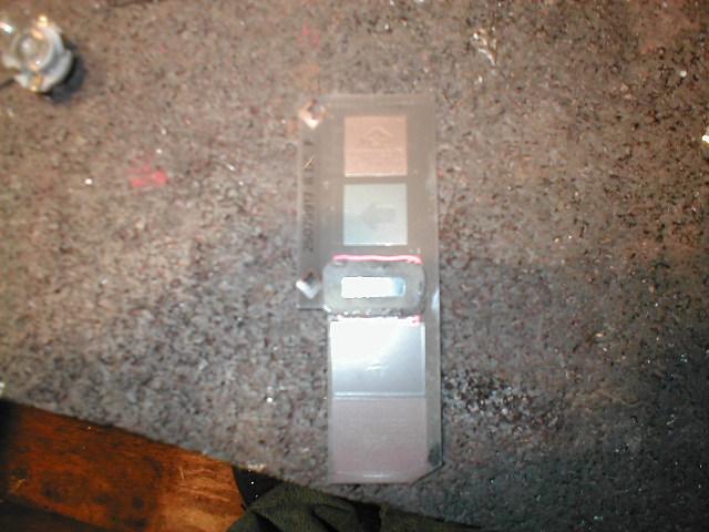
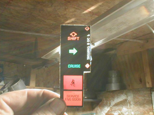
Now take the previously aquired light filter (lense) that you got from the junkyard, it may look like this one (I hope you got it before you took everything apart!) Oh and be sure it has the "cruise" filter on it.
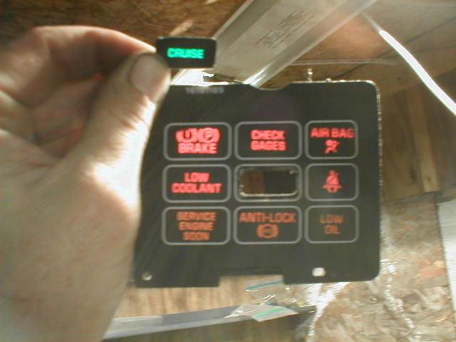
You are going to cut the portion out that says (obviously) "cruise" like this. Be careful not to cut or scrape the letters (It WILL show).
Retrieve the right signal lens you just removed, and out line the box on the back side using the foam as a template.
This allows you to get an idea of where to cut after the foam is removed.
Place the "cruise" cut out on top of your outline to get an idea of where you are going to cut the slit for light to pass thru. (Note: do not center the lettering in the box, you need to bias it towards the top just slightly. This is because when you are sitting in the car and viewing it, you actually look down at it. And if it was exactly centered, it would appear too low in the box) Measure, Measure, Measure you only get to cut once! You should have a slit similar to this if you did it right. (pay no attention to the tape I forgot a pic!)
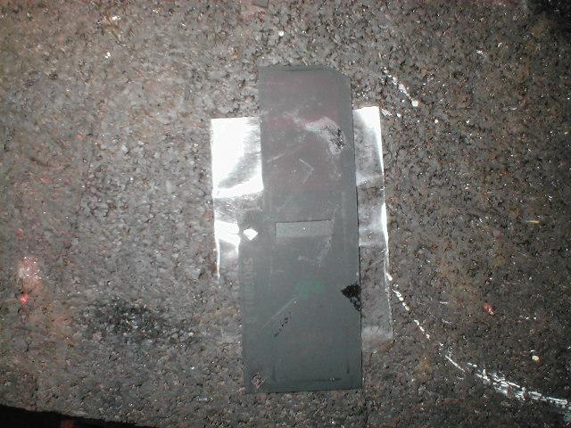
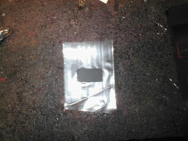
Take your cut out and place it on top of a Scotch type tape (I use packing tape) face up, Like so.
Continued.......
[This message has been edited by Fierofreak00 (edited 10-16-2005).]
IP: Logged
02:12 PM
Fierofreak00 Member
Posts: 4221 From: Martville, NY USA Registered: Jun 2001
Install and center in the slit you just made, shine some light thru the filter and if you did it right it should come out like this, (looks factory, doesn't it!) Try to get it taped the first or second time, the tape might not stick as well if you get your ginger prints all over it. Plus, you don't want to be removing the cluster again, just to reinstall the cutout if it falls off.
Reinstall the lense back into the metal cut out like this
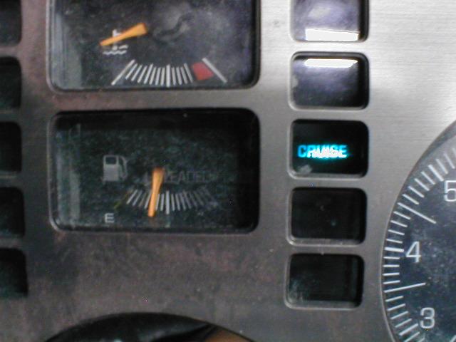
Reassemble your cluster, put the cluster face back on and shine a flashlight thru it. If it looks like this.... You're done! If not you have to re align it again. Now reinstall your cluster and all componets you removed. Go enjoy a test drive, and verify the operation of your new cruise light. The light will only come on when the cruise is engaged (speed set) and not when the switch is in the on position.
I tried to be as clear and as precise as I possibly could, I also attempted to provide as many pics as I could. BUT there are many variables to YOUR install, and if you decide to undertake this mod, YOU are responsible if something is messed up. I can not account for every little nuance of each car this is only intended as a guide line to help you in you mod. If you have any problems with your install drop me a line and I'll help you he very best I can. Good luck! -Jason
FINISHED!! Now I can eat lunch!!
[This message has been edited by Fierofreak00 (edited 10-16-2005).]
IP: Logged
02:24 PM
Sparkjl Member
Posts: 182 From: Indy,Indiana USA Registered: Jul 2002
When are you going to come out with the Mod Kit? Thanks for showing us that in such detail, I'll be putting that on my list of things to do. The more lights and gizmos the better for me!
IP: Logged
05:04 PM
buddycraigg Member
Posts: 13620 From: kansas city, mo Registered: Jul 2002
Originally posted by Fierofreak00: The next image is for cars without aux gauges, it utiliizes the shift light socket. People with autos will be able to use this with no problem as the autos dont use it anyway. People with standards now have to make a decision to disable the shift light or keep it (most people I talked to don't use it anyway). The shift light wire on connector C-2 pin 1 (small 12 pin) needs to be cut and spliced just like the charge light except, you don't have any extra wires to splice together.
Ok, I�m confused. It looks like the ground for the shift light is on pin 1 of C-1 (big 18 pin)
thumbs up on the cool trick.
IP: Logged
05:19 PM
PFF
System Bot
CoolBlue87GT Member
Posts: 8481 From: Punta Gorda, Florida, USA Registered: Apr 2001
Excellent post as I was just thinking of doing this & wonder what I was going to get into.. I bow down to you for this thread. Thanks a million. Rick B
Cool idea, even though my cruise doesn't work . I'll have to keep this in mind if I ever get around to fixing the cruise control. "+" for taking the time to post your write-up.
[This message has been edited by GT86 (edited 10-16-2005).]
IP: Logged
06:31 PM
Deabionni Member
Posts: 4088 From: Kalkaska, MI Registered: Mar 2004
Ok, I�m confused. It looks like the ground for the shift light is on pin 1 of C-1 (big 18 pin)
thumbs up on the cool trick.
It is, remember that the cruise module uses a ground to turn on the light. I only highlighted the circuits to illustrate where they come from and where you need to add the control circuit. Pin 9 is the switched power feed just like pin 6 using the charge light socket. -Jason
IP: Logged
06:46 PM
Fierofreak00 Member
Posts: 4221 From: Martville, NY USA Registered: Jun 2001
Do all manual trans. cars have shift lights factory?
Buddycraigg is right, I didn't know that mine had one, until I took the cluster out to replace a blown bulb. I simply inserted a new bulb and viola the light worked.-Jason
IP: Logged
06:49 PM
Fierofreak00 Member
Posts: 4221 From: Martville, NY USA Registered: Jun 2001
When are you going to come out with the Mod Kit? Thanks for showing us that in such detail, I'll be putting that on my list of things to do. The more lights and gizmos the better for me!
I just believe in making mods look factory, plus I really wanted to share with others. I consider myself a pretty mechanically inclined person ( I work at a Dodge dealership) but I have seen some writeups that make me scratch my head trying to figure out how to make something work. So I labor over getting things just right before I post...just so you will understand without a doubt.
If you like this one wait until you see my next one........stay tuned.
IP: Logged
07:11 PM
PFF
System Bot
Gordo Member
Posts: 2981 From: East Guilford, NY, USA Registered: Mar 2002
I went to give you a "+" but I already had. Figuring out what the module set when cruise was on was on my list of things to do...you saved me the effort. I will probably incorporate this into my firebird dash, although they don't have cuise lights stock either.
IP: Logged
08:34 PM
buddycraigg Member
Posts: 13620 From: kansas city, mo Registered: Jul 2002
It is, remember that the cruise module uses a ground to turn on the light. I only highlighted the circuits to illustrate where they come from and where you need to add the control circuit. Pin 9 is the switched power feed just like pin 6 using the charge light socket. -Jason
ok. for us SHIFT LIGHT people is it C-2 pin1 or C-1 pin1?
cause you've said both
Crap sorry, I now know what you meant! C-1 (18 pin), pin 1 which is the black trace in the second picture that is the one you want to splice to the control wire from the cuise module. I also edited the original post to reflect that. Again Buddycraigg, I'm sorry that I misread your original question. I hope this clears it up for you. -Jason
I know the connectors are actually called differently by GM in the manual but in the interest of keeping it simple I just used the term c-1, c-2.
IP: Logged
10:14 PM
PFF
System Bot
Mister Member
Posts: 1975 From: Calgary, Alberta, Canada Registered: Aug 2004
Originally posted by Fierofreak00: Crap sorry, I now know what you meant! C-1 (18 pin), pin 1 which is the black trace in the second picture that is the one you want to splice to the control wire from the cuise module. I also edited the original post to reflect that. Again Buddycraigg, I'm sorry that I misread your original question. I hope this clears it up for you. -Jason
thanks i wanted to be sure i didn't fry something or create a subspace tear
IP: Logged
12:55 PM
Fierofreak00 Member
Posts: 4221 From: Martville, NY USA Registered: Jun 2001


 Thanks for showing us that in such detail, I'll be putting that on my list of things to do. The more lights and gizmos the better for me!


 . I'll have to keep this in mind if I ever get around to fixing the cruise control.