i replaced all my front end components ie. ball joints, Tie rods, bushings. i used rodney's 1" lowering lower ball joints and the adjustable upper ball joints. now the problem - i have posotive camber and i pushed the upper as far in as i could but still have posotive camber. i dont have room to make the holes in the controle arm bigger to make more adjustments. i will take pictures of the car and post them soon so you can see what i mean. im not sure what to do now or how to fix it. any help would be greatly appriceated.
i did not do any other lowering components and this is in regards to the front only. everything else is stock except for the poly bushings.
Thank you, Steven
------------------
4 cyl, 2.5 L Manual 4-spd 4.10 Regular Gasoline EPA Fuel Economy Miles per Gallon Regular Gasoline 24 Combined 21 City 29 Highway
IP: Logged
01:46 PM
PFF
System Bot
TONY_C Member
Posts: 2747 From: North Bellmore, NY 11710 Registered: May 2001
I just did the same to my 84, new components all around and 1" lowering ball joints too. I had the same issue with chamber. I had to push the upper ball joints all the way inboard and even then it' in spec but on the end of the tolerance. Are the two mounting holes in your ball joints slotted? I think on some ball joints they have to be rotated 180* to get the movement you need, not 100% sure about that though. Did the front end get lowered with the new lower ball joints? mine really didn't move that much and it's been two weeks now so I assume it has settled already. I knew I should have cut half a coil too.
IP: Logged
01:56 PM
My84 Member
Posts: 221 From: Billings, Mt Registered: May 2008
I just did the same to my 84, new components all around and 1" lowering ball joints too. I had the same issue with chamber. I had to push the upper ball joints all the way inboard and even then it' in spec but on the end of the tolerance.
1- Are the two mounting holes in your ball joints slotted?
2- I think on some ball joints they have to be rotated 180* to get the movement you need, not 100% sure about that though.
3- Did the front end get lowered with the new lower ball joints? mine really didn't move that much and it's been two weeks now so I assume it has settled already. I knew I should have cut half a coil too.
1- yes the upper balljoint is slotted. 2-the oem ball joints you can rotate them 180* . But with Rodneys slotted upper ball joints Rodney believes they are semectrical ( dosent matter what way they are installed) 3- i did notice a little bit but it is only a 1" drop. With Rodneys 1" drop lowering lower ball joints.
[This message has been edited by My84 (edited 09-07-2012).]
IP: Logged
04:01 PM
My84 Member
Posts: 221 From: Billings, Mt Registered: May 2008
What is the camber reading on the alignment rack? And as for lowering, I was expecting to see the nose drop one inch. not sure why it didn't get that low.
IP: Logged
04:27 PM
My84 Member
Posts: 221 From: Billings, Mt Registered: May 2008
What is the camber reading on the alignment rack? And as for lowering, I was expecting to see the nose drop one inch. not sure why it didn't get that low.
i didnt take it to a shop yet so i dont know how far out it is but i can see that it is posotive camber. but i want it to be more negative b4 i take it to a shop for a proper alignment. ( no use paying if it cant get alligned in the first place )
as for if it looks lower yes it dose to me. i can tell the differance int he wheel well. i can also tell from the drivers seat. i can see more of the road.
IP: Logged
08:43 PM
My84 Member
Posts: 221 From: Billings, Mt Registered: May 2008
Bump for ideas to try tomorrow on how to fix this problem. i will be taking the pictures tomorrow as well as turning the upper ball joint 180* to see if there is a differance.
IP: Logged
08:44 PM
Sep 8th, 2012
My84 Member
Posts: 221 From: Billings, Mt Registered: May 2008
i measured the ride hight from the ground to the fender then jacked up the car removed the tire placed a jack under the lower control arm and removed the first jack. i then sat on my car to get the suspension to squat and lowered the car so the fender was at the same hight as befor i jacked up the car and then lossend the upper ball joint
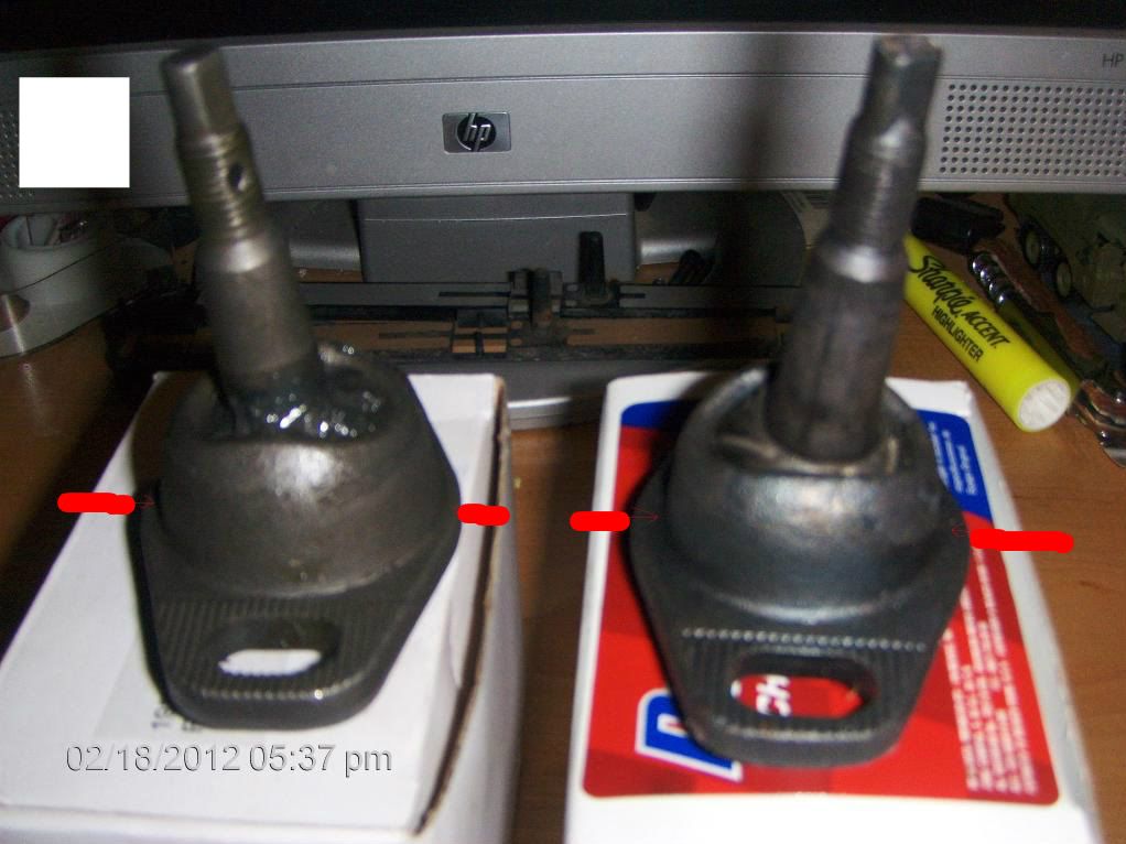
This picture is with the ball joint pulled out to make the most positive camber that i can.
This picture is with the ball joint pushed in to make the most negative camber that i can ( still posotive )
this picture is of the ball joint in the upper control arm and pushed in as far as it will go ( trying to see what i have to work with to make negative camber )
now it looks like the only thing i can do is to make the holes bigger for the ball joint and remove the yellow sections. ( i dont have tools to do that, all i have are a limited amount of hand tools )
[This message has been edited by My84 (edited 09-08-2012).]
I had the same problem with the adjustable upper ball joints. It seems to me that the base of the ball joint, (where it actually passes through the control arm) doesn't have any room to adjust. That portion of the adjustable ball joint hits the edge of the hole in the control arm and wont adjust in anymore.
About 3/4 way down on the first page you will see a pic I edited to show the differences in upper ball joints. The base is too wide and fills the upper control arm hole before most adjustment can be made. I was considering cutting some of the hole larger with my dremel. That sounds like a bad can of worms though. https://www.fiero.nl/forum/Forum2/HTML/121154.html
I'm very interested to see how this pans out. I still need a proffesional alignment and would like to fix this before I take it in.
Heres a pic where you can see the difference in ball socket bases.
IP: Logged
12:12 PM
My84 Member
Posts: 221 From: Billings, Mt Registered: May 2008
I had the same problem with the adjustable upper ball joints. It seems to me that the base of the ball joint, (where it actually passes through the control arm) doesn't have any room to adjust. That portion of the adjustable ball joint hits the edge of the hole in the control arm and wont adjust in anymore.
About 3/4 way down on the first page you will see a pic I edited to show the differences in upper ball joints. The base is too wide and fills the upper control arm hole before most adjustment can be made. I was considering cutting some of the hole larger with my dremel. That sounds like a bad can of worms though. https://www.fiero.nl/forum/Forum2/HTML/121154.html
I'm very interested to see how this pans out. I still need a proffesional alignment and would like to fix this before I take it in.
( eddited to add the correct picture )
i hope you dont mind i used your picture and added my ideas.
i to dont feel comftorable cutting/grinding the UCA either. so now my idea is - the thickness on rodneys upper ball joint appears much thicker ( meaning the thickness from where the ball is to th out side of the case - in green / and where it looks like more metal is added around the base from welding or strengthining? in white ) than that the oe from a parts store so what if we then grind down one side of the ball joints that we got from rodney hlighted in yellow in the pocture above.
i would like to get a thickness gauge and open up both ball joints and pull out the ball/stud to see how much thicker rodneys ball joints are and if there is room to grind down without compromising the integrity of the upper ball joints.
Has anyone wtih an 84-87 installed the 1" lowering ball joint and adjustable upper ball joint from rodney and did not have any problems with getting your car alligned please post pictures of your upper controle arm mainly the underside of the mounting hole for the upper ball joint. this will be extreamly helpfull.
Thank You Steven
[This message has been edited by My84 (edited 09-09-2012).]
well i took it to the alignment shop and my camber i was + 0.7 on drivers side and +1.3 on passenger with no room for getting a negative reading.. i ended up grinding the control arm hole for the upper balljoint. when i started the diamiter was aproxamently 45-47mm. i ground the openings to 50mm. my second allignment check after grinding was 0.0 on drivers side and + 0.7 on passenger. i didnt feel comftorable grinding out any more so i had them get as close to 0 as they could and make them match. ended up with a +0.3 on both front after alignment. im not sure what to do now apart from 1 - making or having someone make custom control arms with room for more adjustments. 2 - get different upper balljoints from autopart store that will have a little more room for adjusting ( not much ) 3 - drill out control arm mounting bolt holes in frame and make them adjustable ( make them elongated ) or 4 - go back to factory lower ball joints instead of 1" lowering.
thats what i was able to come up with. i hope someone has some more ideas.
Thanks
IP: Logged
09:36 PM
Sep 22nd, 2012
Boostdreamer Member
Posts: 7175 From: Kingsport, Tennessee USA Registered: Jun 2007
Has anyone talked to Rodney about this? I've got his adjustable upper balljoints as well as his one inch drop lowers waiting to go on my car. I don't want to start this job unless I know it will all go together correctly.
I've read that trying to rotate the RD upper 180 degrees might be a solution. I tried it, twice. The first time it put my RF tire WAY out on the top edge, way out!. So I turned it back 180 degrees to the way I had it at first. That made it much better but It is still out on top. Cooked a tire...
Honestly, as soon as I can I'm gonna pull the RD adjustable uppers and toss some parts strore adjustables in and see how they fit.
IP: Logged
11:49 PM
Sep 23rd, 2012
Boostdreamer Member
Posts: 7175 From: Kingsport, Tennessee USA Registered: Jun 2007
I looked at some old emails but it seems I did not save many. I originally had a few prototypes made and I sent a set to an engineer who also raced a 84-87 Fiero. I'm not sure what he did. I'm guessing he slotted all the holes inward and ground some on the outer ring to make them align well. I can say I've sold more than a few hundred sets now. Most seem to get them to fit with some modifications to the arm and ball joint. No one has told me they can net get them to fit recently. I have an arm and ball joint on my work bench. Someday soon I'll work on it and see how much I can easily get. I'll take some pictures. On my 88 Mera I installed the Held drop spindles and the Link power steering. I had to do a lot of changes etc to make it all fit. But in time I did get it all to fit.
------------------ Rodney Dickman
Fiero Parts And Acc's Web Page: All new web page!:www.rodneydickman.com Rodney Dickman's Fiero accessories 7604 Treeview Drive Caledonia, WI 53108 Phone/Fax (262) 835-9575
Grinding BJ body is a bad idea. Grinding etc may cause stress risers to start.
Grinding CA big hole above is ok but Don't slot bolt holes.
------------------ Dr. Ian Malcolm: Yeah, but your scientists were so preoccupied with whether or not they could, they didn't stop to think if they should. (Jurassic Park)
I just looked at this. Easy as pie. Grind the large hole inward some. I also had to make it slightly wider as the ball joint would not go in and lay flat. I'm not sure how much I went inward. Maybe 6-7 mm or so. I slotted the small holes on the control arm inward 3 mm or so. I also had to grind some on the outer flange (just on the corners) where the bolts go as the steel on the arm arm starts to ramp up. I'll take some pictures soon and post them on my web page.
------------------ Rodney Dickman
Fiero Parts And Acc's Web Page: All new web page!:www.rodneydickman.com Rodney Dickman's Fiero accessories 7604 Treeview Drive Caledonia, WI 53108 Phone/Fax (262) 835-9575
I just looked at this. Easy as pie. Grind the large hole inward some. I also had to make it slightly wider as the ball joint would not go in and lay flat. I'm not sure how much I went inward. Maybe 6-7 mm or so. I slotted the small holes on the control arm inward 3 mm or so. I also had to grind some on the outer flange (just on the corners) where the bolts go as the steel on the arm arm starts to ramp up. I'll take some pictures soon and post them on my web page.
Rodney, will this make you change your next production run of adjustable ball joints? In the event of a wreck, etc, and the ball joints had to be changed again, will local store ball joints work in modified A-arms or will they have to be replaced with one with the same dimentions?
What would be the recommended grinding tool be? I have a corded dremel but thats about it. Im thinking it might take forever and a ton of discs though.
Spare front UCAs and LCAs, both sides. So just so I have this right. In order for my newly installed adjustable upper ball joints to actually be adjustable I have to cut/grind the ball joint hole larger? Couldnt a regular, store bought upper ball become adjustable after doing this same cutting/gringing? Slot the bolt holes, same effect?
Also, might it be possible to achieve enough adjustability by only slotting 1 bolt hole?
I fixed this, pretty easy. Two dremel grinding stones. One round, one cone. Safety glasses, rotory tool. Pulled it all apart except the lower ball joint. Propped a bar under the lugnuts to keep the weight off the brake hose. Pulled the upper ball. Grind, grind, test fit, grind, grind. When I originally installed the uppers balls I made a line. You can see the difference here. Between 4-5mm.
Oh and I only had to grind one of the bolt holes. Thats where the cone shape grinding bit cam in handy.
Pretty easy fix. Probably need to do the drivers side a few mm as its starting to show the same tire wear. Then new front rubber I have already mounted and balanced. Then alignment shop.
I dont wanna cook any more 215/45 zr17 then I have to. Those werent cheap!