Issue: So I want to be sure I don't do what the previous owner did... Fry all the power wires in the whole car. Thanks to this I'm left with a car with more red 10 gauge wire then autozone and no fusible links. Now..wWhat brought me to the 140amp alternator? My stock alternator was having issues and putting out various volts while driving. It dipped as low as 11 volts and spiked as high as 15-16. Last time the car was driven it smelled like electrical burning and was reading 15+volts... Now even when it was running prefect, the stock amperage alternator could not keep up with the car's current stock demands, so with this new issue, I decided why not upgrade. So i got a polished 140 amp alternator, might as well be pretty too. I also want to beef up the wires that are associated with the electrical system before the junk ones I have fry the car.
I bought the alternator and due to the economy, daily driver issues, daughter's car, and lack of help... 2 years have past since the car has been on the road. I finally got a friend to lend a hand and the time to get the alternator back in... Amazing how hard it was to get someone to slip in a bolt and hold the darn thing while I mounted the lower bracket... LOL!
What I have left to do before I fire the little fellow back up is to be sure I have the wiring beefed up enough to not fry the electrical system. What should I replace with larger gauge wire and what gauge should I use??? I also want to convert from the 84 style wiring to the newer style and install a proper distribution block for my power wires Might I also mention that the previous owner's wiring was jacked up to the point of wrapping the "extra" length around suspension and the frame. So in all honesty, I don't trust even the gauge wire he replaced the stock stuff with. I would like to go back to "like stock" guage or better. Can someone lead me in the right place to see how I should rewire. I have searched, but I guess my key terms are lacking...
I would love to finally get my baby back on the road after 2 years!
Thank you!
Edited for better readability and clarity
[This message has been edited by redraif (edited 08-15-2011).]
IP: Logged
02:48 PM
PFF
System Bot
IMSA GT Member
Posts: 10736 From: California Registered: Aug 2007
I assume you are running some sort of sound system which is why you went to a bigger alternator? There is a difference between volts and amps. If you smelled burning at 15 volts, it is because something was either not fused correctly or something was just overheating due to the overvoltage. Having an alternator that puts out high amperage will not effect wiring and normal operation. The amperage is there only when a high-draw device needs it.....not all the time. Under normal day to day driving, the alternator acts just like a stock one. You shouldn't need to beef up any wiring unless you installed some aftermarket parts like a stereo amp. Then you may look into the gauge of wiring powering the amplifier.
IP: Logged
02:57 PM
1fatcat Member
Posts: 1519 From: Zimmerman, Mn Registered: Dec 2010
If the stock wiring is in good shape, it should be adequate. A monster alternator could produce 300 amps, but the electrical system will only draw what it needs. The extra amperage is never actually produced/used unless the electrical system demands it.
I think you should inspect your wiring for corrosion, loose connections, frayed cables. It's very likely that the old alternator had a bad voltage regulator and was causing your high voltage readings. The polished ones look nice, but they function the exact same way...aside from available amp output, and even then it's a maybe.
New main power and ground cables (off the battery) would be a good thing to replace, as they can cause a lot of problems if the cables are corroded inside (where you can't see it). They are usually pretty cheap at the parts stores ($10 each).
I assume you are running some sort of sound system which is why you went to a bigger alternator? There is a difference between volts and amps. If you smelled burning at 15 volts, it is because something was either not fused correctly or something was just overheating due to the overvoltage. Having an alternator that puts out high amperage will not effect wiring and normal operation. The amperage is there only when a high-draw device needs it.....not all the time. Under normal day to day driving, the alternator acts just like a stock one. You shouldn't need to beef up any wiring unless you installed some aftermarket parts like a stereo amp. Then you may look into the gauge of wiring powering the amplifier.
Yes I will be doing a system with 12s soon. Let me say with the stock alternator amperage, I have had horrible luck with night driving with the car stock. With the lights on, radio, any air/heat the car will barely keep running. Add in a turn signal and the poor thing will try to die. I can watch the volts drop and raise with each flash of the signal light. Headlights were dimming and surging. All this with stock everything. The volts would drop below 11... then it started running at 11 volts even in the day. Then the last time I drove the volts spiked and my spouse smelled electrical fire... they were in the car behind me. The alternator smelled when we got home. Hence the replacement. I assume it had to be it with all the inconsistent voltage reading. Not to mention I can't keep a battery in the car. They always fail. I have yet to find a draw but wonder if the alternator has been over and under charging the batteries and leading to failures. So I figured why not upgrade. Obviously the stock one could not keep up anyway at night.
Edited to fix what my phone fixed incorrectly... LOL!
[This message has been edited by redraif (edited 08-15-2011).]
If the stock wiring is in good shape, it should be adequate. A monster alternator could produce 300 amps, but the electrical system will only draw what it needs. The extra amperage is never actually produced/used unless the electrical system demands it.
I think you should inspect your wiring for corrosion, loose connections, frayed cables. It's very likely that the old alternator had a bad voltage regulator and was causing your high voltage readings. The polished ones look nice, but they function the exact same way...aside from available amp output, and even then it's a maybe.
New main power and ground cables (off the battery) would be a good thing to replace, as they can cause a lot of problems if the cables are corroded inside (where you can't see it). They are usually pretty cheap at the parts stores ($10 each).
That's the plan... I still wonder if the previous owner's three rolls of red 10-12 gauge wiring in the bay is the main issue. I have tracked and fixed most of it, but the alternator wiring was the last. I wanted to replace the power wire to starter and starter to alternator. Figure it can't hurt. That and add a dist block to make it all upgraded from stock to the newer style. Maybe the dist block will help with my starting gremlin. The Indy has a power cable from the battery to the starter and then it splits and runs the lines to the accessories. I hate the small lines running by the exhaust and wanted to incorporate a dist block instead... then replace all the power lines to accessories from there. Weeding out my gremlins. I have replaced and added many new grounds. I just don't know what are the correct gauges to run since the previous owner fired everything, not to mention what size fusible links since he took them all out. Maybe he went too small. Is anything accessory wise needed larger then a 10 or 12?
[This message has been edited by redraif (edited 08-15-2011).]
IP: Logged
03:21 PM
17Car Member
Posts: 482 From: Morrisdale, PA Registered: Jun 2009
If you get the stock wiring back in good shape, it should handle it without any problem. I have a 140 alternator in the Northstar engine in my Fiero and haven't had any problems with it yet.
See my cave.... Alt sense in charge & start section
All 84 owners should modify alt wiring in the article. 84 can over charge/volt even when alt is good because of 84's wiring. Means any weak connection can lie to alt sense pin and alt will be in over volt condition. Most likely This is one of your problems. Check Fuse Links bolted to starter.
Your case... need to rewire output & sense and use a new fuse link. Stock wiring is suspect and, no dis to you, you don't have skills to check it out. Mark sure old wires can't end up being a short in future.
------------------ Dr. Ian Malcolm: Yeah, but your scientists were so preoccupied with whether or not they could, they didn't stop to think if they should. (Jurassic Park)
See my cave.... Alt sense in charge & start section
All 84 owners should modify alt wiring in the article. 84 can over charge/volt even when alt is good because of 84's wiring. Means any weak connection can lie to alt sense pin and alt will be in over volt condition. Most likely This is one of your problems. Check Fuse Links bolted to starter.
Your case... need to rewire and use a new fuse link. Stock wiring is suspect and, no dis to you, you don't have skills to check it out. Mark sure old wires can't end up being a short in future.
I will check your article. Thank you!
Ouch! Why can't I check the wires? Honestly I figured there wasare no point in checking them cause they were previously burned and replaced with junk. I have no fusable links that remain in the car. Im trying to do exactly what you said to rewire everything and make it better then stock. I just dont know what sizes the links and replacement wires need to be. I remember reading a bit ago folks were replacing the fusable links with maxi fuse blocks at the distributor blocks that came on the later cars. Just cant find it now. Was hoping to take a route like this since there is no hope for this factory harness unless I completely replace it. With a broken foot I wont be making any junkyard trips for the next two months.
Omg I hate using a DROID to post with this auto correct. If I saysomething weird its the phone. Lol!
Ok I read the article and will change to the updated wiring diagram. I will switch the pin A to a loop instead. Maybe this has been the issue all along...
My next big question is what are the correct gauge wires that I need to run since I no longer have the stock ones to go from. I'm worried the jacked up wiring I'm left with is in total need of replacement.
If I completely wire like diagram 2.... where does the starter come in (where it says to car)? Do I wire it with a line from distribution block to starter & back to distribution block??? The diagram looks like it uses a two prong distribution block. The block I have from a donor has one post not 2. Do I need one with 2 or do I just need another single version to go with it?
That way only big + cable from battery goes to starter.
Many reason why a wire looks good but is actually bad and Ohm meter can't test wire size that car uses. Easier to rewire then guess. Even with skill, I would rewire some things like alt output/sense wire if I suspect wire problems.
------------------ Dr. Ian Malcolm: Yeah, but your scientists were so preoccupied with whether or not they could, they didn't stop to think if they should. (Jurassic Park)
When replacing wires, can I use stereo wires versus the baterry cable wires... that way I can get a better size selection?
Getting some printouts off the cave... I found the one discussing reading the sizes and fusable links! Thank you!!!! I thought the numbers had to do with wire size, but could not understand the measuring
[This message has been edited by redraif (edited 08-15-2011).]
Originally posted by redraif: When replacing wires, can I use stereo wires versus the batery cable wires... that way I can get a better size selection?
Battery cable? just use Battery cable assembly is stock battery location. Don't reinvent the wheel so to speak... Any auto parts stores have battery cables.
Watch stereo and others wire insulation temp spec... The marker doesn't use high temp insulation in many cases.
Use high temp or 105*c and higher temp spec.
You can use SAE wire gauge. See table in wire service.
I was just looking at that very table. My local Auto parts stores are bad about keeping much of anything in stock battery cable wise, especially in any decent legnths... Might have trouble getting one that will reach the starter from the battery. If adding the junction block, do I go battery to junction block to starter or battery to starter to junction block? The starter curcuit is not on the diagram for the later style wiring with the junction block. And darn it if i only have the stupid haynes. I don't have a GM specific manual yet. Do you think the GM specific one for my 87 firebird would have a good detail of a junction block I should follow? I also have a GM 1985 6000LE manual, if that might have a better example of how to wire in a junction block including the starter.
I'm still reading through your site... if the answer is there and I ahve not reached it yet sorry... Just trying to pop in and check things on lunch break
Originally posted by redraif: If adding the junction block, do I go battery to junction block to starter or battery to starter to junction block? The starter curcuit is not on the diagram for the later style wiring with the junction block. And darn it if i only have the stupid haynes.
none of above. Most battery cables have two wires. Big cable for starter from battery small wire to breakout box etc for rest of car.
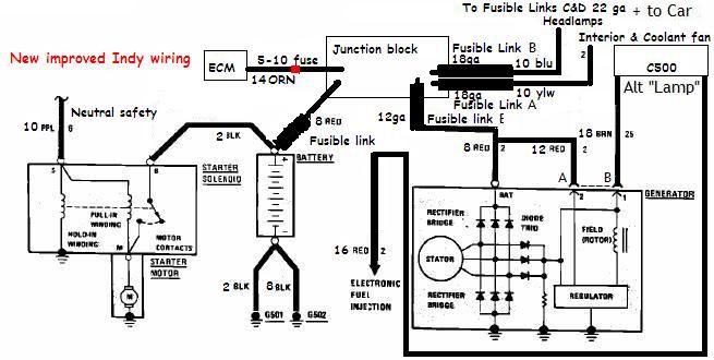
Ok I have been reading extensively through the cave... wow... 3rd time and I think I'm forming a plan. Will need some feedback. I'm redrawing my new 84 wiring schematic using the one listed in the cave. I had no clue the wire sizes and link sizes we actually there on the schematic... UGH! Its all becoming clearer. I wish I would have known that single fact earlier. THANK YOU ORGE!
So based on what I have decoded the previous owner did not do too bad on the replacement size wires... but the lack of any fusible links... ok wow! But one big question I have on the 84 diagram...
Is the circled image not a fusible link? If so... what size and how should I incorporate this into my new wiring. Splice it off another line or run a separate one to the junction block? It shows to be spliced off the Alternator output line. Seems dangerous to me...
That leads me to my next question... I always thought the idea with wiring is to never run anything directly off the alternator. That all power must come through the battery first as a buffer. Supposedly this is the danger of running a car w/o a battery (removing once started). There is no voltage spike buffer in place (battery) so you can fry the ECM very easily. That being said would one not want to run the alternator output back to the battery and not to the junction block directly? Or is that why there are 2 posts. One for the big voltages and the other for the smaller???
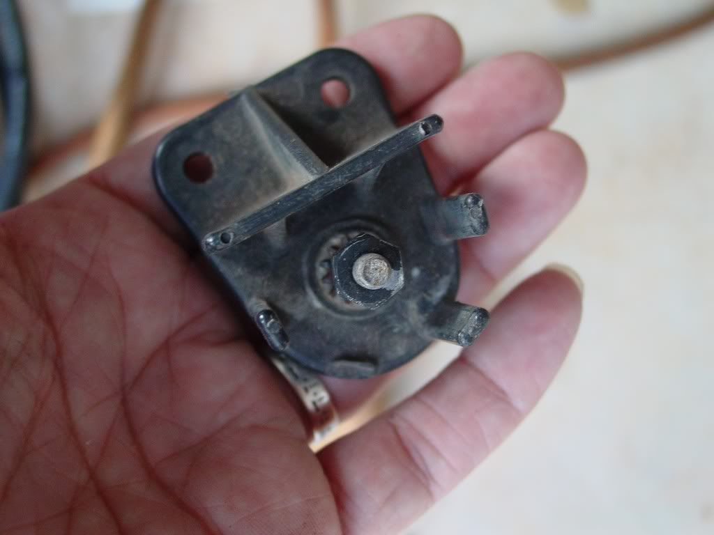
Circle link is link F and runs ECM memory and Should be intact. Is ECM "reset" circuit and i think is on engine at valve cover area. Look for same kind of connector as O2 sensor.
No... don't over think this... Just get a headache. And I add/delete/move things in some diagrams in cave articles so watch it...
Alt and Battery together runs everything. All devices can be on/near either and still be in circuit to buffer etc
85+ box uses 2 screws for easier to make car at plant... 1 or 5 screws doesn't matter to circuit. And 2 screws are Not connected to each other. Alt has custom 2 holes crimp and bolts to both of them.
Thank you again. I got worried there was another link the previous owner deleted. I was wondering it it was G... ugh
I have uploaded and been looking at the 86 diagrams from the manual link you gave me. Between it and the 84 diagram from your site, I think I have a pretty good idea what i need to do and what is what. I will post my rewire plan before I physically do it do be sure I have everything interpolated right.
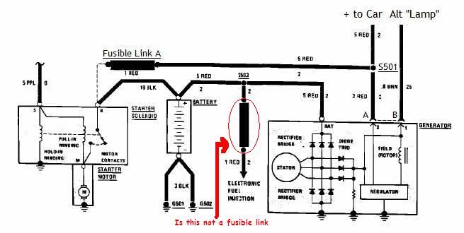
The crazy thing is the previous owner moved some wires around. Instead of the two wires and a battery line coming off the starter I have alot more. I would not be so worried if the links were still intact. I found my old thread from 2 years ago (before I parked the car) where I detailed what wires I found on my starter. I was trying to get help IDing them. Thanks to the diagrams I'm much closer to figuring them all out... finally!
Large stud: 1. battery cable (4 gauge) 2. red 10-12 gauge running to the alternator output 3. red 10-12 gauge running through the firewall (headlights?) 4. red 10-12 gauge mystery wire... need to track it still... 5. orange or tan 14-16 gauge. runs to the box of wires on the driver side and passed into the interior (ECM?)
Small stud purpleish wire (ignition)
I will verify everything tomorrow or Thursday night. Going to get some supplies as well... new wiring all around... battery cable and the rest of the power system in the bay. New fusible links for every circuit. A tube of dielectric compound is coming home with me too.
With the ogre you're in good hands, follow his advice. It was suspect that the stock alternator couldn't keep up with stock demands it was designed to handle. I figured you had a short/parasitic drag somewhere. btw. some movement of voltage gauge with blinkers is normal. The dimming of the headlights is not.
I have learned so much thanks to the Ogre! I think I might be able to fix my little car now! Yeah! Pm helped so much!
The turn signals would pull the car a good volt, even two... sometimes it was enough to kill the car. It was so bad I would keep it in neutral and rev it up at stop lights at night... even kill the radio and temp controls
Now the individual wires that are not going to the alternator... I will refer to them with the same numbers I detailed in my prior post
quote
Originally posted by redraif:
Large stud: 1. battery cable (4 gauge) 2. red 10-12 gauge running to the alternator output 3. red 10-12 gauge running through the firewall (headlights?) 4. red 10-12 gauge mystery wire... need to track it still... 5. orange or tan 14-16 gauge. runs to the box of wires on the driver side and passed into the interior (ECM?)
Small stud purpleish wire (ignition)
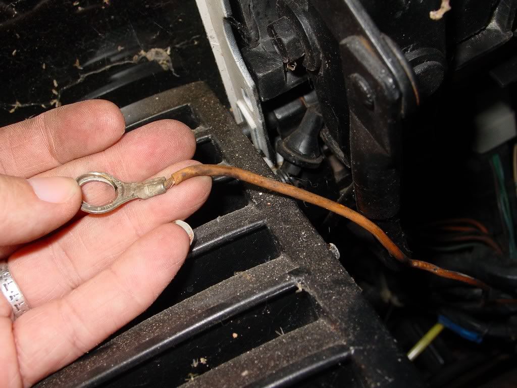
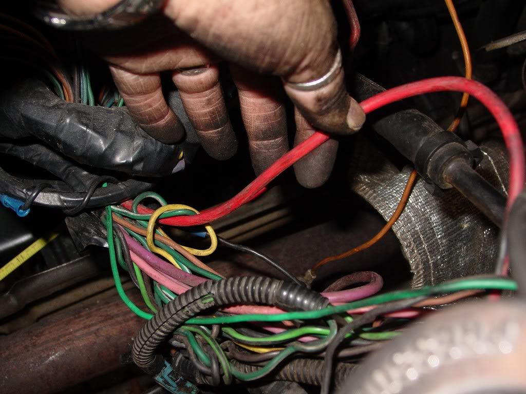
5. Now tracing the wires... the smaller of the group... ORANGE
He traces back to the ECM pass though in the firewall
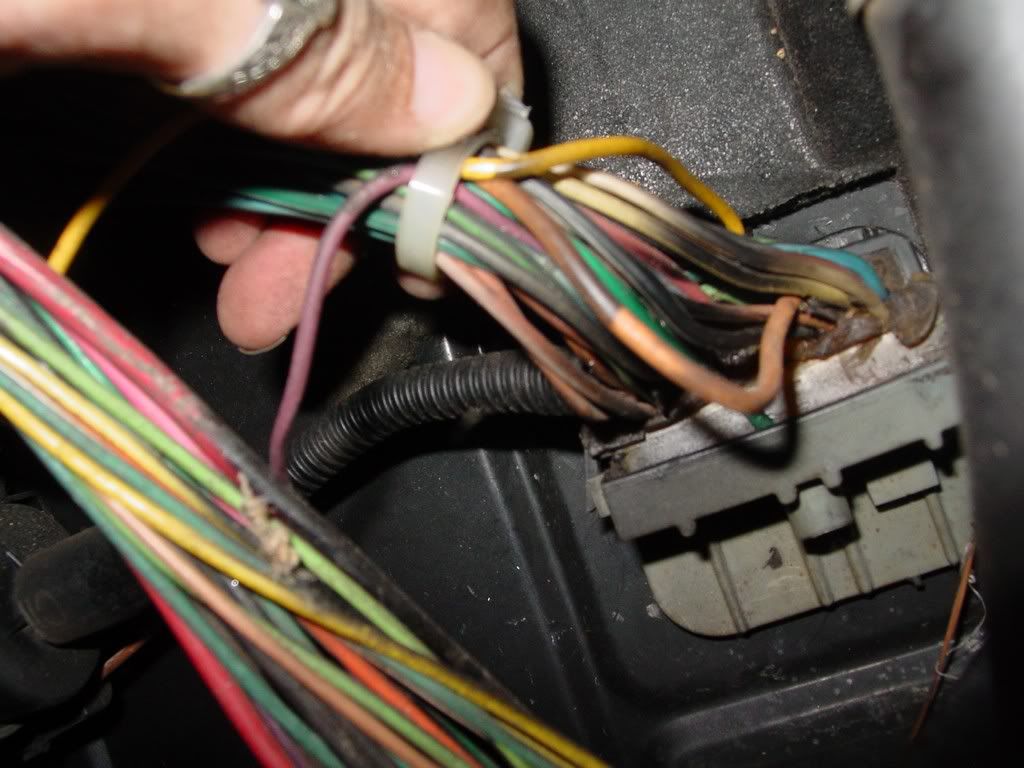
3. One red mystery...
Traces back to the box of wires... not sure what you call this...
[This message has been edited by redraif (edited 08-17-2011).]
Large stud: 1. battery cable (4 gauge) 2. red 10-12 gauge running to the alternator output 3. red 10-12 gauge running through the firewall (headlights?) 4. red 10-12 gauge mystery wire... need to track it still... 5. orange or tan 14-16 gauge. runs to the box of wires on the driver side and passed into the interior (ECM?)
Small stud purpleish wire (ignition)
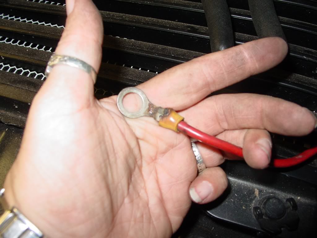
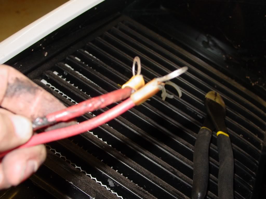
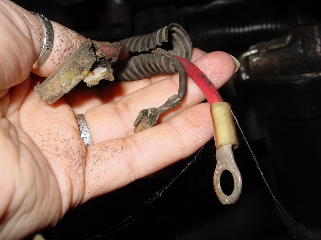
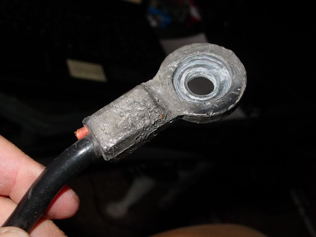
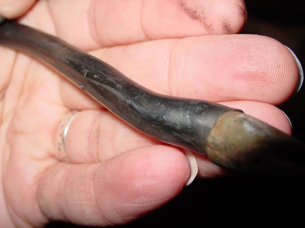
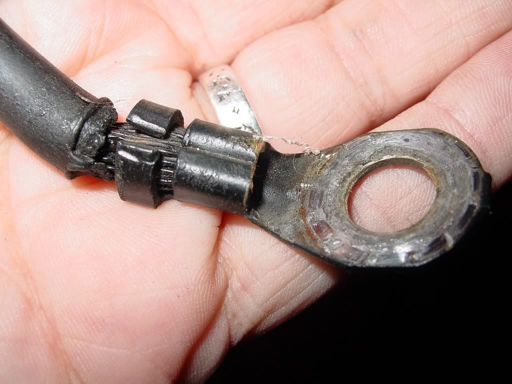
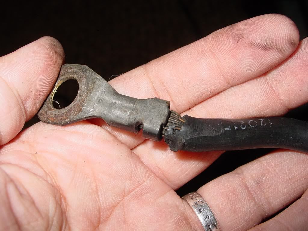
2. The other red wire traces to the alternator output bolt on the alt... here are both ends
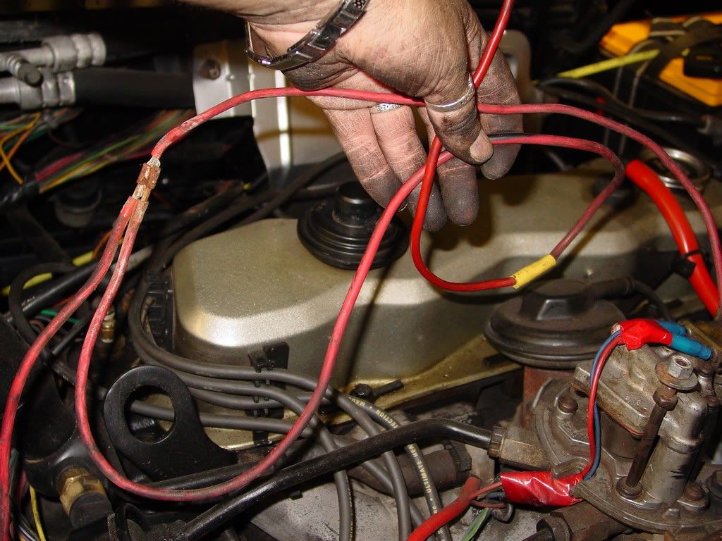
4. Now the last red wire... the one I could not figure out before... it goes to the alternator's plug in line...
it has the spliced line that leads to the box of wires also...
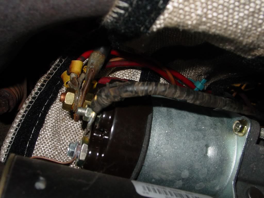
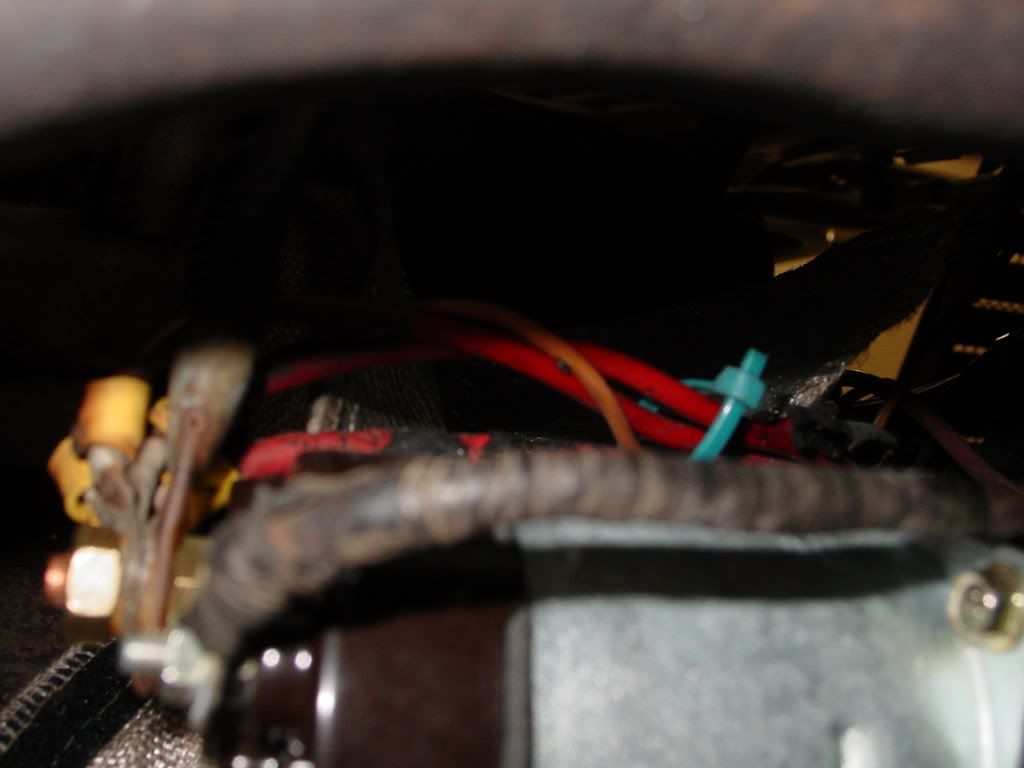
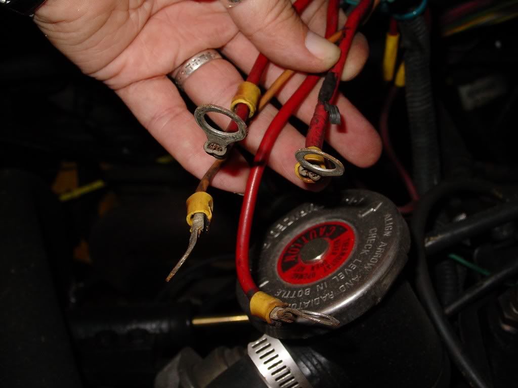
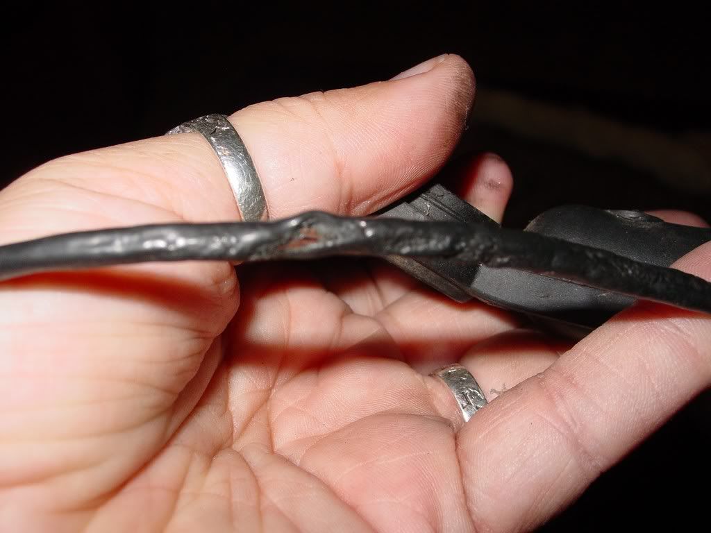
Here are all three connections from the alternator
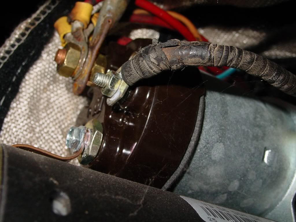
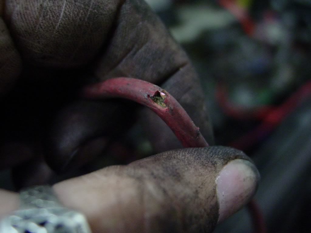
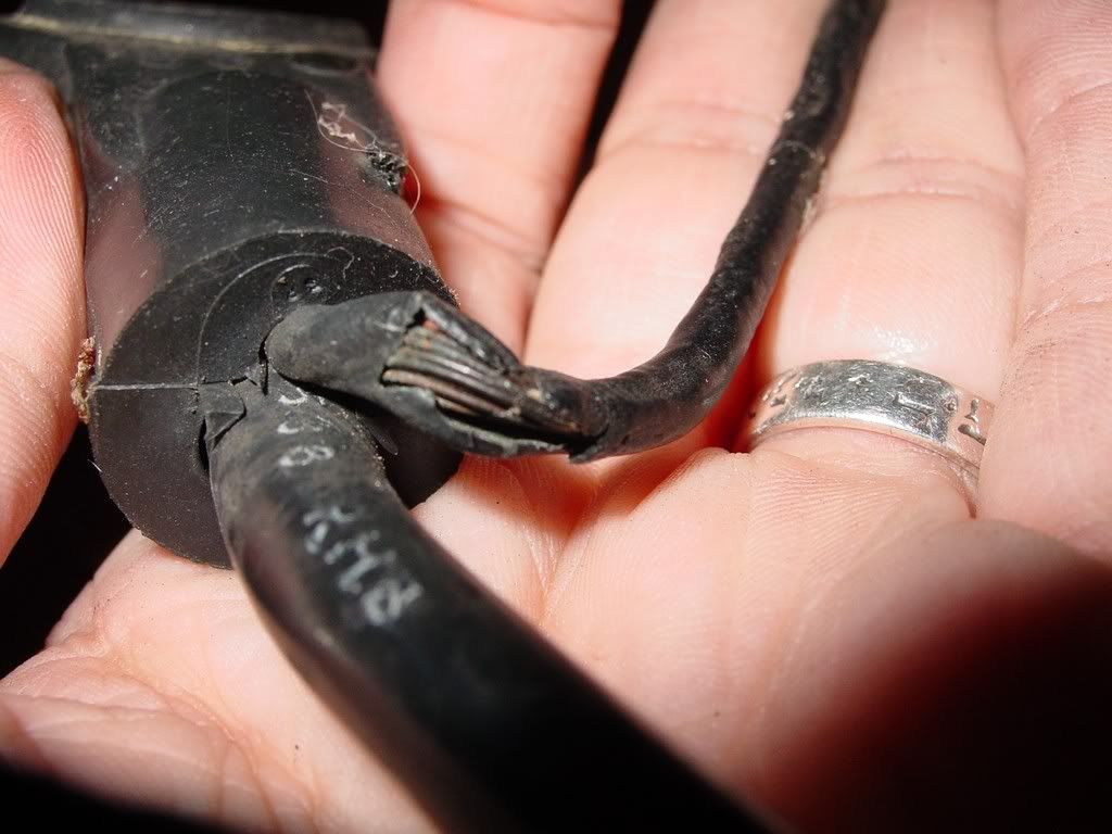
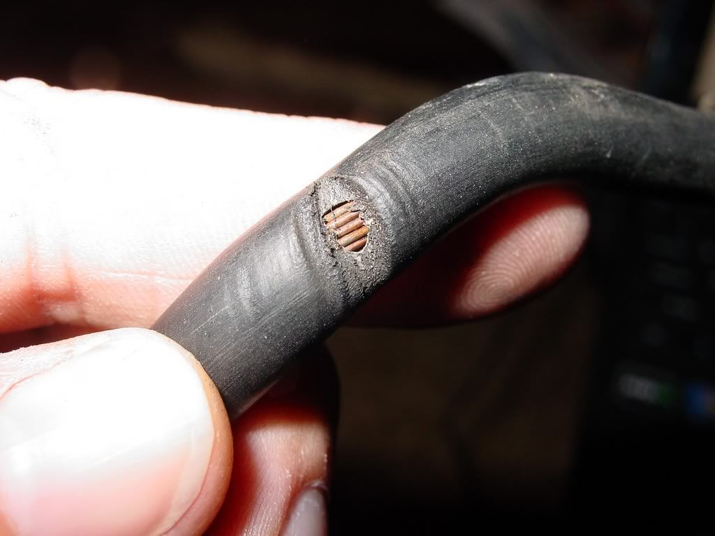
Now the close ups... on the spliced line on the alt side
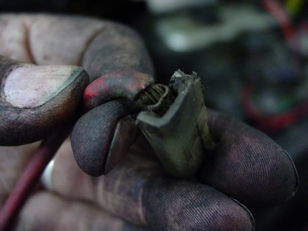
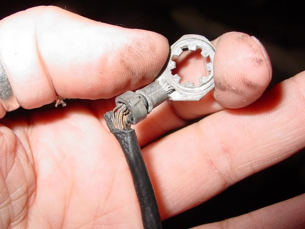
Now the actual alt plug in weather pack... ugh!
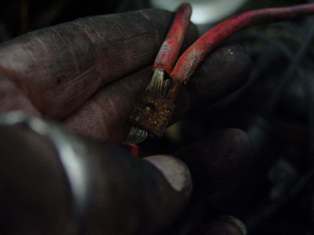
The splice
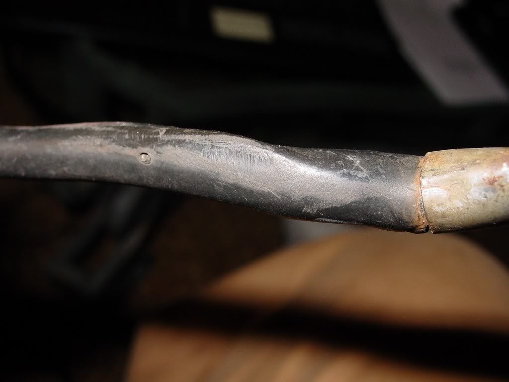
They all look like they have water/corrosion damage!
[This message has been edited by redraif (edited 08-17-2011).]
Not a single fusible link to be found anywhere! The odd thing was that the line that runs to the alternator output is supposed to have the injector wire spliced into it with a fusible link... Mine does not. The injector wires both run to the ECM plug in at the firewall. no link... WTF?
My other frustration... I went to go get fusible links... autozone and advance only carry 14 gauge links... no mention if they are to protect a 14 gauge or if they are 14 gauge (AWG) UGH! So I will try O'Reilly and NAPA.
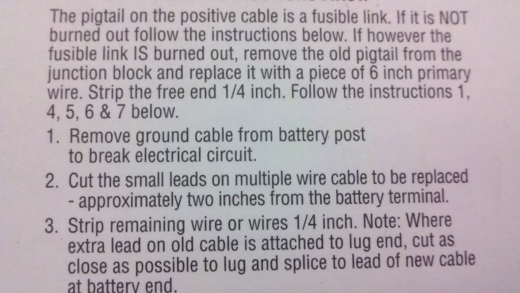
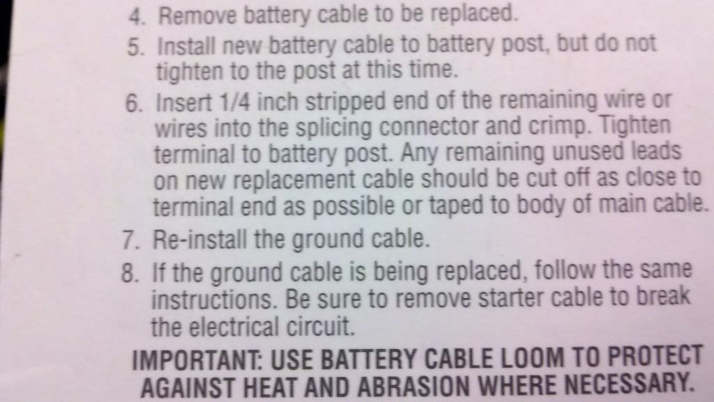
Hard to find the side post battery cables as well. Tons of top mount! The odd thing is the small aux wire off the cables. They are so small. Are they the fusible links themselves and you just add in your own wire to the butt connector?
And no decent distribution blocks guess I will use mine from the junkyard.
[This message has been edited by redraif (edited 08-17-2011).]
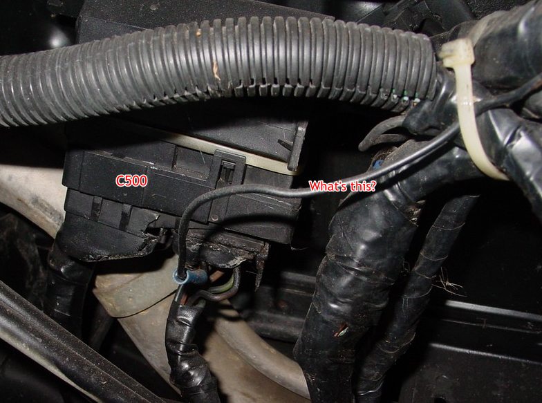
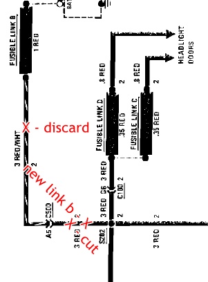
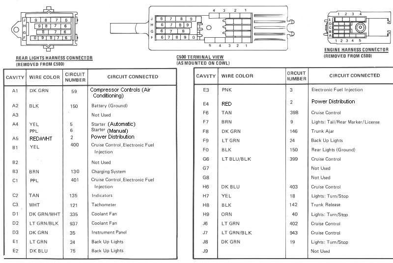
1 Red wire goes to C500 A5. What goes to black wire at C500? Need to bypass C500 because C500 can't handle amp in this circuit. (85+ fixed that.) Save discard wire and C500 pin to fix black wire. Black wire I guessing goes to Pink wire, C500 E3, and Ignition Coil. (84 says doesn't use link H but can add it...) See term access in cave and service manual... tells you how to remove C500 pins and Map for C500. C500 pins is marked too.
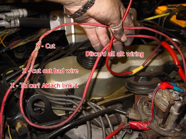
Cut out all alt wiring. Attach link A to red wire goes to rest of car. Make new alt harness. get new side plug at parts store. Common plug to need. attach link E. Solder splice output to A pin connection Or if side plug has long enough wires, crimp both output and A wire in one crimp ring.
Option on Orn wire... Use a weather poof standard fuse holder, not a fuse link. Fuse 5-10 amp should work. Fuse give you a easy reset when ECM codes pops up in future.
Your "distribution box" is fine. Mount near C500 with ECM fuse option.
Battery cables... Most aftermarket has short plane wire, not a link. Only ACdelco has a link and extra wire. Using a Link here isn't needed.
Insulated Crimp uses color code... Use smallest crimp will fit wire. Do not think Yellow will take smaller wire and over crimp with tool... Make a crappy connection...
Coat and pack into grease every crimp to keep water out.
+ is bad then check all grounds too... I bet grounds has problems.
Pm sent
[This message has been edited by theogre (edited 08-18-2011).]
1 Red wire goes to C500 A5. What goes to black wire at C500?
Ok I thought that was the C500... The black wire was cut loose when I got the car at C500. I added the butt connector to lengthen it to find its home. I have to go back and look up what we found it to be... Made a thread... I will search it and get back to you on this.
quote
Need to bypass C500 because C500 can't handle amp in this circuit. (85+ fixed that.) Save discard wire and C500 pin to fix black wire. Black wire I guessing goes to Pink wire, C500 E3, and Ignition Coil. (84 says doesn't use link H but can add it...) See term access in cave and service manual... tells you how to remove C500 pins and Map for C500. C500 pins is marked too.
If the c500 can't handle the amps in the headlight curcuit with the 12 ga wire, should I beef it to a 10ga when I bypass the c500? Also do I need to worry about the other red 10ga going to the C500 (fusible link A) Since I'm cutting out the alternator from this curcuit anyway and the wiring is so bad, should I bypass the c500 as well on fusible link A "to car line"?
quote
Cut out all alt wiring. Attach link A to red wire goes to rest of car.
Make new alt harness. get new side plug at parts store. Common plug to need. attach link E. Solder splice output to A pin connection Or if side plug has long enough wires, crimp both output and A wire in one crimp ring.
By side plug do you mean the stereo style add in side plug lug. I have a ton of them! So attach link E to the battery or the Junction block I will be adding? I'm planning on replacing the whole power curcuit that is suspect. I have all new 10 gauge wire in different colors. The originals and previous owner splice ins were all at the starter by the exhaust and it all looks like poo. I'm running 8 ga as the new alternator output line and splicing in a new short 12 ga atl line off the alternator plug. I have a new plug to replace my broken one. Just going to repin into replacment connector.
quote
Option on Orn wire... Use a weather poof standard fuse holder, not a fuse link. Fuse 5-10 amp should work. Fuse give you a easy reset when ECM codes pops up in future.
Your "distribution box" is fine. Mount near C500 with ECM fuse option.
Awesome... I have plenty of these at the house! I will add the fuse option
quote
Battery cables... Most aftermarket has short plane wire, not a link. Only ACdelco has a link and extra wire. Using a Link here isn't needed.
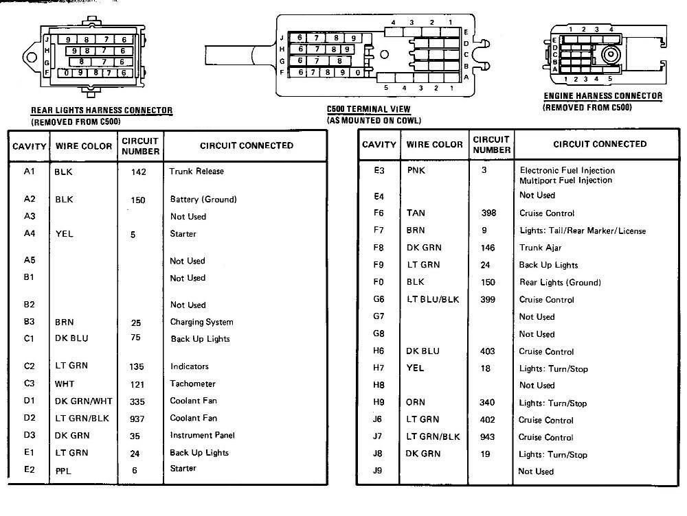
I'm buying new battery cables positive and negative from Autozone in a 2 ga. Here are the pics of the directions that made me think they are links as well... so I'm not sure I have a choice.
quote
+ is bad then check all grounds too... I bet grounds has problems.
Pm sent
I replaced and added ground straps first then started on the power side. Only thing I did not do was the battery ground. I'm doing it this time!
Originally posted by theogre: 1 Red wire goes to C500 A5. What goes to black wire at C500? Need to bypass C500 because C500 can't handle amp in this circuit. (85+ fixed that.) Save discard wire and C500 pin to fix black wire. Black wire I guessing goes to Pink wire, C500 E3, and Ignition Coil. (84 says doesn't use link H but can add it...) See term access in cave and service manual... tells you how to remove C500 pins and Map for C500. C500 pins is marked too.
Bypass c500 in link A will help to... I didn't see the section of power dist diagram Just cut out C500 (E4 i think), same as new link B, and add new link A. Should be enough length to reach new dist box.
Save enough wires and C500 pins to fix other things.... Don't junk C500 pins...
Battery cable... If your cable does use fuse link then not a problem... just crimp more wire to reach dist box.
All new wire/links go to dist/junction box. Nothing goes to battery except battery cables.
Side plug gage can be small... plug only for alt's regulator to monitor alt's output volts. No need to use more wire gage then stock plug.
8ga to alt? 10 ga is max for crimp tool above. tool can't do 10 ga wire + wire A either... Try http://www.posi-lock.com/ to splice Wire A to output if you want big wire for output.
Use this to wire alt... (from alt sense in cave) or if plug wires is long enough, crimp wire A and output to ring for output. Saves solder etc splice.
[This message has been edited by theogre (edited 08-18-2011).]
I will slip the alternator sense wire in at the connection of the alternator output.
I will bypass the c500. How do I know what is what on the other side of the c500? I always save the pins... lol... my c500 is chargrilled on one side anyway.... bet that's how I got such messed up wiring from the previous owner
If your going to bypass the stock sense wire you could run a new wire from the fuse box with a light inline. Thats how I ran mine and its working great.
if I understand it right... I'm not bypassing, but making the loop shorter to keep it from failing as easy or at least making a shorter loop to check... like newer style fieros!
Ok I don't have the c500 pin out... guess I will search hope I don't get busted at work... LOL!
Originally posted by redraif: I will bypass the c500. How do I know what is what on the other side of the c500? I always save the pins... lol... my c500 is chargrilled on one side anyway.... bet that's how I got such messed up wiring from the previous owner
Some wire colors will change at C500 and other connectors. Check C500 map (Smaller image above looks correct) and follows circuit diagram to double check map. At least the map will tell you which terminal is which...
Looks like 84 C500 appears to uses bigger terminal for some circuit and If so bigger terminals is fine for most circuits. I would still bypass C500 those two circuits. In Day to Day driving, C500 can deal with amp draw but if there is a problem, like fan gets a short, can overload the terminal in C500.
Jake, He's not bypass sense wire just making sense shorter. Lamp is a different circuit and has nothing do to with sense circuit. Can add a Lamp but car has many problem that needs fixing. (Look at picture showing TBI unit...)
So Napa was closed O'Reilley's had 16 gauge and 14... and a roll of 14. But no 18 or 12... UGH! Looking like I might be having to order them from somewhere?
Waiting on a guy to come look at our dock for a rebuild. Would do it myself, but not very water worthy with my broken foot. Was quite funny crawling up and around the car while it was on jackstands with the foot! LOL! I find I tend to crawl in and sit in the trunk!
quote
Originally posted by theogre:
Some wire colors will change at C500 and other connectors. Check C500 map (Smaller image above looks correct) and follows circuit diagram to double check map. At least the map will tell you which terminal is which...
Looks like 84 C500 appears to uses bigger terminal for some circuit and If so bigger terminals is fine for most circuits. I would still bypass C500 those two circuits. In Day to Day driving, C500 can deal with amp draw but if there is a problem, like fan gets a short, can overload the terminal in C500.
Ok I will still bypass it. I want to be safer. I plan to check things really good by the charred end... figure verify the maps to be sure what is what. while I'm in there, should I replace the purple neutral safety/ignition line at the C500 to the stater. I works as the car started, but I did have the intermittent start issue...
quote
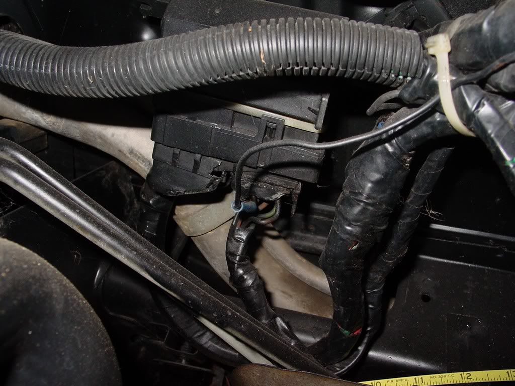
Can add a Lamp but car has many problem that needs fixing. (Look at picture showing TBI unit...)
You mean this... LOL
Yes the deeper I dig the more scared I become
[This message has been edited by redraif (edited 08-18-2011).]
So I took the c500 loose from the firewall and took it apart... now I just have to fish out my wires to bypass... Going to clean, blow out and use the dialetric before it goes back together. I also think I have enough line to move it over to the batter side. That will be better.... everything all in one spot!
Just finished at Napa. Oh dear lord the waterproof connectors are so expensive, but I got them! Also got some 10 gauge waterproof butt connectors for my C500 work around on the headlight and interior lines. Also got connectors for the dist block.
I got some 18 gauge fusible links and some 12 gauge fusible link wire in a spool. Could not find the 22 gauge fusible links though... they only had 20 gauge.
But those can wait... I have the important ones now! Fingers crossed I will have my little guy back together soon.
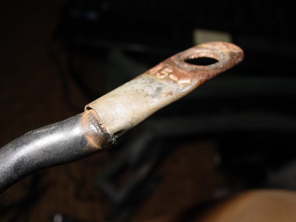
Also tried to buy a 2 GAUGE battery cable for my ground. Non-existent for a side post mount. The guy made one up for me.
Darn droid and its spelling changes
[This message has been edited by redraif (edited 08-20-2011).]
Ok got the old battery cables off and compared them to the new ones. Ok and wow my negative cable was a bigger wreck then I thought. Positive was a bit suspect where it connected to the starter.