Like the title says how do you wire in the 4T60E in to the Fiero Mine 87 GT Auto In the process of doing the 4.9 swap trying to get the car on the road in 2 days. Anyone have a step by step process? Any help please. Micky Moose has been great helping me on the main wire harness but the says that he is not familiar witht he 4T60E.
IP: Logged
05:43 PM
PFF
System Bot
josef644 Member
Posts: 6939 From: Dickinson, Texas USA Registered: Nov 2006
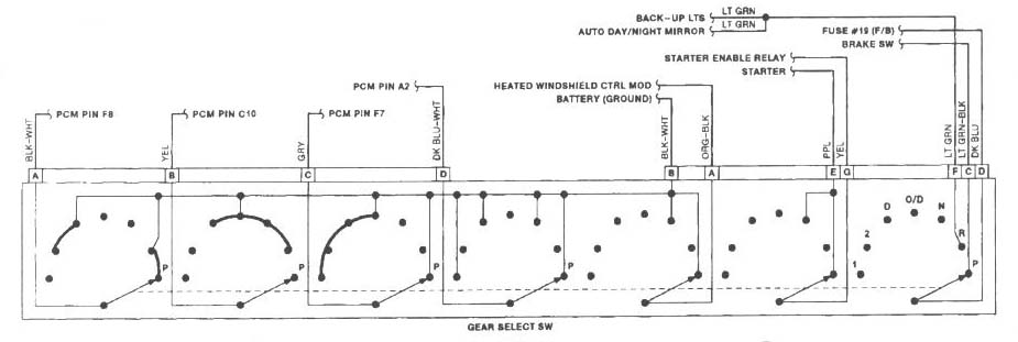
I have done this, and used his wiring diagrams. The neutral safety switch and transmission range switch connector need to talk to the ECM. First 4 on the left is the range switch, other side is the neutral safety switch. Do not worry about the heated windshield and day /night mirror. As I recall did not connect the brake light signal either as I didn't need to have my foot an the brake to move the transmission out of 'PARK':
There is a round plug in connector with 6-7 wires depending on your transmission and harness. If you just follow his instructions you will be good to go. There was a color change on some of the harnesses of the wires. So you need to know which year harness, and 4T60E your are dealing with. Transmission wiring is it the bottom of this page. IIRC the sockets were pinned the same, but wiring colors were different. So socket would over ride wire color. You need to verify this first. The VCC Brk Switch will feed your round transmission socket threw C203 R. If your car was a factory automatic, this wire is already there on both sides of the C203 connector. This is really easy and nothing to be afraid to do. Mine worked the first time I got it on the road.
You are gonn love this swap. -Joe
P.S. All these diagrams above are right from M_M's wiring thread, and all credit is to him.
IP: Logged
06:47 PM
Jun 21st, 2011
bristowb Member
Posts: 745 From: douglasville,georgia,usa Registered: Oct 2009
Can someone please explain to me what the transmission diagram and the bottom of the quoted page means in Layman terms. I do not understand what all the lines mean or how they connect. I understand one side(right of page) is the PCM but what is the other side and the letters and numbers in the middle mean. The VCC switch at the top?
This is Micky Moose wiring diagram from his post.
IP: Logged
09:47 PM
phonedawgz Member
Posts: 17108 From: Green Bay, WI USA Registered: Dec 2009
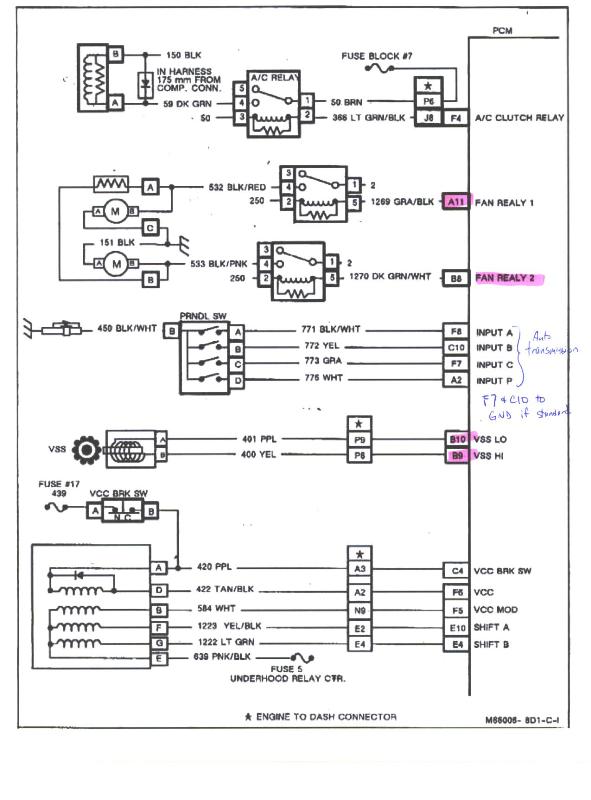
The VCC switch at the top is equivalent to the TCC switch on a automatic transmission Fiero. Power is sent to Pin P PURPLE of C203 whenever the key is on and the brake switch is not depressed. So you would hook pin P to A of the transmission and C4 of the PCM
The other marked wires of the PCM need to go to the correct marked locations of the transmission. The transmission is controlled by the PCM.
Finally Pin E of the transmission needs to be connected to a switched power source. If you powered all your injectors off of INJ1, then you can use INJ2 (C203 K) to power your the transmission. You may need to increase the fuse size of INJ2 to do this.
The letters in the middle are a connector that is electrically between the two. Your swap most likely won't use that connector.
[This message has been edited by phonedawgz (edited 06-21-2011).]
While these are about as self explanatory as they get, I will do my best to clear some things up for you.. Hopefully.. For starters, the first image in Josef's reply is only showing you/focusing on one thing - the Gear Select Switch. Ignore all the dots, lines, dashes, etc inside the big rectangle, those are the internal workings of said switch. Concern yourself with the 'pinout', the wire color, and that wires specific destination. This is telling you how that switch is wired, plain and simple.
For example: The pinout of this switch, from left to right, is A B C D followed by B A E G F C D with wire colors (just a few, in order, left to right) BLK-WHT, YEL, GRY DK BLU-WHT and destinations (again, just a few in order from left to right) PCM F8, C10, F7, A2.
So in 'laymans terms' this is telling you that the black and white wire in pin A of the gear select switch is supposed to go to pin F8 in the PCM. As Joe mentioned the wire colors apparently changed, but the pinouts are the same. I can't confirm this one way or the other as of right now, but I would take his advice. In that case, wire it according to the pinout and if the colors don't match I wouldn't worry about it - unless it doesn't work of course.
Based on the information above you should be able to figure out that the next image is just a broader diagram similar to the first. The right side is the PCM, on the left are the various components and the middle (where applicable) is the engine to dash connector. Again, ignore the lines, curly q's, dashes, etc inside the rectangles. Focus on the wire color, pinout, and destination. It really is that simple :P
IP: Logged
11:55 PM
Jun 22nd, 2011
bristowb Member
Posts: 745 From: douglasville,georgia,usa Registered: Oct 2009
OK last 3 wires on the first diagram all the way to the right of the diagram are 3 wires. I assume the is the 7 pin SQUARE plug. Wire C goes to brake switch HOW? Wire D goes to Fuse, HOW? Wire F goes to back up lights? ( in the original Micky Moose post on the C500 Connector ther are 3 different back up lights connections F9,C1,E1. Which one do I use?
Everything else is wired correctly because I have the original Caddy harness everything just pluged in. It's the connecting to the C500 and ALDL and the C203 I have had the hardest time with. I thank you all so much for all your help.
[This message has been edited by bristowb (edited 06-22-2011).]
IP: Logged
09:04 AM
phonedawgz Member
Posts: 17108 From: Green Bay, WI USA Registered: Dec 2009
When you look at the engine plug - it doesn't plug into pin F9. The rear light harness plugs into F9
So the two wires you need to use are C500 C1 - Dark Blue to Pin D of the Gear Select connector - and C500 E1 - Light Green to F of the Gear Select connector
Pin C of the Gear Select connector is not used on a Fiero.