I'm at that point where the wiring will get started very soon on my 3400 swap into my 86 GT 4 speed and I just don't know where to begin. I did find Darth Fiero's pinout tables on the Sinister Performance website so that's a great start. Basically should I hook up the OEM harness to the motor then go from there? Should I follow each and every pin or just the ones that need to be changed? Also for the Fiero C203 and C500 connectors, these I cut off the stock Fiero harness but is there a way to know which stock wires I need to keep intact? So I have the stock Fiero manual transmission and the only wires I'll need from the Fiero harness are for the speed sensor, anything else I need? I'm just not sure so any input would be most helpful.
IP: Logged
02:25 PM
PFF
System Bot
phonedawgz Member
Posts: 17108 From: Green Bay, WI USA Registered: Dec 2009
Pull ALL the pins from the ECM connectors USING THE PROPER TOOL. If you force them out you will ruin the PCM plastic shell plug and perhaps the metal connectors also. The stock FIERO type metal connectors can be released using a paper clip. I'm not sure what your PCM connectors look like. Label the pins as you take them out to help double check when you reassemble them.
Label ALL sensor connectors on the donor harness. Do both the ones you plan on re-using and the ones you don't.
Disassemble the donor harness wire loom and tape. Now remove each sensor connector from the harness leaving the wiring to the ECM pins in tact. Coil up each after you disassemble them and toss them in a box. Any splices you get to will need to be cut Cut the 'sensor wire' at the splice so the sensor "long pigtail" doesn't have the splice still attached to it. After you have the sensors/injectors/ect all coiled up and in your box cut any other splices and coil them up also.
Now undress the Fiero haress. The things you want to save are C203 and C500. So just like the other harness sensors keep as much wire on C500 and C203 as possible. The VSS can be left on tthe C203 pigtail. Depending on what alternator you are using you may need the alternator connector from the Fiero harness.
Figure out the path and length of the wires to C500 and C203 that you will need. Lay them out on a 2x4 attached to the engine (on a stand). Plan the path your harness will take. Put partially closed tywraps at junction points to keep your wires together as your harness forms. You will need to thread the wire through the tywraps as you put the wires in. Start with the farthest sensors/injectors and work towards the ECM. If you are lucky your wires will be long enough on a number of sensors and they can just be slid back into the ECM connector. Wires that are not long enough will need to be spliced. Any wires to C203/C500 will need to be spliced. Put all the connectors back onto the engine connecting them as you go. Some power wires, sensor 5v wires, and ground wires will need to be spliced inside the harness. You saw that when you took your other harness's apart. Any added spliced wires should be of the same color to aid future troubleshooting.
Finally you need to add the 'extras' The fuel pump relay. The AC relay. If you ever think you are going to sometime swap to a 5 speed you might want to add a reverse light switch connector.
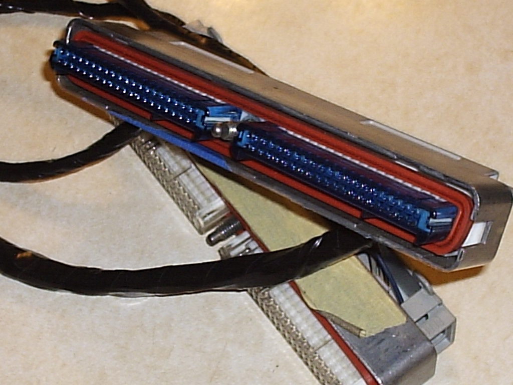
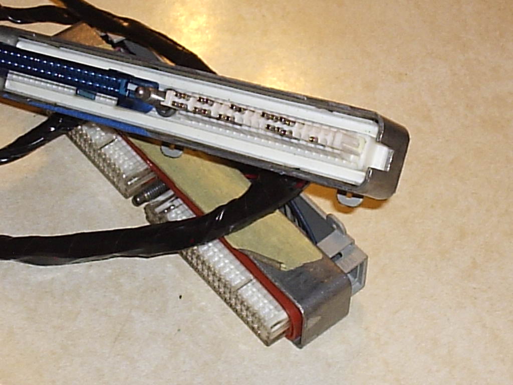
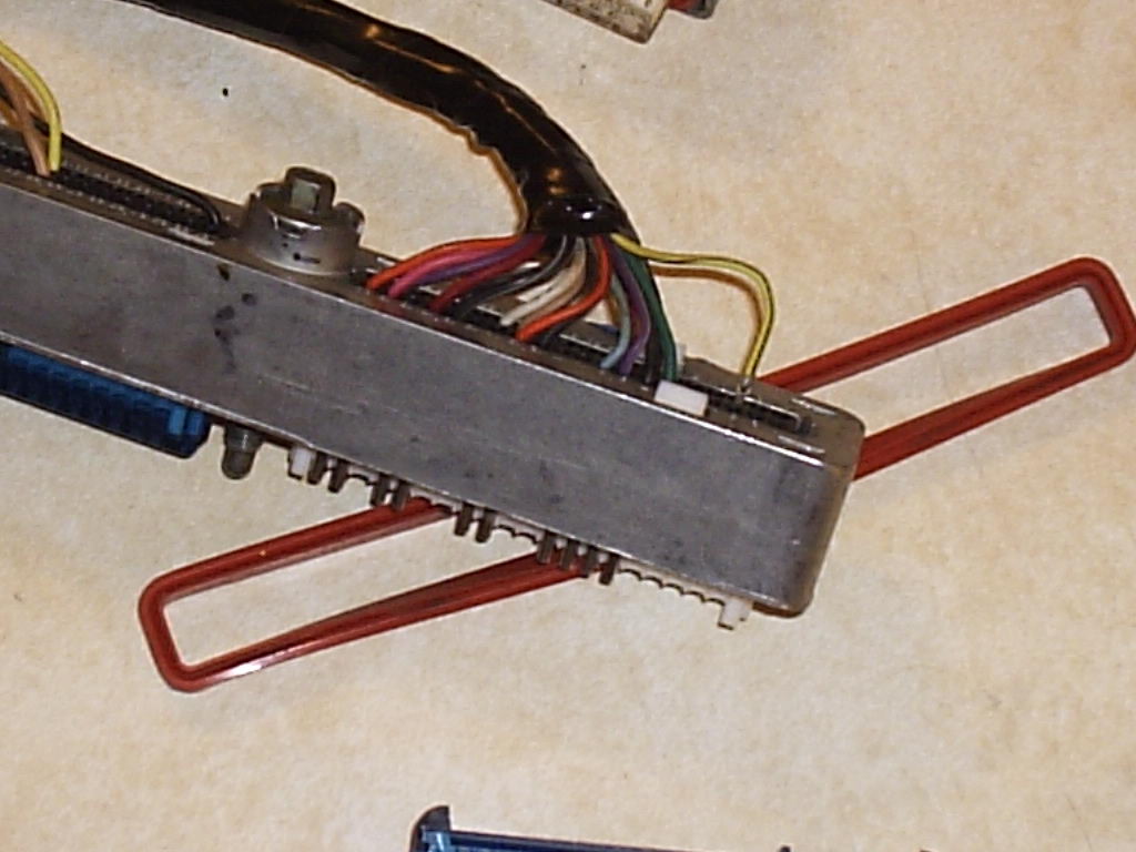
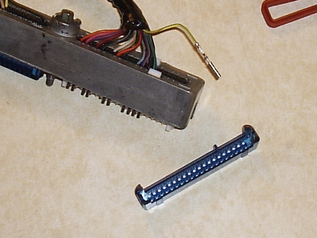
So you have the blue and clear PCM connectors? The blue/clear cover comes off - A tab on each end of the blue/clear cover will release it and you can pull it off. Then on each pin push it away from the center plastic. Then with a small screwdriver lift the finger of plastic. Now pull the wire out the back. The pin WILL be held in if the pin is against either the center or the finger.
Sorry I couldn't take a picture of me pulling the pin away from the center bar and also pulling the finger back. The pin can't be against either or it will be held in the connector.
[This message has been edited by phonedawgz (edited 04-19-2011).]
IP: Logged
11:11 PM
May 3rd, 2011
KaijuSenso Member
Posts: 911 From: Westland, MI Registered: Jan 2007
Ok got basically the entire 3400 harness broken apart and labeled but I had a few questions based on the Sinister Performance pin out chart. I labeled all of the wires I had in the connector but there are a couple missing.
From the C1 Blue connector I am missing pins:
12- coolant temp sensor ground 13- MAP sensor ground 31- EGR pintle position ground (Deleting EGR so no issue) 61- TPS ground 71- Traction Control Desired Torque Input (delete so no issue) 75- Engine Hot Warning Lamp Control
From the C2 Clear connector
8- Tach input (delete) 9- Traction Control (delete) 35- Ground for AC pressure and Trans Temp 70- 24x Crankshaft position sensor ground 74- 24x crankshaft position sensor power supply 77- boost control solenoid control circuit (says *optional* thus I assume I don't have it because it's for boosted cars?)
plus for this C2 connector I have one wire that isn't in the pinout chart
36 and it's Gray
The computer is Serv. No. 16236757 from a 98 Monte Carlo 3100 and the Harness should be a match (i'll double check with who I bought it off of)
Does anyone know why these wires are missing and if I need them? The harness was definitely not tampered with, these wires were literally not in the connectors.
IP: Logged
07:15 PM
phonedawgz Member
Posts: 17108 From: Green Bay, WI USA Registered: Dec 2009
So on your sensor grounds, what were those sensor's ground wires wired to?
For the HOT pin, you will need to add a wire to it and run that to your TEMP light.
Have you reversed your TEMP light and TEMP gauge circuits yet? If not you should at this time. Assuming you have, then you would connect the wire that was your temp gauge, but now is your temp light to the temp light pin on your PCM.
IP: Logged
08:13 PM
May 4th, 2011
KaijuSenso Member
Posts: 911 From: Westland, MI Registered: Jan 2007
The grounds (from what I can remember...) where split between 3 major sources. Two of which are attached to the little fuse box wired into the harness, one of these two also included the 4 PCM ground pins. These two also lead out to engine block grounds. Then there was a group of seven ground wires that went into a large connector (A-L by 1-5), not sure what it's called, These grounds don't lead out anywhere. Also connected here is the thick purple starter wire and a thick red wire which leads to the previously mentioned small fuse box.
The grounds listed above can be wired to any engine block ground then?
I cross referenced another pinout chart on the Sinister Performance website for the 3800 that said it worked with the same # PCM as mine and it had pin C2-36, gray, listed as the change oil light and said delete so it looks like I'll be ok there.
Is it ok to just add the pin for the Hot temperature light? Will the PCM automatically recognize it if it didn't have it originally?
IP: Logged
01:03 AM
phonedawgz Member
Posts: 17108 From: Green Bay, WI USA Registered: Dec 2009
On the sensor grounds, run a wire back from the sensor in question directly to the pin. To keep these clean from any electrical noise it is best not to common them to a joint ground, or to use the engine block as ground.
Run your purple wire from C500 directly to the starter solenoid
You don't have a 24x sensor on your crankshaft?
You should have some wires that do run directly from the PCM to grounds on the engine.
Yes drop the oil change light
Yes add the temp light pin/wire. No the PCM won't just automatically sense it. If your PCM didn't have it programmed into it, when it is flashed to the new program it should be added. If your PCM did have it programmed into it before then it will work without programming.
IP: Logged
06:34 AM
KaijuSenso Member
Posts: 911 From: Westland, MI Registered: Jan 2007
I was told by the guy doing my tuning not to try adding pins to the PCM because the 98 monte carlo 3100 pcm isn't set up for it. I would need to swap to the Grand Prix PCM (which looks like what the pinout chart for the 98 3400 is) and I think it would be easiest to stick with the PCM that matches the harness. If the pins were not necessary for the monte carlo i'll do without them the best I can.
Sadly now that I cut all the splices, I'll need to figure out where they go...the grounds will be the only easy ones.
Also about the Fiero C203 and C500 connectors. I cut each of the connectors off with in theory as much wire as I could. I'm just curious now, do I plice every single one of the wires on these two connectors to something else for the new motor? Are there any wires which won't be used at all?
IP: Logged
08:34 PM
PFF
System Bot
phonedawgz Member
Posts: 17108 From: Green Bay, WI USA Registered: Dec 2009
So your tuner is saying that a Serv. No. 16236757 PCM used in the 3800 and the Serv. No. 16236757 used in the 3400 is different that the Serv. No. 16236757 used in the 3100?
Hmm
IP: Logged
10:25 PM
KaijuSenso Member
Posts: 911 From: Westland, MI Registered: Jan 2007
That was my thought too, odd, but I think it's more along the lines of the actual tune on the computer and not the hardware itself (obviously because the hardware was shared between platforms)
IP: Logged
10:58 PM
May 5th, 2011
KaijuSenso Member
Posts: 911 From: Westland, MI Registered: Jan 2007
C1-20 battery positive voltage, connect to fused (10 amp) battery power feed: what is this?
C1-55 4000 ppm VSS output, connect to any device needing a 4000 ppm VSS signal: I don't think I need this wire because I'm using Fiero tach with Fiero 4 speed manual?
C2-3 Fuel Pump relay control, connect to fiero fuel pump relay: where is this located?
C2-39 AC compressor clutch relay control, connect to fiero AC clutch relay (if used): using AC so where is this fiero relay?
For the Fiero VSS, do I splice the wire between the pins to the PCM as well as straight to the C203 connector?
IP: Logged
12:50 AM
phonedawgz Member
Posts: 17108 From: Green Bay, WI USA Registered: Dec 2009
C1-20 battery positive voltage, connect to fused (10 amp) battery power feed: what is this?
What I have been doing is using the ECM reset/feed wire (the one with the extra connector by C500) and replacing the ECM reset with a fuse holder
quote
C1-55 4000 ppm VSS output, connect to any device needing a 4000 ppm VSS signal: I don't think I need this wire because I'm using Fiero tach with Fiero 4 speed manual?
Correct unless you are also connecting up the GM electronic cruise control (The Fiero vacuum one won't work)
quote
C2-3 Fuel Pump relay control, connect to fiero fuel pump relay: where is this located?
The fuel pump relay is located on the firewall, in the engine compartment, behind the drivers seat, hidden by the air can on a V6
quote
C2-39 AC compressor clutch relay control, connect to fiero AC clutch relay (if used): using AC so where is this fiero relay?
Next to the fuel pump relay
quote
For the Fiero VSS, do I splice the wire between the pins to the PCM as well as straight to the C203 connector?
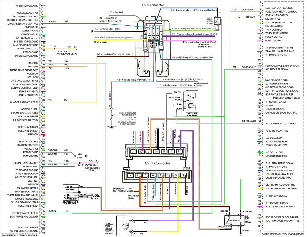
Yes --- Not my diagram - So don't give me credit for it. All I did is 'steal' it.
Here is the fuel pump and AC relay wiring. Note also - this diagram the VSS isn't wired to both the PCM and the speedo. In your Fiero you will have the VSS connected to both.
[This message has been edited by phonedawgz (edited 05-05-2011).]
IP: Logged
10:44 AM
KaijuSenso Member
Posts: 911 From: Westland, MI Registered: Jan 2007
Some applications used one or two grounds or 5v reference circuits coming from the PCM and shared those between multiple sensors/devices (you will find splices in the harness when you remove the loom and tape). That may be why your harness does not have the extra grounds coming from the PCM. You do NOT need to run the extra circuits, just make sure if a sensor needs a ground or a 5v reference signal it is at least sharing a wire from another sensor that is getting that signal.
Items like the hot engine warning lamp control are not used in all applications, so your harness may not have that wire present. You can hook it up if you want to.
The Cam and 24x Crank sensors sometimes got their power and ground directly from the PCM, and other times they got them from another source on the harness (might have been grounded directly to the block and got the 12v+ key-on power directly from the fuse and relay center). You can hook it up either way. If your harness had the cam/crank sensors getting their power and ground signals from a source that did not come from the PCM, you’ll need to make sure those are hooked up correctly in your finished harness/swap.
-ryan
------------------ OVERKILL IS UNDERRATED Custom GM OBD1 & OBD2 Tuning | Engine Conversions & more | www.gmtuners.com
[This message has been edited by Darth Fiero (edited 05-05-2011).]
IP: Logged
03:33 PM
May 24th, 2011
KaijuSenso Member
Posts: 911 From: Westland, MI Registered: Jan 2007
At the power distribution post start with a ring terminal connector. To that attach a weatherproof fuse holder. A 10 amp fuse needs to be in that fuse holder. Run an orange wire from the other side of the fuse holder to C1 Pin 20. While you are there splice that also to pin 16 of your ODBII diagnostic connector.
Weatherproof fuse holder
I put some dielectric gel in the contacts of the fuse holder before I insert the fuse. The rubber cover keeps the water out.
I also like to solder any crimped connections that are exposed to the weather (any ring terminal connections used for ground or at the power distribution posts)
[This message has been edited by phonedawgz (edited 05-24-2011).]
IP: Logged
12:39 PM
KaijuSenso Member
Posts: 911 From: Westland, MI Registered: Jan 2007
Because you mentioned also splicing into the OBDII DLC, if you notice in the diagram you posted, they have the orange/black wire from C203 B spliced between the DLC and the Fuel Pump Relay. Is this an error or does it mean I can skip getting that external fuse holder and just splice the C1 Pin 20 into the orange DLC/ C203 B/ FP Relay wire?
IP: Logged
01:05 PM
PFF
System Bot
phonedawgz Member
Posts: 17108 From: Green Bay, WI USA Registered: Dec 2009
The ODBII connector wire only uses power when a scanner is plugged into the ODBII diagnostic port. So where it is hooked up, or even if it is hoked up at all doesn't matter unless the port is used. It needs to be a constant on 12 power supply. I think it doesn't matter where you hook it up - FP fuse or PCM power fuse.
Can you run the ICM on the fuel pump fuse also? Maybe. Maybe there is enough overhead between the fuel pump load to also run the PCM. But then maybe there isn't enough. Or maybe it will run but later if the fuel pump gets worn it might take more current and then start blowing the fuse. So maybe.
I don't think it's a good idea to take that bet to save the cost of a low cost fuse holder.
IP: Logged
01:27 PM
hookdonspeed Member
Posts: 7980 From: baltimore, md Registered: May 2008
ive come across some issues with wiring my 3500 to a 3400ecu (98 venturevan) i have the full wiring diagram for the venture,a nd some of the pins just dont line up with whats on darth's list, but the ecu is the same for ALL (minus the non gm v6's that were used in gm's) gm v6's in 98, 3100, 3400, 3800, and 3800sc.....
edit: i shouldnt say issues, just differences in 5v and ground references... but as darth already said just do it 1 way or the other.. i.e. my CTS is sharing a ground with the cam sensor as they did in the factory 3500 harness.
[This message has been edited by hookdonspeed (edited 05-24-2011).]