Pennock's Fiero Forum
  Technical Discussion & Questions - Archive
  Wiring a computer-less Fiero - carbed SBC

T H I S   I S   A N   A R C H I V E D   T O P I C
  

Email This Page to Someone! | Printable Version


Wiring a computer-less Fiero - carbed SBC by CowsPatoot
Started on: 03-01-2011 02:04 AM
Replies: 3
Last post by: Arns85GT on 03-01-2011 12:23 PM
CowsPatoot
Member
Posts: 2792
From: Skidway Lake, MI
Registered: May 2007


Feedback score:    (29)
Leave feedback


Total ratings: 84
Rate this member

Report this Post03-01-2011 02:04 AM Click Here to See the Profile for CowsPatootClick Here to visit CowsPatoot's HomePageSend a Private Message to CowsPatootDirect Link to This Post
86 GT, carbed SBC installed with an Archie kit, 4 speed manual

I have been fighting with wiring issues on a SBC swapped Fiero for a while now, and finally decided to take the nuclear bomb approach to killing this mosquito. I get the feeling it was initially installed by someone that was interested in doing the bare minimum work required to start the car, and was then redone by someone that didn't understand the wiring so they made the problem worse. If this was your work, ...I apologize if I offended you but I recommend you don't claim this mess.

Few more details about what I found: It is a carbed v8, but the computer was still installed. The original wiring harness ran through the firewall, then the wires were cut at various points throughout the engine bay to remove the unneeded sensors. Wires were spliced with different color wires in the middle of the harness making it very difficult to trace the wires. There appears to be minimal "aftermarket" wiring in other parts of the vehicle, all of which will be simple to undo.

So...I have completely removed the harness, and drawn out some charts of what I will need. Most of it I am pretty sure of, but I have a couple questions listed at the bottom, all related to the computer removal. Naturally I am open to other input as well, and certainly wouldn't turn down the opportunity to have someone double check my work. I plan to build the harness tomorrow, but not without answers to those two questions.

Sorry I had to put it sideways....only way I could get it readable and uploadable with PIP.


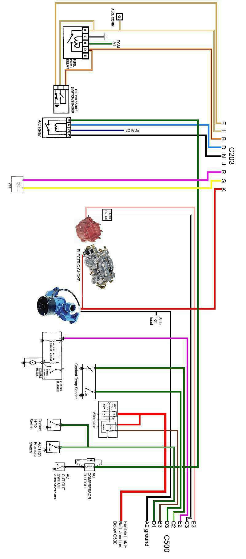
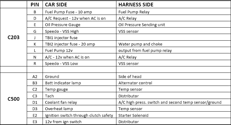
Chart on what wire is going where:


Now the questions:
Pin A on the Fuel Pump Relay was connected to pin A1 on the ECM. Can I assume that this is the signal to tun on the fuel pump and needs to be connected to a 12v ignition wire? Is it safe to assume that C203 Pin J (TBI1 injector fuse) would be a good spot for that?

Pin C on the A/C Relay was connected to pin C2 on the ECM. I am not clear what this is for...but since there is no ground connected to the relay, I assume that the ECM grounded it to allow the A/C to work? PLEASE correct me if I am wrong on this. Note that in stock form, the ECM receives a signal from pin A on the relay (B8 on the ECM)....I assume this is the signal that tells the ECM to ground it.

Thanx in advance for any thoughts on this...
IP: Logged
PFF
System Bot
fieroguru
Member
Posts: 12128
From: Champaign, IL
Registered: Aug 2003


Feedback score:    (45)
Leave feedback


Total ratings: 258
Rate this member

Report this Post03-01-2011 06:47 AM Click Here to See the Profile for fieroguruSend a Private Message to fieroguruDirect Link to This Post
 
quote
Originally posted by CowsPatoot:

Now the questions:
Pin A on the Fuel Pump Relay was connected to pin A1 on the ECM. Can I assume that this is the signal to tun on the fuel pump and needs to be connected to a 12v ignition wire? Is it safe to assume that C203 Pin J (TBI1 injector fuse) would be a good spot for that?

Pin C on the A/C Relay was connected to pin C2 on the ECM. I am not clear what this is for...but since there is no ground connected to the relay, I assume that the ECM grounded it to allow the A/C to work? PLEASE correct me if I am wrong on this. Note that in stock form, the ECM receives a signal from pin A on the relay (B8 on the ECM)....I assume this is the signal that tells the ECM to ground it.

Thanx in advance for any thoughts on this...


Pin A is used for the ECM to prime and run the fuel pump. The Oil Pressure switch also provides power to the fuel pump when oil pressure is present, so on a carbed application where you do not need the primer circuit, you can leave Pin A disconnected.

Pin C is the ground for the relay and the ECM controlled it so it could turn off the AC at WOT. Without the ecm in the picture, just connect it to ground and when you want to wail on the car, just turn the AC off.

IP: Logged
FFIEROFRED
Member
Posts: 750
From: GULFPORT, MS
Registered: May 2008


Feedback score: N/A
Leave feedback

Rate this member

Report this Post03-01-2011 07:36 AM Click Here to See the Profile for FFIEROFREDSend a Private Message to FFIEROFREDDirect Link to This Post
A 1972 Vega fuel pump is a elec in tank fuel pump for a carb. IT is a little shorter so you will need a little longer peice of hose.
IP: Logged
Arns85GT
Member
Posts: 11159
From: London, Ontario, Canada
Registered: Jul 2003


Feedback score: (1)
Leave feedback


Total ratings: 202
Rate this member

Report this Post03-01-2011 12:23 PM Click Here to See the Profile for Arns85GTSend a Private Message to Arns85GTDirect Link to This Post
I carb'd my 2.8. Same job.

You take your ignition power off the pink wire in the center console tunnel. You take the black ground.

For the electric choke, you use the white wire from the passenger side block that normally feeds the injectors.

I used the stock v6 pump with a bypass regulator. Lots of gas and the pump just idles along.

I really like your ability to draw up a circuit. That is really kind of professional and all, but, it is a litlte easier my way.

Arn
IP: Logged


All times are ET (US)

T H I S   I S   A N   A R C H I V E D   T O P I C
  

Contact Us | Back To Main Page

Advertizing on PFF | Fiero Parts Vendors
PFF Merchandise | Fiero Gallery | Ogre's Cave
Real-Time Chat | Fiero Related Auctions on eBay


Copyright (c) 1999, C. Pennock