I got a couple decent gen2 motors from a firebird at the junkyard and am rebuilding them with new grease and bushings. However...will they bolt up to the Fiero linkages? Or did I need the Firebird linkages? They looked different so I didn't take them... I currently have the gen1 system...86 GT. Thanks!
The motors from the early 90's firebirds will bolt right in. You use all the linkage from the fiero. It goes right on the motor shaft. You do swap the motors. FB right motor goes on the left Fiero. Did you get the headlight module from the FB? Sometime the motors don't like to work with mixed motors.
Are you putting them in a gen2 headlight Fiero? (87-88)
IP: Logged
02:08 PM
masospaghetti Member
Posts: 2477 From: Charlotte, NC USA Registered: Dec 2009
I saw the wiring diagram and it looks fairly simple to modify the existing harness to incorporate the new motors. I did get the module from the Firebird along with the motors.
I've removed the headlight buckets and motors a few times before to service the gen1 motors...do you think the conversion is feasible within a day's work? BTW, the reason i'm swapping over is because the limit switch on one of my gen1 motors is becoming erratic and I think its draining my battery.
Easily doable in 1/2 a day. I converted my '84 based 308 kit a couple years ago and it was simple. If you don't have ready access to the wire diagram for either car I can post them both for you.
IP: Logged
03:55 PM
masospaghetti Member
Posts: 2477 From: Charlotte, NC USA Registered: Dec 2009
See my cave... Gen 2 HL motors in lighting section. Upgrade is link on page
------------------ Dr. Ian Malcolm: Yeah, but your scientists were so preoccupied with whether or not they could, they didn't stop to think if they should. (Jurassic Park)
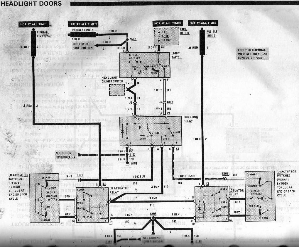
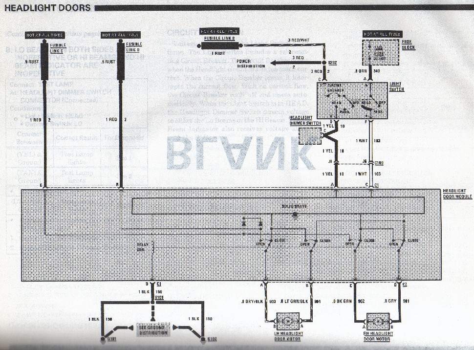
As promised, I've posted the two different generation wiring diagrams below, but understand that they're from Fiero service manuals so the wire colors won't all be the same on the connectors you have if you harvested the Gen2 components from the Firebird, but the modules are exactly the same with the same pinouts. I happen to have a copy of the Firebird schematic here as well but decided not to include it to avoid any unnecessary confusion, but in the step by step instructions below, I refer to the colors that you should find on your Firebird harness to help identify some of the circuits.
Here's what you have to do:
1. Disconnect the battery because you'll be playing with Hot At All Times circuits;
2. Unplug the isolation relay and snip off the connectors;
3. Determine where you want to mount the new module;
4. Splice the white wire from the iso relay to an extension running to module connector C1 pin C (dark green wire on Firebird harness)
5. Splice the yellow wire from the iso relay to an extension running to module connector C1 pin A (yel wire on Firebird harness)
6. Splice the black wire from the iso relay to an extension running to module connector C1 pin D (black wire on Firebird harness)
7. Remove the Gen1 motors, unplug the motor relays and cut off the connectors including the two single pin connectors with the blue wires;
8. Lead an extension wire from each of the two red wires near the motors to the module. LH red wire goes to module connector C1 Pin E (red wire on Firebird harness) and RH red wire goes to module connector pin B (red wire on Firebird harness)
9. On the Firebird RH motor, the wires should be dark blue and light blue. This now becomes your LH headlight motor. The Firebird LH motor should have a dark green and a light green wire. This now becomes your RH motor; If the motor wires are grey and green on both motors, then install the motors and skip to step 13;
10. Install the Gen2 motors where they belong;
11. For the new LH motor (with dark blue and light blue wires):
a. splice the dark blue motor wire to the dark blue wire from the old Gen1 system near the motor, then go to the other end of the dark blue wire near the old iso relay and splice an extension onto it leading to module connector C2 pin B (drk grn on Firebird connector);
b. splice the light blue motor wire to the pink wire from the old Gen1 system that leads up to the old iso relay location. To find out which of the two pink wires it is, you'll need to do a continuity check. Then go to the other end of the pink wire near the old iso relay and splice an extension onto it leading to module connector C2 pin A (lt green on Firebird connector);
12. For the new Fiero RH motor (with dark green and light green wires):
a. splice the dark green motor wire to the dark blue/wht wire from the old Gen1 system near the motor, then go to the other end of the dark blue/wht wire near the old iso relay and splice an extension onto it leading to module connector C2 pin C (drk blue on Firebird connector);
b. splice the light green motor wire to a new wire that leads up to the new module connector C2 pin D (lt blue on Firebird connector). Skip to step 15;
13. For the new LH motor (with green and grey wires):
a. splice the green motor wire to the dark blue wire from the old Gen1 system near the motor, then go to the other end of the dark blue wire near the old iso relay and splice an extension onto it leading to module connector C2 pin B (drk green on Firebird connector);
b. splice the grey motor wire to the pink wire from the old Gen1 system that leads up to the old iso relay location. To find out which of the two pink wires it is, you'll need to do a continuity check. Then go to the other end of the pink wire near the old iso relay and splice an extension onto it leading to module connector C2 pin A (lt green on Firebird connector);
14. For the new RH motor (with green and grey wires):
a. splice the green motor wire to the dark blue/wht wire from the old Gen1 system near the motor, then go to the other end of the dark blue/wht wire near the old iso relay and splice an extension onto it leading to module connector C2 pin C (drk blue on Firebird connector);
b. splice the grey motor wire to a new wire that leads up to the new module connector C2 pin D (lt blue on Firebird connector);
15. Tie up any loose wires left over from the gen 1 system near the motors, and reconnect the battery.
These instructions are based on the Fiero wire colors from an '86 service manual so there may be a few differences. If there are, and you get confused, just post what color wires you have and I'll try to figure it out for you. Good luck!
(Edited to fix mix up between C1 and C2 throughout text)
[This message has been edited by Bloozberry (edited 01-21-2011).]
IP: Logged
07:17 PM
Isolde Member
Posts: 2504 From: North Logan, Utah, USA Registered: May 2008
What the hell are you talking about? Pop-up headlights didn't appear until '82, which is third gen. '67-'69 was first gen, '70-'81 was second gen, '82-'92 was third gen, '93-'02 was fourth gen.
IP: Logged
09:55 PM
masospaghetti Member
Posts: 2477 From: Charlotte, NC USA Registered: Dec 2009
What the hell are you talking about? Pop-up headlights didn't appear until '82, which is third gen. '67-'69 was first gen, '70-'81 was second gen, '82-'92 was third gen, '93-'02 was fourth gen.
I meant FIERO Gen 2 motors, which is the same as the Gen 3 Firebird motors...sorry for the confusion. thanks for the information, Blooz!
IP: Logged
10:41 PM
PFF
System Bot
masospaghetti Member
Posts: 2477 From: Charlotte, NC USA Registered: Dec 2009
Looking at those diagrams makes me almost want to keep the Gen 1 system, just because its so clever! LOL. Really cool design...if only the limit switches were made more robust.
IP: Logged
10:44 PM
3084me Member
Posts: 1035 From: Bucks County, PA Registered: Apr 2005
What the hell are you talking about? Pop-up headlights didn't appear until '82, which is third gen. '67-'69 was first gen, '70-'81 was second gen, '82-'92 was third gen, '93-'02 was fourth gen.
Damn, I just got a set of Ultra Rare 6th Gen Firebird Headlight Motors from a seller on Ebay for $550. Did I get ripped off??
They came along with my electric supercharger and will add 80HP . .
:-)
[This message has been edited by 3084me (edited 01-20-2011).]
IP: Logged
11:57 PM
Jan 21st, 2011
Isolde Member
Posts: 2504 From: North Logan, Utah, USA Registered: May 2008
I honestly had no idea about this, it seems you're saying '88 Fieros used different headlight motors than '84 Fieros? Thanks for clarifying.
Yeah, 84-86 were gen1 motors (same as 82-86 Firebirds, IIRC) and 87-88 were gen2 (same as 87-92 firebirds). The gen1 system used a series of relays and a mechanical torque switch to stop the motors when they reached the end of travel. The gen 2 system uses a control module that senses current draw, and can tell when the motors have hit their stops. You can see the difference in Blooz's wiring diagrams. The problem is that the gen 1 system, being heavily mechanical, wears out and becomes unreliable with age.
The other problem is that no one appears to be making the isolation relay anymore for the Gen1 headight system, and they're starting to fail regularly now. You can cobble up something equivalent to the iso relay with a bunch of parts, but it's not as clean. The Gen2 headlight system is cleaner since you replace three relays with one module and get rid of several wires. Though the module costs close to $200 after taxes if it ever dies.
Anyone know if it is possible to make a gen 1 motor into a gen 2 motor. I am thinking that if I modify the brush/limit switch assembly into two simple brushes in each motor, I could connect them to a controller module and it 'should' work the same as the gen 2 motors would.
You would have to by-pass one switch and use it's lead and the common on the motor and abandon the unused lead. However the modules are designed to work a motor of a certain current draw. If the Gen1 motor draws current to different from the module design parameters it will not function correctly.. You would have to test it and see if it would work. Guess the good thing is it could be tested without damaging the motor so it would be converted back to gen1 again. All modules are not the same. Even in all the GM systems from Firebirds, vets, etc. you mix modules and motors and they sometimes will not work.
[This message has been edited by Dodgerunner (edited 01-21-2011).]
IP: Logged
11:20 AM
masospaghetti Member
Posts: 2477 From: Charlotte, NC USA Registered: Dec 2009
Anyone know if it is possible to make a gen 1 motor into a gen 2 motor. I am thinking that if I modify the brush/limit switch assembly into two simple brushes in each motor, I could connect them to a controller module and it 'should' work the same as the gen 2 motors would.
Please keep us updated on this, I am very curious about this as well.
IP: Logged
12:22 PM
PFF
System Bot
3084me Member
Posts: 1035 From: Bucks County, PA Registered: Apr 2005
Why be like that when someone is wanting facts set straight? Not helpful.
Isolde, lighten up. I think you're reading my comment the wrong way. I'm making a joke at MY expense.
Ummmm . . . that's a joke . . . No disrespect was intended . There is obviously no 6th Gen F-body car and several others had already chimed in to make the O.P aware that pop-up headlights were on 3rd gen and Later F-bodies. (Ps. I agree Bloozberry, who cares - we all know what the O.P was referring to in the first place).
No need for 150 people to post that 3rd gen F-body cars had pop ups and your "Ultra-Helpful" comment: "what the hell are you talking about" etc.
Your "what the hell comment" wasn't helpful ---> FAR MORE than my joke was.
I think the posts above "set the fact straight" that pop up headlights are on 3rd /4th gen cars. The O.P isn't even asking about what Gen car's the motors came on...
I thought I'd lighten it up a bit at MY expense saying I got ripped off.
Ps. to the O.P and others that commented, This is a great post. I wasn't aware of the differences in the headlights or that the F-body parts could be used. Good to know. Sorry for taking it O.T. for a post there.
[This message has been edited by 3084me (edited 01-21-2011).]
IP: Logged
12:41 PM
masospaghetti Member
Posts: 2477 From: Charlotte, NC USA Registered: Dec 2009
4. Splice the white wire from the iso relay to an extension running to module connector C2 pin C (dark green wire on Firebird harness)
5. Splice the yellow wire from the iso relay to an extension running to module connector C2 pin A (yel wire on Firebird harness)
6. Splice the black wire from the iso relay to an extension running to module connector C2 pin D (black wire on Firebird harness)
Blooz, did you mean connector C1?
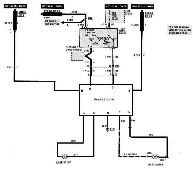
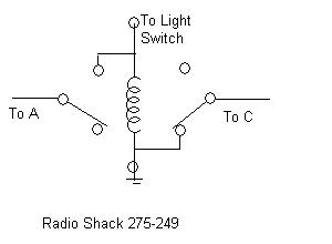
I am trying to bench test my motors and electronic module, I have it connected like Dodgerunner's diagram shows:
C1: Input to electronic module A - Yellow - B - Red - +12v C - Brown - D - Black - Ground E - Red - +12v
C2: Output to headlight motors A - Motor 1 B - Motor 1 C - Motor 2 D - Motor 2
When I connect +12v to the module, both motors spin for 5 seconds, then shut off. I understand this is a built-in safety feature to prevent the motors from running indefinitely. HOWEVER, I also understand that the module should reset once the headlight switch is cycled, and this doesn't seem to be happening.
It appears that +12v on C1, pin A should cause the motors to open the headlight doors, and +12v on C1, pin C should cause the motors to close the doors. Is this correct? When I apply +12v to either pin A or pin C, nothing happens.
Yes it sounds like your doing it correctly. The motor is stopping from the timeout. Normally the motor stops when the light hits the stop limit which then causes the module to turn off the motor. The motor should run either direction as you are doing it. It's possible that since the motor is not hitting a load limit the module is acting different. (is the module a known good one? ) If you remove all power and then try the other direction does it work? What your doing is how I test mine. I usually have both motors connected and in buckets when I do.
IP: Logged
01:49 PM
masospaghetti Member
Posts: 2477 From: Charlotte, NC USA Registered: Dec 2009
The module was taken from the salvage yard, so I don't know if it's good or not.
When you say "try the other direction", do you mean reversing polarity of the motors, or moving the +12v from Pin A to Pin C? The latter doesn't change anything, much to my dismay.
Unfortunately I dont have buckets to use as tests, because the car is 4 hours away now...
IP: Logged
01:55 PM
3084me Member
Posts: 1035 From: Bucks County, PA Registered: Apr 2005
I seem to remember that I may have a module laying round somewhere (I've had appx (8) 3rd gens, (1) 4th and still have my 79 T/A - love those F-Bodies..)
If I can track it down maybe I can "compare it for you, test it, or hell, I'll just send it to you, I don't need it.
I'm working on the replica today, I'll take a peek.
[This message has been edited by 3084me (edited 01-21-2011).]
Yes I meant moving from a to c. I have two sets of modules and motor out in the garage I could try it on later when I'm off work. One from an 87 fiero and the other from a FB.
Yes... I'm terribly sorry. I'll edit the text for future users. The reason this mix up happened is because I was working with the Firebird wire diagram in front of me when I wrote the instructions and it has C1 and C2 reversed as compared with the Fiero Gen2 diagram I posted. I just assumed GM would have labelled them the same but they did not.
IP: Logged
04:52 PM
masospaghetti Member
Posts: 2477 From: Charlotte, NC USA Registered: Dec 2009
Hey no problem, the only reason I brought it up was for those who might reference this in the future.
I really appreciate everyone's help on this...Dodgerunner it would be great if you could test your module at some point. and 3084me I will probably take you up on that offer if it turns out my module is really bad.
IP: Logged
05:24 PM
3084me Member
Posts: 1035 From: Bucks County, PA Registered: Apr 2005
. . .and 3084me I will probably take you up on that offer if it turns out my module is really bad.
Hey, No problem. I looked today and couldn't find it but I'm almost positive I've seen one around here. I did manage to find a few F-body seat belts, buttons, washer fluid bottle, fuel pump and various other 3rd gen things that are meaningless to you (and me since I only have one 2nd gen here).
I still have a few bins to go through. I'll keep you posted.
OK, I check my FB module set this morning. No buckets just the motors.
Applied power to B and E and ground D.
Apply power to A (up) and motors run one direction and time out.
Apply power to C nothing. Apply Ground to C motors run the other direction. Power never does anything on C. I'm now believe there is are two different wiring schemes for the FB modules.
Research time.
[This message has been edited by Dodgerunner (edited 01-22-2011).]
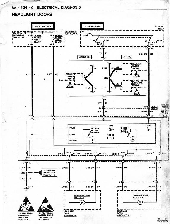
This is the schematic from the '94 Firebird service manual (IIRC), and although the labels on C1 and C2 are reversed (as I found out), it appears to have the same internal logic as the '88 Fiero, so perhaps there are different modules for different years as you suggest there DR.
Yes there are. The one you posted is basically the same as the Fiero module.
I have found another one that works this way. When you turn on the park lights power is applied to the C input. When you then turn on the headlights power is applied to input A. Light switch off A & C are open. the module seems to pulse the power out to the motors.
"Outputs randomly switch between drive and coast. Motors are powered in drive - Voltage from turning motor is sensed in coast. - Low coast voltage indicates actuator is at end of travel, stuck or disconnected. Output stays in coast when low coast voltage is sensed or after 6 seconds motor stops. "
So what that means is testing this type of module without the motors in a bucket to provide a stop the module will go into a shutdown mode hence they will probably not work correctly. The module I just tested is a 16509097 from a firebird. It works the same as the 16525685 discribed below.
I have compiled this information not 100% sure it's correct.
16523917 for 97-04 vet, 87-89 firebird, Fiero , 86-94 sunbird and 86-89 skyhawk. 16521291 86 Vet. reversing the signal wires for fiero 16525685 90-94 Sunbird, 90-02 Firebird, 90-92 Toronado and 90-92 Buick Reatta. That module will not interchange with the Fiero. 16507923 16507924 87-92 TransAm - Firebird. 16505400 87-88 firebird. 16521297 90-96 Vet. 16510537 88-96 Vet. 16509097 198? firebird 1989 Reatta
If using the 93-02 Firebird module (Part # 16525685) the wiring is a bit different. The up signal is wired exactly the same and can be done using the stock headlight switch. The down signal is accomplished by simply grounding terminal "C" on the Firebird control module. This will cause the lights to drop as soon as they are turned off, even if the parking lights remain on. So at this point there seem to be a couple different switching schemes. 1. The Fiero and some firebirds use lights up with power on A and down with power on C. 2. Some Firebirds and Vets use lights up with power on A and down with ground on C. 3. And a third does Power on C light switch in park, power to A headlight on (lights UP), Remove all power from A and C for Lights Down.
For # 2 you would need to add a Double pole double throw relay to switch power to A for up and ground to C for down.
[This message has been edited by Dodgerunner (edited 05-11-2011).]
IP: Logged
01:48 PM
Jan 23rd, 2011
masospaghetti Member
Posts: 2477 From: Charlotte, NC USA Registered: Dec 2009
OK, so looking at the diagrams, pins A and C might need +12v to cause the buckets to rise, or maybe just A -- depending on how the headlight switch is configured.
Either way though, my module seems unresponsive, with +12v applied to A, C, or both. The motors run for six seconds and shut off no matter what. I might have to rig up something to stop the motor travel. So it looks like I have module 16507923 or 16507924 (it was a later model firebird with a driver's airbag, so not 87-89).
So if you apply + to A they run for 6 sec and then stop. That sounds good. If you then apply ground to C do they run the other direction? If so then you have a working system but would have to add a relay as I show above to supply the ground for down.
If you can't get them to run the oppisite direction no matter what you do then you may have a bad module.
The two 097 modules I have both work this way with a ground on C no stops on the motors. So think they are both good just need a little different control setup.
[This message has been edited by Dodgerunner (edited 01-23-2011).]
IP: Logged
01:48 PM
Jan 27th, 2011
masospaghetti Member
Posts: 2477 From: Charlotte, NC USA Registered: Dec 2009
Update! I got a hold on a couple other modules and they test just like you say they should -- +12 on pin A makes the motors drive in one direction, +12v on pin C makes them go the other way. The first module must have been defective.
Thanks everyone for the help...I will be doing the installation here in about a week. Wish me luck!
Glad to hear the modules are working for you. I didn't know if they were any good or not, since they have been sitting in the totes for a while. Did you test both of them out?
Are these modules all the same part #? There are some FB modules that the vet guys use that operate with +12 to open and ground to close as I posted above. If they are all the same then maybe was a bad one, if not could just be the difference in the module.
IP: Logged
11:51 AM
Feb 4th, 2011
masospaghetti Member
Posts: 2477 From: Charlotte, NC USA Registered: Dec 2009
Just installed the gen 2 system and it works great, MUCH quieter than the gen 1 system (although I do kind of miss the meat grinding sensation)
Wiring was straightforward but kind of a pain and I ended up mounting the module just forward of the brake master cylinder, on the firewall. Thanks again everyone for the help.