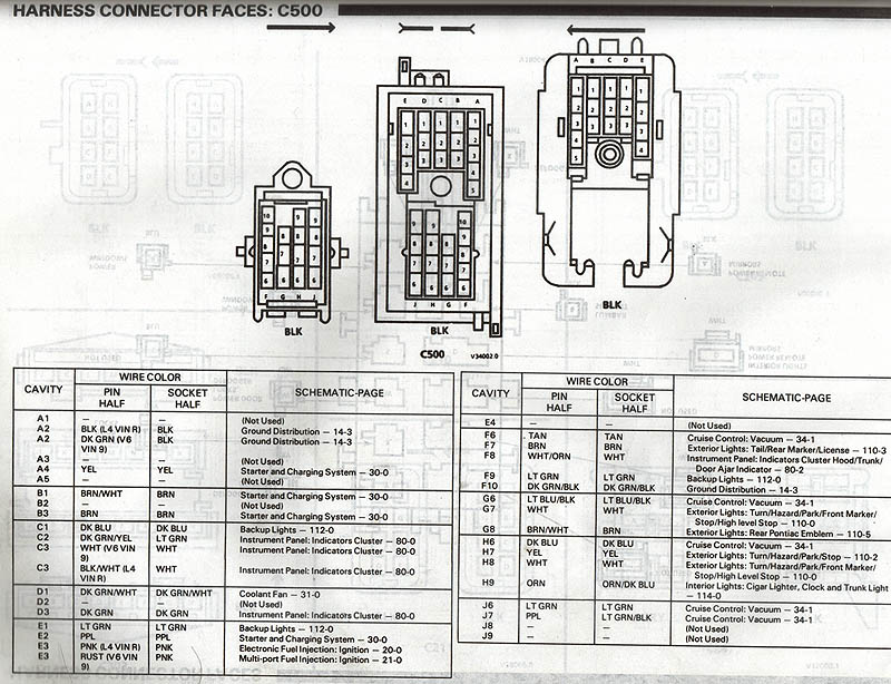
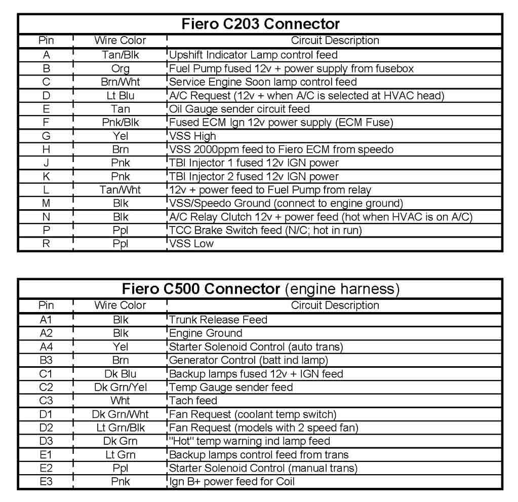
I am working on my 4.9 harness, and have discovered that the C203 and C500's are a little different for my 1988, as opposed to my 86 that I have pinouts locations for. Anybody have a scan of the 88 wiring that they can e-mail me? josef644 at hotmail dot com
Thanks Joe Crawford
[This message has been edited by josef644 (edited 07-23-2009).]
IP: Logged
10:47 PM
PFF
System Bot
jgrotzin Member
Posts: 349 From: Rocheport, MO Registered: Nov 2005
Busy right now, but I'll scan it and post it later this AM for you. Would have done it sooner but I assumed BMTFIERO sent you both diagrams in his PM. That's the problem with PMs... nobody gets to benefit from the info except one or two people.
IP: Logged
08:03 AM
josef644 Member
Posts: 6939 From: Dickinson, Texas USA Registered: Nov 2006
Busy right now, but I'll scan it and post it later this AM for you. Would have done it sooner but I assumed BMTFIERO sent you both diagrams in his PM. That's the problem with PMs... nobody gets to benefit from the info except one or two people.
That'ed be great. Thanks Joe
IP: Logged
09:58 AM
IFLYR22 Member
Posts: 1775 From: Tucson, AZ. Registered: May 2007
Here's a slightly different list than what Iflyr22 posted. It's from me having researched the 88 GM service manual drawings one by one. It's more detailed too because it lists the differences between the 4 cyl & 6 cyl engines, and auto & manual transmissions. The only pin out I could not find was for C203 pin A. Iflyr22's table shows that it should be for the upshift light, but based on the SM drawings, the upshift circuit is on pin P. With conflicting info, you'll have to double check wire colors to see which one applies to your car. Good Luck.
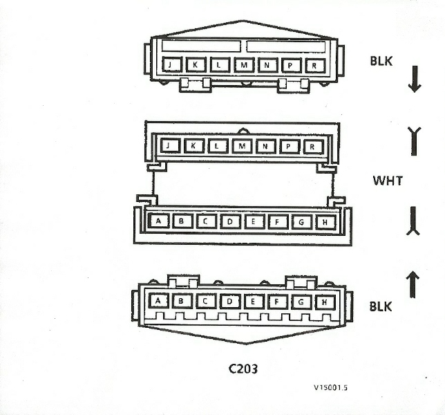
A = ?? B = orn/blk - F.Pump Fuse to fuel pump relay pin D and oil pressure switch pin C C = brn/wht - Instrument Panel Connector C3 pin 10 (SES light) to ECM pin C1 pin 22 (4 Cyl) or C2 pin A5 (6 cyl) D = lt blu - C100 pin A3 to A/C low pressure switch (4 cyl lt grn) (6 cyl lt blu) E = tan - Instrument panel connector C3 pin 17 (4 cyl) or Rally Gauge panel pin 3 (oil pressure gauge) to Oil pressure sender pin A F = for 4 cyl: pnk/blk - ECM IGN Fuse to fuel injector pin A and ECM C2 pin 16 (4 cyl) or ECM C2 pin A6 (6 cyl) G = yel - VSS pin B to Instrument Panel Connector C1 pin S H = brn - ECM C2 pin 23 (6 cyl) C2 pin 23 (4 Cyl) to Instrument Panel Connector C1 (dk grn/wht) pin U and Cruise Module pin D (dk grn/wht) J = for 6 cyl: pnk/blk - TBI INJ1 Fuse to Injectors (front bank)(pnk/wht) K = for 6 cyl: pnk/blk - TBI INJ2 Fuse to Electronic Vacuum Regulator Valve pin A (pnk) and Injectors (rear bank)(pnk) L = tan/wht - Fuel pump pin C to fuel pump relay pin B, oil pressure switch pin D and ALDL pin G M = blk/wht - Instrument Panel Connector C1 pin P to Ground G504 and ALDL pin A N = blk/wht - C100 pin A5 and Blower switch pin E to A/C compressor control relay pin D P = for automatic: ppl - brake switch to auto transaxle pin A (TCC) P = for manual: tan/blk - Instrument Panel Connector C3 pin 1 (Upshift light) to ECM pin C1 pin 7 (4 Cyl) or C2 pin A7 (6 cyl) R = ppl/wht - VSS pin A to Instrument Panel Connector C1 pin R
[This message has been edited by Bloozberry (edited 07-25-2009).]
IP: Logged
01:32 PM
josef644 Member
Posts: 6939 From: Dickinson, Texas USA Registered: Nov 2006
Sunday evening I pealed the wrappings off of the C203/C500/injector harness on the kitchen table while the wife as at a friends visiting. I followed the wires from the 203 or 500 and cut making the wires as long as would be possiable. Left the AC,ALDL, grounds and fuel pump stuff on there. Wasn't to bad. I am ready to start putting togeather the injector harness and the C203/C500 harness.
The baking at 250* for 15-18 min's worked great for removing the bulkhead connector. Ya forgot to tell us to wear gloves though. Joe Crawford
IP: Logged
12:30 PM
Sep 15th, 2009
josef644 Member
Posts: 6939 From: Dickinson, Texas USA Registered: Nov 2006
C500 'A1' a green wire, shows to be the trunk release on these charts. It should be black, but I have the trunk lead coming out of the C500 body part of the harness. I had cut the wire and tagged it when I removed the trunk lid. What the heck is this green A1 for? I did verify the position on C500
I've scoured the drawings in both my '86 and '88 manuals for any indication of C500 A1 being used for something, but came up empty handed. The closest I could come up with is the green wire in A2, which is just a ground wire running from G504 on the cylinder head, to splice S213, which is in the main harness behind the rear bulkhead grommet. Do you have a green wire in A2? If not, perhaps the factory mis-wired that one wire sticking it into A1.
Edit: On 1988 Fiero's only, C500 A1 is a dark green wire and is not the trunk release circuit nor a mis-wired connection to G504... see further below for more details.
[This message has been edited by Bloozberry (edited 12-29-2010).]
IP: Logged
07:13 PM
josef644 Member
Posts: 6939 From: Dickinson, Texas USA Registered: Nov 2006
I know this is an old post, but for the sake of putting everything in one spot for future searches (this comes up high on the list for C203 and C500)....
The C500 pin A1 is black wire with a white stripe. It goes into the wiring harness and follows it over to the fuel pump relay....from there, it exits and goes up to the left deck hinge where it controls the decklid release on an 85 Fiero. They changed the decklid wiring after 1985. This black wire gets a positive voltage when you press the deck release button. The decklid release then completes the circuit by grounding to the deck latch.
IP: Logged
01:17 AM
josef644 Member
Posts: 6939 From: Dickinson, Texas USA Registered: Nov 2006
I have those wires tied off and just hanging there unconnected. There were 4 wires that came out of the trunk lid. They all went in to the body portion of the C500. I have never checked them for any purpose yet. Joe
[This message has been edited by josef644 (edited 08-19-2010).]
Did any one figure out where the Dark Green wire from the C500 A1 on an 88 goes? The wiring diagram shows no wire in the in A1 location. I looked at the trunk open solenoid and trunk light/ajar switch wiring diagrams (for the 88) as mention earlier in the thread. None matches the green wire coming from the A1 connector position.
I have followed up the routing of the dark green wire from C500 pin A1 on my '88 GT, but only on the engine-half of the circuit. It leads to ALDL pin D. I haven't followed up on the chassis side, but I did search every drawing in the '88 service manual for a reference to ALDL pin D and found none. What I found interesting though, was that the proposed Electric Steering Assist had an electronic diagnostic terminal that may have been the intended purpose for this green wire. Since the diagnostic terminal was on the pump itself and would have been very difficult to get to, I speculate that leading an extension up to the ALDL would have been the logical thing to do. If this were the case, then I suspect that whenever somebody chases down the routing of the chassis side of the wire, they'll find it's been taped up.
IP: Logged
04:51 PM
ILVMYGT Member
Posts: 405 From: Port Orchard, Washington Registered: Jun 2003
I went back and look at the harnesses from the car. I found a cut green wire that went to the ALDL connector that matched the C500 green wire. That wire was bundled in with the ECM harness. I got my project after it had been started. All the wiring harnesses had been removed for the car and separated. Many of the connectors had been cut off. So it’s been interesting to sort it all out. So for the 3800 swap I am going either spare it out or cut it off a the C500 connector.