Well after a lengthy side track, I am back revisiting the driver side axle issue. Just to recap:
quote
Originally posted by fieroguru:
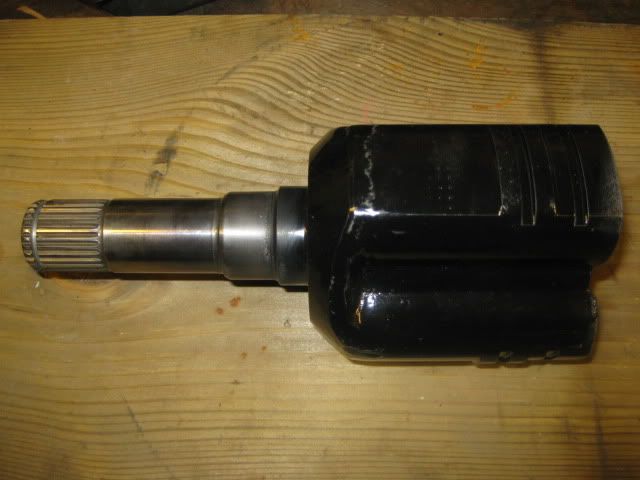
Over thanksgiving I visited Russ Fiero (BMW V12 swap guy) and had him make me one of these using the Saab 9-5 spline and a stock fiero tripod cup:
The cup was machined off the saab piece leaving just the splined shaft and a round flange where the tripod used to be. Then take the fiero tripod cup and cut off the spline shaft and machine a recessed area to accept the modified saab part. Then assemble and weld inside and out.
quote
Originally posted by fieroguru:
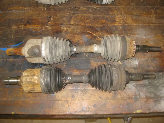
The 96 corsica axle came in today. It is indeed shorter than the fiero manual axle (top in picture) and has fiero compatible splines on both ends.
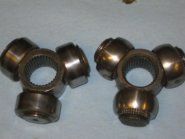
The tripod rollers are slightly different with the corsica ones being more flat:
The shaft spline is the same as the fiero manual, so I just swapped the roller ends and mocked it up with the hybrid tripod. The fully compressed length will just about align the upright to the lateral links, so it needs to be shorter to allow full range of motion without binding. Moving the snap ring and fine tuning engine/tranny placement might just get me there.
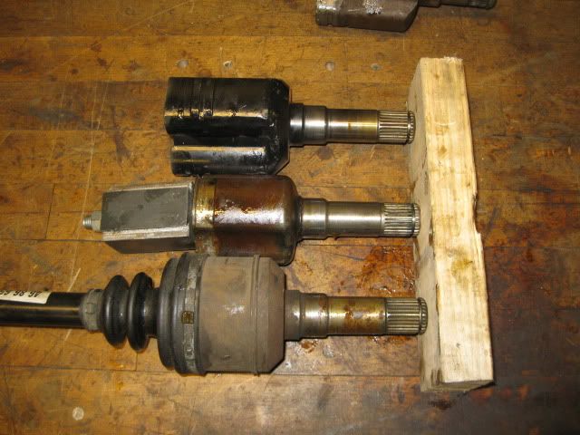
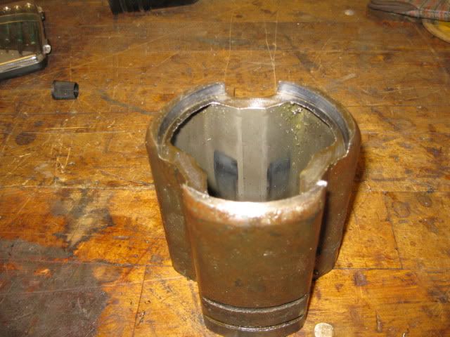
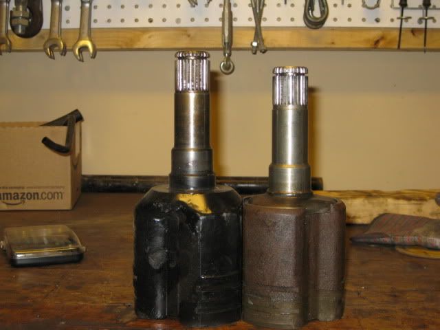
So the Saab/Fiero hybrid tripod & 96 corsica axle was still alittle too short... A while back I noticed that the shaft portion on the Saab tripod was longer than the one from the Torrent. I picked up an OEM torrent axle and it is slightly different than the EMPI version, but still the same length. Its shaft portion is about 1/2" shorter than the Saab unit, so using it to make a hybrid Torrent/96 Corsica tripod, I can gain about 1/2" axle clearance. For this hybrid, I am keeping the 96 Cavalier tripod housing so If I ever break the axle, I can just slide a stock 96 cavalier axle in place after removing the oem tripod housing. In this pic the Saab/Fiero hybrid is up top, the oem Torrent middle and the Saab 9-5 on the bottom.
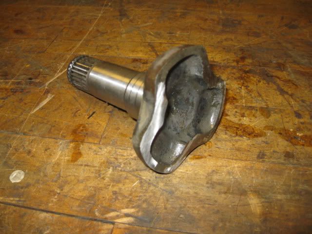
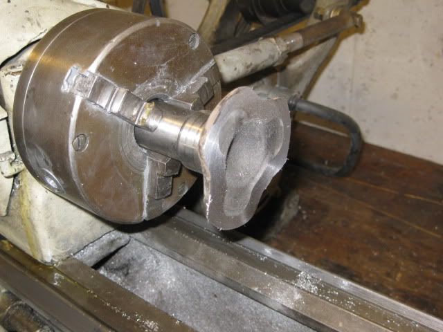
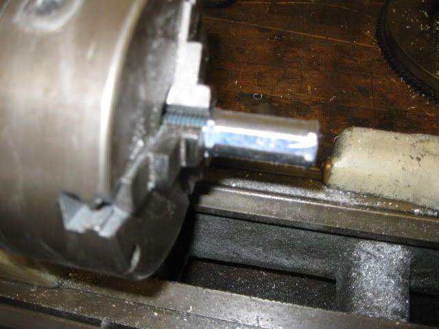
With the help of a 4 1/2" cut off wheel and a hand held grinder, I quickly rough cut the tripod housing off the shaft portion:
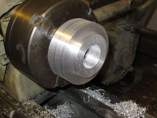
Then with a flapper disk on the grinder, I took off the excess material then chucked it in the lathe to finish the machine work.
So far this has taken about 1.5 hrs. On Sunday I will cut the shaft portion off the corsica tripod, then chuck it up in the lathe and machine the pocket for the Torrent shaft.
[This message has been edited by fieroguru (edited 03-06-2010).]
IP: Logged
06:22 PM
KurtAKX Member
Posts: 4008 From: West Bloomfield, MI Registered: Feb 2002
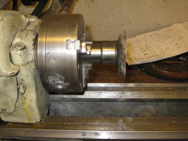
The hybrid 96 Corsica/Torrent tripod is coming along... The Corsica tripod housing is quite tough and next time I will use the cut off wheel and just cut the entire end off the tripod first and then put it in the lathe to clean up the end. But I did it the hard way and just cut off the shaft and then turned about 1/2" of material off the end... Took about 4hrs and was hard on the carbide.
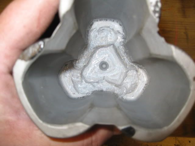
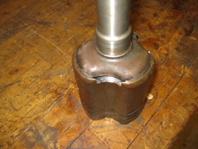
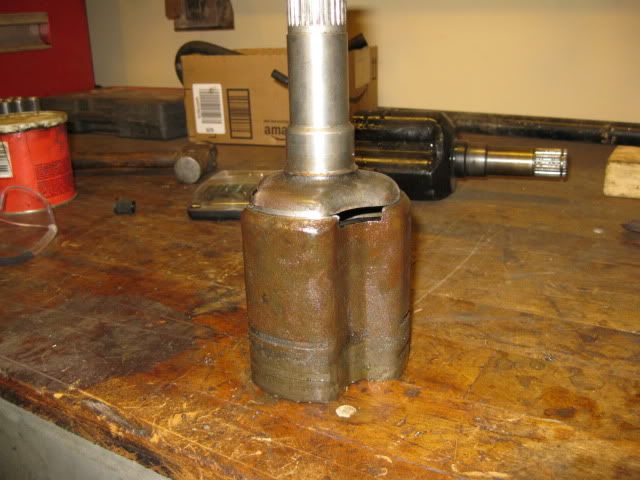
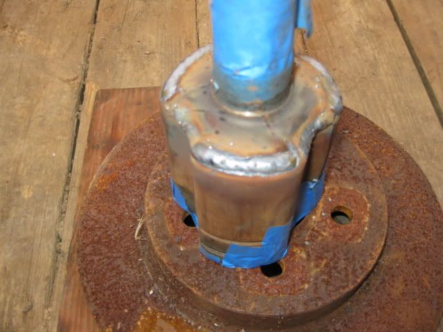
Test fit to check how much more material to remove off the shaft end:
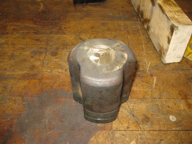
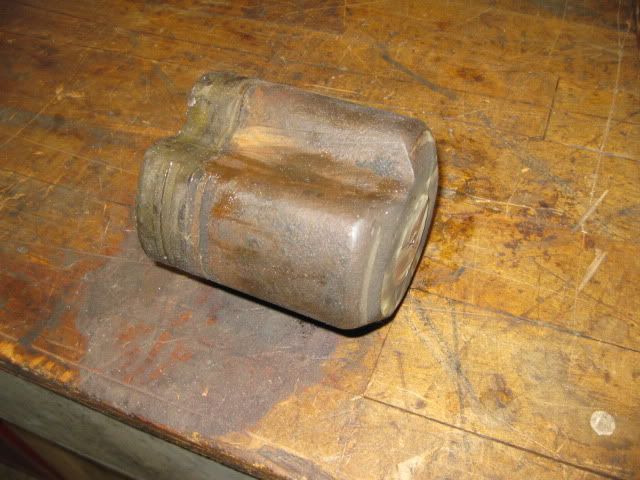
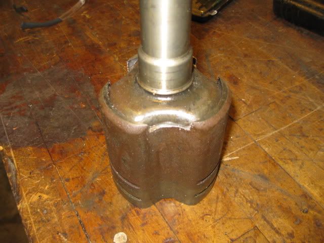
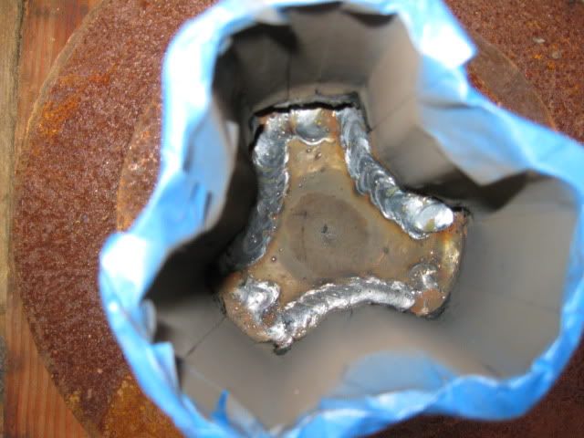
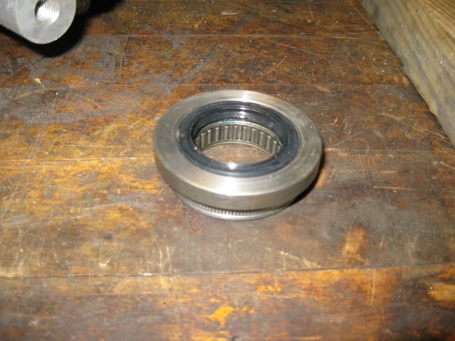
Just needs welding inside and out:
This is what I was after, a shorter hybrid tripod so the 96 corsica axle shaft will work on the driver side.
The longer fiero/Saab hybrid tripod works for the passenger side with the stock fiero manual axle shaft and helps makeup for the offset differential on the F40.
Once I have the corsica/torrent hybrid tripod welded together, I will move to the passenger side and work on a bearing support plate.
[This message has been edited by fieroguru (edited 03-07-2010).]
IP: Logged
08:39 PM
Mar 9th, 2010
fieroguru Member
Posts: 12127 From: Champaign, IL Registered: Aug 2003
Nothing fancy... just the stock lincoln gun that came with my Lincoln Pro Mig 175 and just the normal off the shelf welding wire from tractor supply...
IP: Logged
09:57 PM
cptsnoopy Member
Posts: 2585 From: phoenix, AZ, USA Registered: Jul 2003
guru, I'm convinced of your skills, but I'm still skeptical of the strength of your creation. I think it's good you left so much metal on the shaft, but I think you removed too much metal from the other part before welding them together. If your creation fails, it's gonna take out the trans with it. The upshot for me is you've convinced me of the value of just paying the DriveShaftShop 's asking price. Kudos on your ingenuity, and I hope it doesn't fail.
[This message has been edited by Isolde (edited 03-10-2010).]
IP: Logged
07:53 AM
fieroguru Member
Posts: 12127 From: Champaign, IL Registered: Aug 2003
guru, I'm convinced of your skills, but I'm still skeptical of the strength of your creation. I think it's good you left so much metal on the shaft, but I think you removed too much metal from the other part before welding them together. If your creation fails, it's gonna take out the trans with it. The upshot for me is you've convinced me of the value of just paying the DriveShaftShop 's asking price. Kudos on your ingenuity, and I hope it doesn't fail.
I am not worried about a failure... both of these hybrids are going to be used with the 4.3/F40 daily driver. If you remove less material from the tripod cage, then you will be limited to welding only on the outside. For increased strength of the joint, I wanted to be able to weld inside and out.
Long term, it would be great if an axle mfg (like EMPI) would make these hybrid tripods - they already make the Saab, Torrent, Corsica and Fiero tripods, it should just be a minor tweak to the machining programs.
[This message has been edited by fieroguru (edited 03-10-2010).]
IP: Logged
08:09 AM
fieroguru Member
Posts: 12127 From: Champaign, IL Registered: Aug 2003
The Fiero/Saab tripod with the corsica axle shaft w/ outer cv is 22 3/4" fully compressed and the Corsica/Torrent tripod with the corsica axle shaft w/ outer CV is 22 1/4" so the new hybrid axle gains me 1/2" on the driver side. I need to finish the adapter plate and test mock up the tranny/axles/suspension in the chassis and see if the 1/2" is enough or do I need to relocate the snap ring.
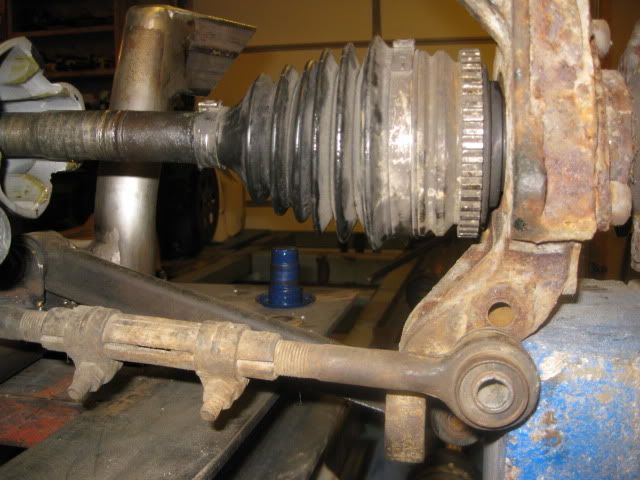
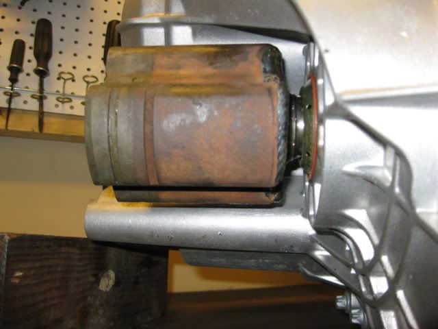
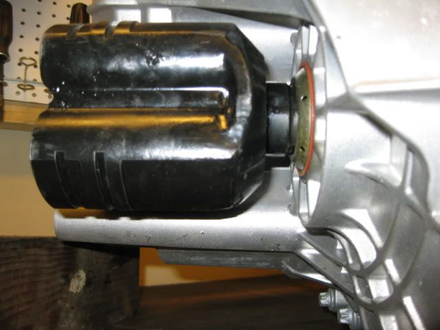
Here are some pics of tripods installed on the driver side. Corsica/Torrent:
Fiero/Saab:
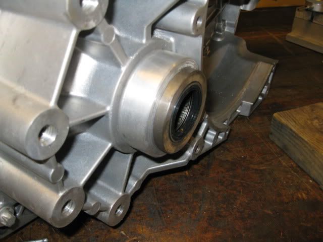
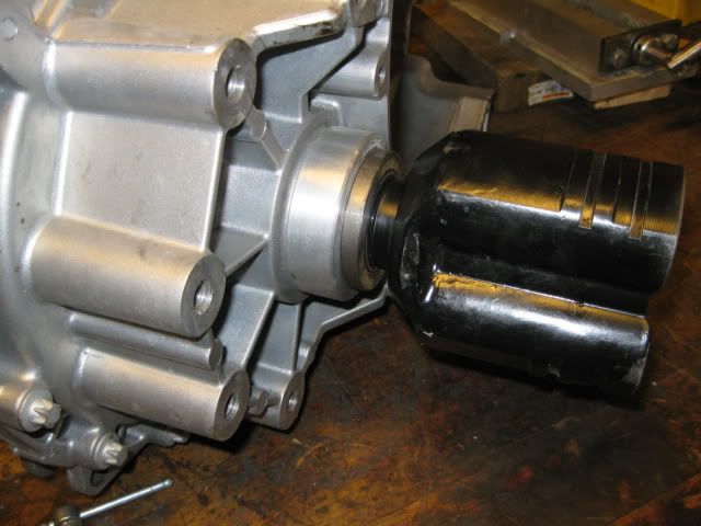
Now the other side with the Fiero/Saab:
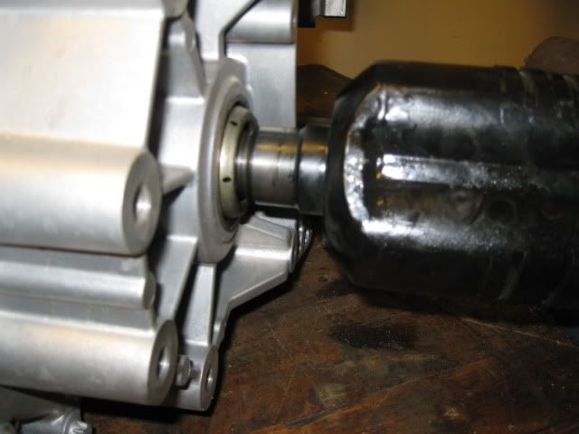
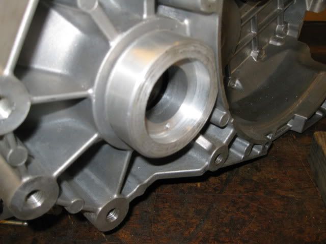
As you can see the tripod seal surface isn't close to the transmission seal, and the whole thing is sticking out unsupported further than I would like (remember this side was designed for the intermediate shaft with an external support).
The nice thing is the tripod seal surface and OD of the axle seal case on the F40 is an exact match for the stock fiero manual transmission seals and the corresponding axle stabilizer bearings. I am not a huge fan of the axle stabilizer bearings on the stock fiero transmissions, but I want something to help support the tripod further out from the case. I am hoping that with this being a 0 mile tranny and the increased distance between the bearing and the differential will help them work w/o issue.
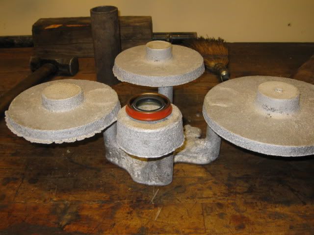
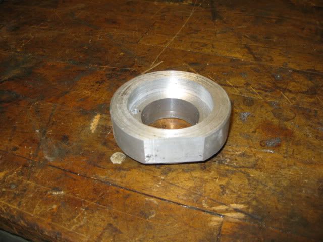
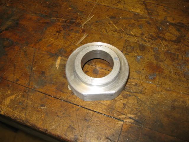
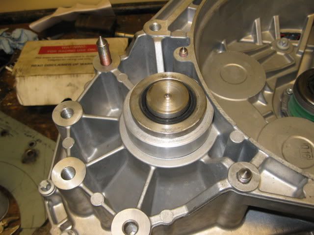
So the current plan is to make an aluminum housing that will press into the tranny seal location and be used to move the seal/stabilizer bearing about 1" to the passenger side. Then this housing would be bolted to the adapter plate from the engine side to help ensure it stays put and does not move. I went digging through all the cast aluminum goodies that came with the lathe (and all the melting/sand casting equipment) and found this collection of circular shapes. The one with the seal on it looks to be the right side to start with:
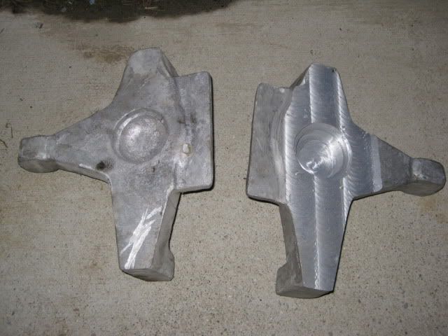
I also found these in the scrap aluminum: The guy I purchased all this stuff from was building a diablo tube chassis w/ custom suspension and corvette style uprights...
IP: Logged
07:29 PM
Isolde Member
Posts: 2504 From: North Logan, Utah, USA Registered: May 2008
I am not worried about a failure... both of these hybrids are going to be used with the 4.3/F40 daily driver. If you remove less material from the tripod cage, then you will be limited to welding only on the outside. For increased strength of the joint, I wanted to be able to weld inside and out.
Long term, it would be great if an axle mfg (like EMPI) would make these hybrid tripods - they already make the Saab, Torrent, Corsica and Fiero tripods, it should just be a minor tweak to the machining programs.
I admit I overlooked that you couldn't weld inside if you took less metal from that part. Now it looks to me like that's wgere most of the strength is since what's left on the shaft isn't thicker. With just a 4.3 and street radials, I'm not too worried for you. But I can't see making anything less strong than it could be. Thanks for sharing your nice machining and photos.
[This message has been edited by Isolde (edited 03-10-2010).]
IP: Logged
08:18 PM
PFF
System Bot
Isolde Member
Posts: 2504 From: North Logan, Utah, USA Registered: May 2008
It occurs to me, why wait for EMPI when DriveShaftShop obviously has found something? Or do you think DSS uses EMPI, or fabs their own? And if you figure $50/hr for your labor, you could've just sent DSS your measurements. On the other hand, you'd get no sense of accomplishment, and we wouldn't get to see what's involved and what's possible. So, has the work been stressful and draining, or has it been recreational?
IP: Logged
08:27 PM
fieroguru Member
Posts: 12127 From: Champaign, IL Registered: Aug 2003
Making the hybrid was a fun project and making more will be much faster based on what I have learned from this last one (Russ Fiero made my first one).
Sure with the time involved it is easy to justify spending $$$ vs. time, but I have more time than available $$$ for this project and there are other areas I would rather spend my available $$$. I am also planning to install the F40 in both of my current fieros and probably 1 more, so the cost for solutions to the flywheel, clutch, axles, shifter brackets, mounts, etc will eventually be multiplied by 3 (along with the seperate engine builds and other modifications). So, I am looking to keep the cost of every aspect to a minimum. If everything works out and I can reuse the stock fiero passenger axle, the 96 Corsica axle, the 2 hybrid tripods and the axle stabilizer, then my complete axle setup will cost about $200 in parts and 8-12 hrs of labor (but I have spent more than that on R&D so far, but still less than the DSS axles for a single car.
From the info I have seen on some of their applications, I think the driveshaft shop uses a common tripod design with female splines and makes stub shafts for the different applications, along with different axle lengths.
IP: Logged
09:52 PM
Mar 11th, 2010
Isolde Member
Posts: 2504 From: North Logan, Utah, USA Registered: May 2008
The axle stabilizer bearings are available from Fiero Store for 84.95 + shipping for two. I only need one right now and found a place I could buy them individually for 23.45 + shipping. I have one on its way and will know more once it shows up and I verify it is the right one and works.
IP: Logged
01:24 PM
fieroguru Member
Posts: 12127 From: Champaign, IL Registered: Aug 2003
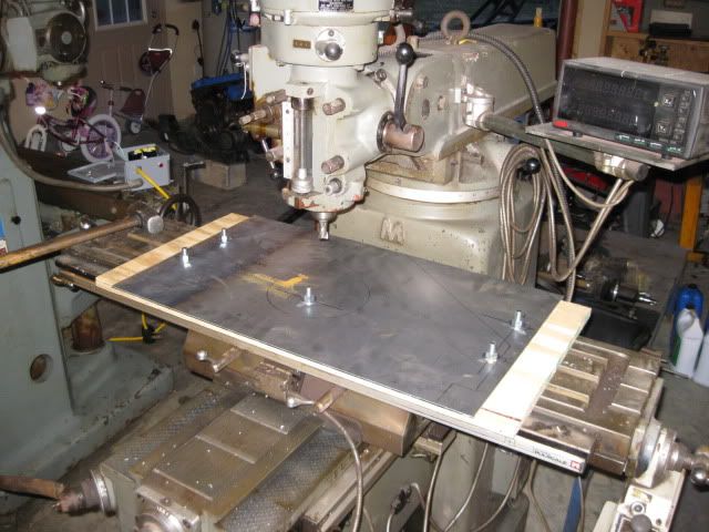
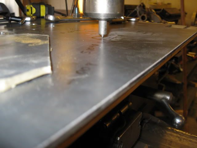
I am getting close to making my 1st adapter plate prototype off my autocad print. The first one is to check to make sure I have everything setup correctly and to refine some of the hole positions (the SBC bellhousing print only goes to 0.01").
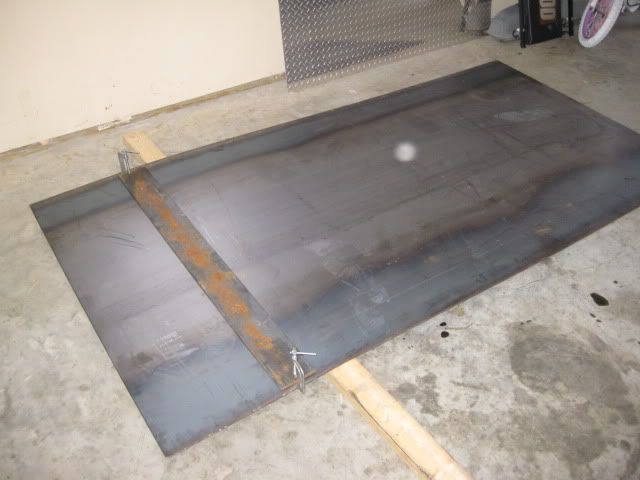
Cut the material from my 4x8 sheet and then drilled the 5 holes that line up with the T-slots in the table (but out of the final shape of the adapter plate) and get it mounted on the mill with a piece of plywood under it.
Sunday morning I will be doing some drill by numbers...
IP: Logged
07:06 PM
katatak Member
Posts: 7136 From: Omaha, NE USA Registered: Apr 2008
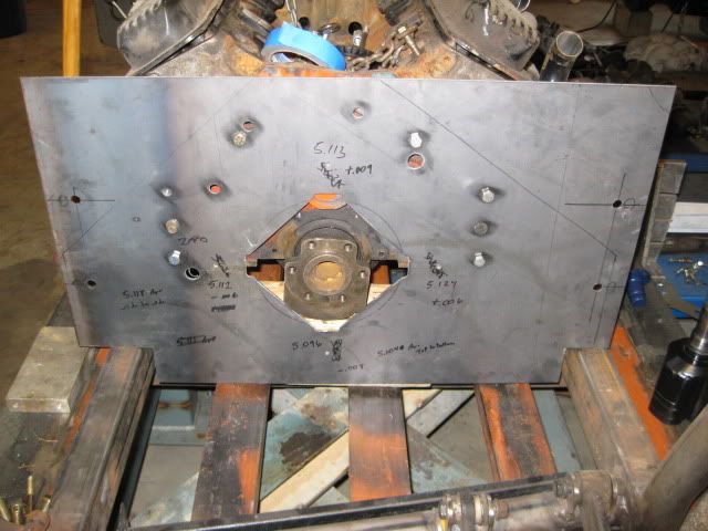
Got the adapter plate drilled via my autocad print and the crankshaft centerlines between the mock up engine and transmission are within .001" side to side and .003" top to bottom... I am pretty pleased with that. To drill the transmission dowel pin locations, I took a 3/4" drill bit and turned it undersize to the needed dimension for the first 1/4" in depth.
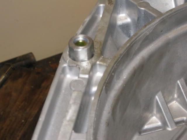
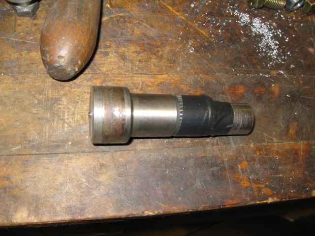
For the transmission dowel pins, I am using a 1/2" threaded rod coupler. This has a larger OD than needed for the dowel pin, so some lathe work got it to the proper size and left about 1/8" full side to be a flange on the engine side of the adapter plate (which will be welded to the adapter plate). This gives me a simple threaded boss for the dowel pin locations.
Here I am turning down the threaded coupler and the flanges are on both ends. I will cut it in the center to have the 2 needed dowel pins.
IP: Logged
03:32 PM
PFF
System Bot
Isolde Member
Posts: 2504 From: North Logan, Utah, USA Registered: May 2008
It's still missing the 4 needed holes to go onto an LS block.
It is missing several other holes (Tripod hole, mounting bolts around the differential and lower F40 bellhousing bolts). I do not own any LS based engines to properly locate those holes, but when I do aquire one, those holes can be added rather quickly.
I want to get all the missing holes located and added to my drawing for the next one.
IP: Logged
06:15 PM
Mar 15th, 2010
fieroguru Member
Posts: 12127 From: Champaign, IL Registered: Aug 2003
I got that plate from Speedway, the one you suggested, then I modified it until it would sit flush on the back of the LM7 and LQ4. Before I show the pics, let me type that I now plan to put some oil on the bolt heads, then put the plate in place, then use JB Weld. Once the JB dries, It'll stay stuck to the plate but not the oily bolt heads. Then I just need to sand one side of the plate flat, and I'll know exactly where the holes need to be on the next plate. Make sense? I can't sand both sides flat, or the JB might not stay put. But one side has to sit flat against the new plate. Anyway, here's the first pics to give you the idea.
IP: Logged
12:00 PM
Isolde Member
Posts: 2504 From: North Logan, Utah, USA Registered: May 2008
$289+ is NOT cheap. Not even worthwhile. You're better off buying a real LM7. At least that way you get a real block that can be bored, built and driven.
IP: Logged
01:09 PM
fieroguru Member
Posts: 12127 From: Champaign, IL Registered: Aug 2003
When the time comes, I will either get an LS4 or a LQ4... decisions, decisions, decisions...
For transferring the hole locations, I use normal bolts with the head ground down to a point via a drill press. Put a couple in the holes you want to locate, install the plate, then tap with a hammer... precise hole locations with minimal effort. With your plate the way it is, take the bolts out of the back cover and find some snug fitting washers and reinstall the bolts with washers over your current plate and tack weld the washers in place. Now you have the hole locations located. With that plate being thinner than the taper tip on the drill bit, use some 1/4" steel to shim the drill pattern plate from the material being drilled.
IP: Logged
01:33 PM
Isolde Member
Posts: 2504 From: North Logan, Utah, USA Registered: May 2008
When the time comes, I will either get an LS4 or a LQ4... decisions, decisions, decisions...
For transferring the hole locations, I use normal bolts with the head ground down to a point via a drill press. Put a couple in the holes you want to locate, install the plate, then tap with a hammer... precise hole locations with minimal effort. With your plate the way it is, take the bolts out of the back cover and find some snug fitting washers and reinstall the bolts with washers over your current plate and tack weld the washers in place. Now you have the hole locations located. With that plate being thinner than the taper tip on the drill bit, use some 1/4" steel to shim the drill pattern plate from the material being drilled.
I got the 1/4" shim covered, in the form of my original plate. The hack-job-looking one from my built thread. The tapered bolt idea is good, but got me the original holes needing elongated as pictured. As for spot welding washers, as welds cool, the metal shrinks, and that can pull the washer slightly off center. In that way, my method is even more precise. Me having 2 different blocks lets me be more sure I'm adequately compensating for any mass-production tolerance issues. The LS4 is a better plan than an LQ4. The LS4 comes with the #243 heads used on the LS2, and with different valves on the LS6. The LS4 can safely be bored to 5.7L, then just use the LS6 cam and computer, and you have a legal calibration for a manual trans LS. I was going this route, but with forged dished pistons for boost. Then it hit me that since I was set up for the non-LS4 versions of the LS blocks, I should do a N/A LS3 with Mast heads. More predictable, and a better balanced, lighter Fiero. The Mast heads are taller, but I already removed entirely my passenger side hinge box. The LQs need rod bolts if you want to go past 6500 rpm.
IP: Logged
02:11 PM
fieroguru Member
Posts: 12127 From: Champaign, IL Registered: Aug 2003
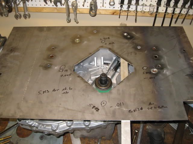
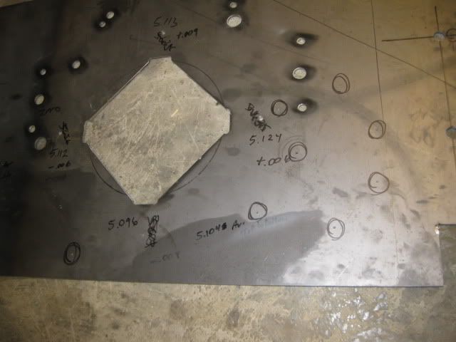
Here is a pic of some of the threaded hole locators I used to locate the last 8 holes in the tranny:
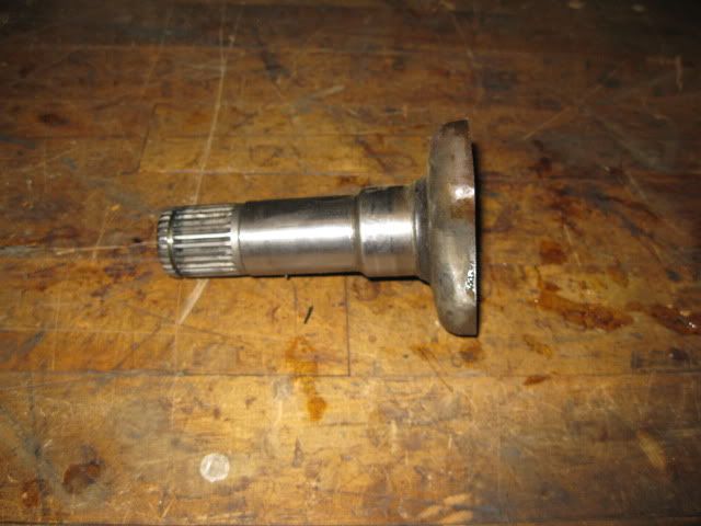
The one for the differential center was the old corsica shaft I cut off earlier, cleaned up the end to a point and taped a socket to the bottom of it so it would bottom out on the differential pin.
All the located holes are circled.
Now I need to spend some quite time with the calipers and my print to add all these bolt hole locations to the print.... might get that done on Tuesday evening... all depends on what other goodies come in the mail.
[This message has been edited by fieroguru (edited 03-15-2010).]
IP: Logged
06:45 PM
PFF
System Bot
Isolde Member
Posts: 2504 From: North Logan, Utah, USA Registered: May 2008
Wow man that is some great work..... Once you get it all sorted and get the final design done, care to share the dxf files? haha I just finished my cnc mill and I would love to be able to make a v8 adapter plate like that on it.... Keep up the good work.,.... peace
IP: Logged
10:30 PM
Mar 16th, 2010
fieroguru Member
Posts: 12127 From: Champaign, IL Registered: Aug 2003
Wow man that is some great work..... Once you get it all sorted and get the final design done, care to share the dxf files? haha I just finished my cnc mill and I would love to be able to make a v8 adapter plate like that on it.... Keep up the good work.,.... peace
I have no plans of sharing my final dimensioned drawing with all the bolt hole locations for my adapter plate... I learned a long time ago to never trust any print unless you have personally verified all the dimensions to be correct, and assume others would do the same. There is nothing overly special about it besides rotating the tranny relative to the engine to raise the axle centerline...
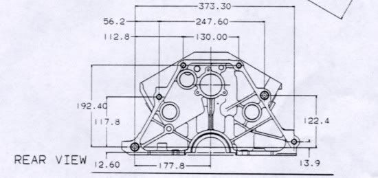
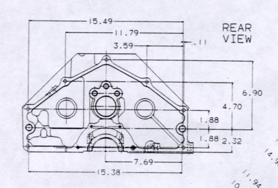
These two drawings are available on the web and are a decent starting point...
IP: Logged
07:12 AM
Isolde Member
Posts: 2504 From: North Logan, Utah, USA Registered: May 2008
Wow man that is some great work..... Once you get it all sorted and get the final design done, care to share the dxf files? haha I just finished my cnc mill and I would love to be able to make a v8 adapter plate like that on it.... Keep up the good work.,.... peace
What is "DXF"? Also, if Guru won't share his adapter plate results, I will be selling adapter plates of my own design, for attaching LSx engines to the F40. Mine aren't ready yet either.
IP: Logged
09:06 AM
fieroguru Member
Posts: 12127 From: Champaign, IL Registered: Aug 2003
It is a generic file type of drawing that is accepted across many different cad programs.
Damn technology, damn expensiveness. I shoulda been born 50 years sooner, when a man who was skilled with his hands was properly valued and appreciated. guru and I both would've been in high demand. Who decided to give our skills over to electronics? That was a bonehead move worthy of endless torture to everyone responsible.
[This message has been edited by Isolde (edited 03-16-2010).]
IP: Logged
12:05 PM
fieroguru Member
Posts: 12127 From: Champaign, IL Registered: Aug 2003
Damn technology, damn expensiveness. I shoulda been born 50 years sooner, when a man who was skilled with his hands was properly valued and appreciated. guru and I both would've been in high demand. Who decided to give our skills over to electronics? That was a bonehead move worthy of endless torture to everyone responsible.
The advances in CAD and 3D modeling are astounding and save a great deal of time in R&D for manufacturing companies. I learned AutoCAD on R12 about 14 years ago, did some work with ProE, and have a personal copy of R14 at home and AutoCAD2008 on my work laptop. However, unless you have tools/equipment that can use the precision in the CAD package, it can be wasted effort. You can also fall into the pitfall of unessessary precision...
IP: Logged
02:30 PM
Mar 18th, 2010
fieroguru Member
Posts: 12127 From: Champaign, IL Registered: Aug 2003
I took a piece of 3/8" rod and used the lathe to put a sharp point on it. After the plate was reinstalled on the mill and precisely located about the SBC dowel pin locations, I put the pointed rod into the mill and used it to locate the last 8 hole positions with the DRO.
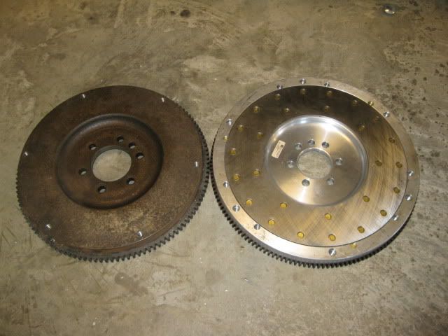
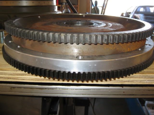
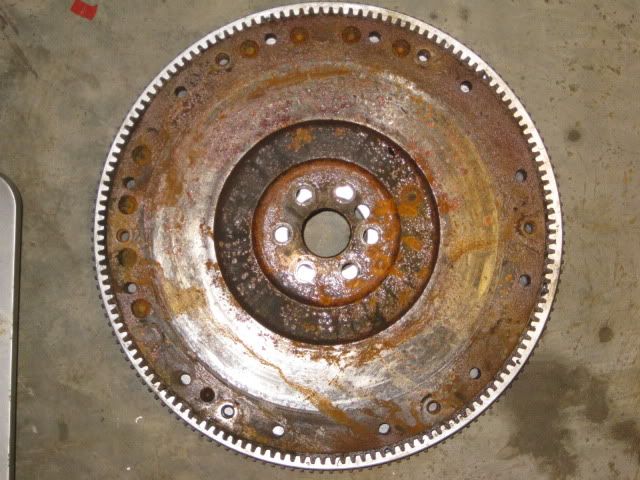
The flywheel I modified previously was for a pre 86 SBC and the first application for the F40 will be a 86+ SBC/4.3 so I needed to modify another flywheel. It is no fun turning down a cast iron flywheel and the steel billet one was much better. While surfing ebay I came across a new aluminum flywheel for the 86+ SBC with a 153 tooth ring gear for 225 shipped. It showed up today and tips the scales at 12 lbs (my modified billet one is 22 lbs) and I will remove additional material from it to install the fiero sized ring gear.
Here is my modified billet flywheel next to the aluminum one:
Here is a stock fiero flywheel on top of the 153 tooth aluminum one: