You'd be just as well off to go with a stroker crank to get the torque increase, then choose existing headers that fit.
quote
Originally posted by fieroguru: The Ground Rules: 1. I know there are easier, tried and true methods/options, but I want to make something truly unique with an original design.
"existing headers that fit" on a SBC in a fiero is a very limited number... I am familiar with more than most, and do not really care for any of them.
I normally do not choose the easy or proven path... that simply is not my style. I like finding new and creative solutions and the amount of additional effort needed will lessen the chance for it to be copied. This will keep my cars unique and interesting (notice I did not say, lightest, cheapest, fastest, quickest, loudest, cleanest, best in anything, etc... because I really do not care about that crap). My cars and swaps are about how I wanted them done and the methods/solutions I figured out along the way.
IP: Logged
07:19 PM
fieroguru Member
Posts: 12128 From: Champaign, IL Registered: Aug 2003
I have a couple of questions. How much TQ do you think your cradle will handle? Can you remove the valve cover with out dropping the engine? (I didn't cut my hinge box but I cant remove the valve cover)
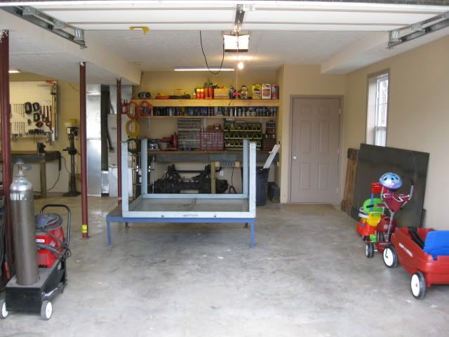
Thanks for posting, wish I had a place to work on cars like that.
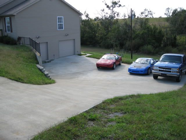
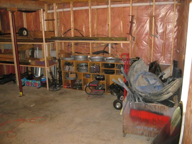
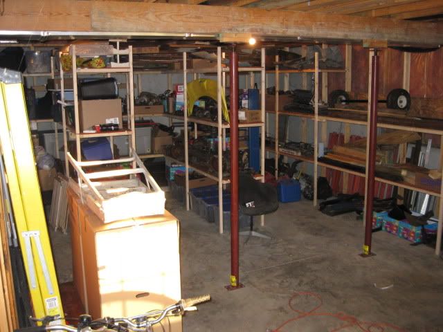
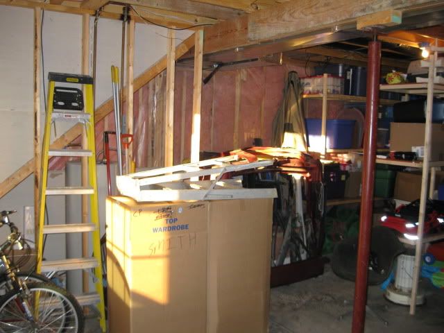
If I had my choice, I would rather not be moving... Since relocating to KY (and the housing market crash), I refuse to buy a house for at least a couple more years or until I sell my 3000sqft commercial building in IL... We have been in our current house for 3 years and it has a pretty decent garage - (taller ceilings and smoother concrete would be better). The house was the landlords retirement home and they are retiring at the end of this year. Our lease is up Sept 30th.... (I am not looking forward to the move at all). The new house has a garage about the same size, just deeper and narrower than the current one. It also has an unfinished basement on the other side so it will allow a bunch of fiero stuff to be out of the way. The garage is build into a hill, so I am hoping it will be somewhat cooler in the summer and warmer in the winter.
As for the torque capacity of the cradle... haven't calculated it... but suspect the spot welded seam on the fiero rear frame rail or the front cradle attachements to the chassis will fail before the cradle does. The crossmembers were spread apart as much as I could (while keeping exhaust space). There will be 4 mounts holding the engine/tranny to these crossmembers to help eliminate any single point loading. At all tube transitions, the connection points either have the tubes interlocking and/or the weld surface area is greater than the shear surface of the 2" round tube.
When the final install is in, yes the valve covers front/rear will be removable. JefrySuko gave me a good idea on a hinge mod that I will be doing.
IP: Logged
07:51 PM
Aug 28th, 2009
Isolde Member
Posts: 2504 From: North Logan, Utah, USA Registered: May 2008
"existing headers that fit" on a SBC in a fiero is a very limited number... I am familiar with more than most, and do not really care for any of them.
I normally do not choose the easy or proven path... that simply is not my style. I like finding new and creative solutions and the amount of additional effort needed will lessen the chance for it to be copied. This will keep my cars unique and interesting (notice I did not say, lightest, cheapest, fastest, quickest, loudest, cleanest, best in anything, etc... because I really do not care about that crap). My cars and swaps are about how I wanted them done and the methods/solutions I figured out along the way.
IP: Logged
04:05 PM
Isolde Member
Posts: 2504 From: North Logan, Utah, USA Registered: May 2008
Ops, sorry, but what I typed, about a stroker crank, was aimed at the poster who wanted to buy headers from you.
quote
Originally posted by fieroguru:
"existing headers that fit" on a SBC in a fiero is a very limited number... I am familiar with more than most, and do not really care for any of them.
I normally do not choose the easy or proven path... that simply is not my style. I like finding new and creative solutions and the amount of additional effort needed will lessen the chance for it to be copied. This will keep my cars unique and interesting (notice I did not say, lightest, cheapest, fastest, quickest, loudest, cleanest, best in anything, etc... because I really do not care about that crap). My cars and swaps are about how I wanted them done and the methods/solutions I figured out along the way.
IP: Logged
04:06 PM
Aug 29th, 2009
2feido Member
Posts: 295 From: chicagoland area Registered: Jun 2006
I hear you on this one. I heard all this stuff when i was building my 5.0l SBF Fiero.... You did//do have better ideas for finding the the center of the bolt holes then i did. I used the "engine plate" (basically a piece of sheet metal sandwiched between the engine and trans from the factory) to located the engine block hole for the adapter plate.
One area i did have question about was your method for centering the transmission on the plate. How precise is the throw out bearing retainer? Would imagine it has greater manufacturing tolerances then an input shaft would have. But i'm 2-1 with my methods of making my plates. i still dont know why i was throwing clutches on my last build.
Anyways it looks good...
quote
Originally posted by fieroguru:
"existing headers that fit" on a SBC in a fiero is a very limited number... I am familiar with more than most, and do not really care for any of them.
I normally do not choose the easy or proven path... that simply is not my style. I like finding new and creative solutions and the amount of additional effort needed will lessen the chance for it to be copied. This will keep my cars unique and interesting (notice I did not say, lightest, cheapest, fastest, quickest, loudest, cleanest, best in anything, etc... because I really do not care about that crap). My cars and swaps are about how I wanted them done and the methods/solutions I figured out along the way.
IP: Logged
11:23 AM
fieroguru Member
Posts: 12128 From: Champaign, IL Registered: Aug 2003
I hear you on this one. I heard all this stuff when i was building my 5.0l SBF Fiero.... You did//do have better ideas for finding the the center of the bolt holes then i did. I used the "engine plate" (basically a piece of sheet metal sandwiched between the engine and trans from the factory) to located the engine block hole for the adapter plate.
One area i did have question about was your method for centering the transmission on the plate. How precise is the throw out bearing retainer? Would imagine it has greater manufacturing tolerances then an input shaft would have. But i'm 2-1 with my methods of making my plates. i still dont know why i was throwing clutches on my last build.
Anyways it looks good...
The PVC tube was to get it close and locate the engine dowel pins. Then I used the engine crank/flywheel to scribe the circle on the plate and then located the plate to the tranny via indicating from the scribe to the input shaft centerline.
I now have the plate all drawn up on AutoCAD with precise locations for all holes and dowel pin locations. For the final I will take it into work and drill by numbers on the vertical mill and mill slots at 3, 6, 9 & 12 oclock positions that will be used to confirm proper tranny location to the engine.
IP: Logged
12:17 PM
Isolde Member
Posts: 2504 From: North Logan, Utah, USA Registered: May 2008
I'm not understanding it from your description. But my past successful adapter plates were done by getting on a lathe and making something that's a tight fit over the trans input shaft, and a tight fit to the rear of the crank, drilling the plate holes oversize, then letting the alignment determine where to fill in the plate holes with JB Weld. Let that all set up, take it apart, and your first plate just became your drill template for your final plate. Yes, it's twice the materials, but it's infalliable. for clarification, the plate bolts to the F40, then the oversize holes are for the bolts into the LM7. the LM7 is on it's nose, the trans above that. Then extra long bolts are oiled and installed, and you can then get the JB around each bolt. The oil keeps the JB from sticking to the bolts, but it will stick to the plate.
IP: Logged
06:17 PM
Aug 30th, 2009
fieroguru Member
Posts: 12128 From: Champaign, IL Registered: Aug 2003
I'm not understanding it from your description. But my past successful adapter plates were done by getting on a lathe and making something that's a tight fit over the trans input shaft, and a tight fit to the rear of the crank, drilling the plate holes oversize, then letting the alignment determine where to fill in the plate holes with JB Weld. Let that all set up, take it apart, and your first plate just became your drill template for your final plate. Yes, it's twice the materials, but it's infalliable. for clarification, the plate bolts to the F40, then the oversize holes are for the bolts into the LM7. the LM7 is on it's nose, the trans above that. Then extra long bolts are oiled and installed, and you can then get the JB around each bolt. The oil keeps the JB from sticking to the bolts, but it will stick to the plate.
That should work and is similar to how I made my prototype adapter plate, but at 1/8" thin it can not be used as a drill guide (atleast not with my drill bits). For the final plate I want a simple method so I can verify the alignment on assembly and have a chance to fit them before they kill a clutch, lower end or tranny.
Once I validate the dimensions on my drawing are accurate, then I will get some 1" steel plate, take it to work, drill it to the print on the digital bridgeport and use it going forward for my drill guide so I can make them at home.
IP: Logged
05:45 PM
fieroguru Member
Posts: 12128 From: Champaign, IL Registered: Aug 2003
Procrastinating on packing and spent a few hrs today finish welding up the cradle. Just need to weld on the suspension tabs and the 4 tube endcaps and the cradle will be ready for mounts.
It now weighs 39 lbs.
Also took the time to oil and scotchbrite the round tubes to help keep the surfase rust at bay during the fabrication process.
IP: Logged
05:49 PM
Sep 1st, 2009
fieroguru Member
Posts: 12128 From: Champaign, IL Registered: Aug 2003
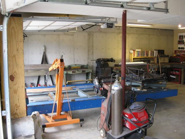
To avoid any futher distractions from "the move" I transported the tubular cradle, cradle fixture and SBC/F40 combo to the new house tonight (along with the 1st load of other garage stuff). So now I will not be able to work on it until the move is complete and the new shop is setup.
IP: Logged
09:36 PM
Sep 2nd, 2009
KurtAKX Member
Posts: 4008 From: West Bloomfield, MI Registered: Feb 2002
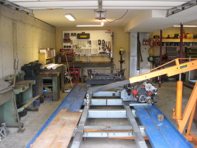
We are officially moved to the new place and spending our 2nd night here. I had everything garage related moved before last weekend and the garage mostly setup (still messing with the additional lighting and shelves/orgination of the storage room). Blackrams and family helped load up & unload the 26ft U-haul full of household items on Saturday and helped make that part of the move faily quick.
The next several days will be "honey do" and the final cleaning of the old place. I will know later this week if I will be heading back to IL on Thursday night to sign lease papers for my building up there. If so, then I will stop off at the local circle track shop and pickup some pre-fabbed brackets for the cradle lateral links (saves me from making them).
If all goes well I will be free to get back to this project early next week.
IP: Logged
08:00 PM
Oct 2nd, 2009
fieroguru Member
Posts: 12128 From: Champaign, IL Registered: Aug 2003
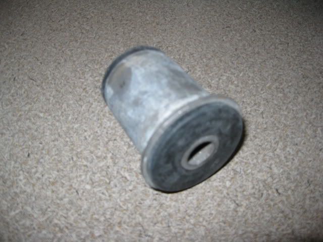
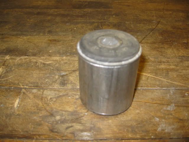
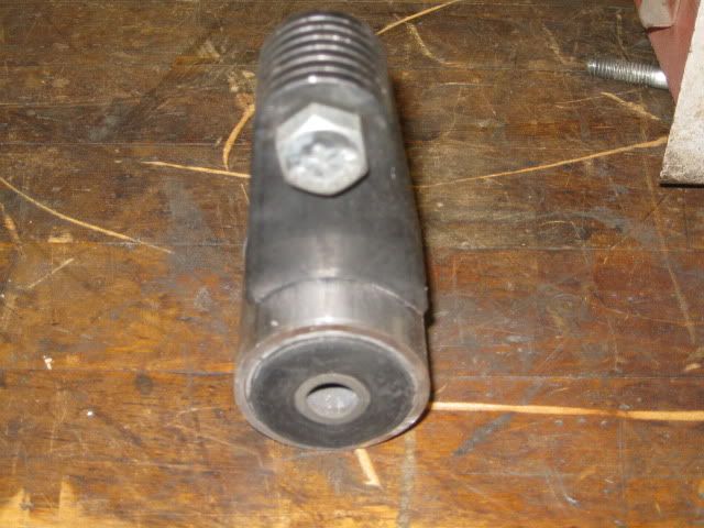
Did some R&D on the rubber mounts. I want to use a 4 corner mount system with round rubber bushings (similar to the 84-87 front cradle bushings Sinister Performance uses). These round suspension type bushings provide the positive location of the engine/tranny while allowing an amount of movement to minimize shock loading.
On my 4.3 swap I used poly bushings and the ends of the 88 trailing links for engine/tranny mounts. I can not find replacement rubber bushings for the 88 trailing links, so I need to figure out another solution.
I have plenty of the 2" tubing from the cradle left over, so I want to use it as the outer sleeve that will be welded to the engine/tranny brackets. Took my calipers to the local autozone where they know I am nuts and spent about 30 minutes in the bushing area opening and measuring all the bushings they had in stock. Found 3 that might be good contenders and then checked the price. The one with the $5.99 price became the winner.
This one is not a perfect fit to the 2"OD tubing, but I should be able to use either some shim tubing to make it fit tight, or just section the 2"OD tube to make it a smaller ID to fit the bushing. I really like the idea of getting all 4 rubber bushings for $24.
[This message has been edited by fieroguru (edited 10-05-2009).]
IP: Logged
07:17 PM
Oct 6th, 2009
fieroguru Member
Posts: 12128 From: Champaign, IL Registered: Aug 2003
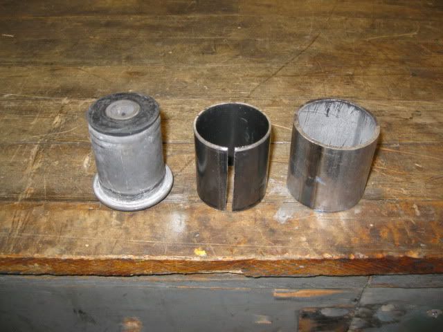
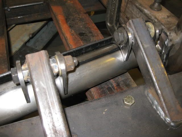
I think the $5.99 bushing will be perfect! A small length of 16ga 1 3/4" exhaust tubing is the needed shim for the bushing to fit snug inside the 2" cradle tubing. The 1 3/4" tubing needed to be slit to fit over the bushing and this opening provided additional clearance to the welded seam on the 2" tubing.
The shim slid over the bushing and then the bushing was pressed into the 2" OD tubing. To get it the last 1/4" in, I had to break out the mini sledge... so it is a fairly snug fit.
IP: Logged
05:39 PM
darkhorizon Member
Posts: 12279 From: Flint Michigan Registered: Jan 2006
Pricing the cradle bushings is what made me look further (call me cheap)... Autozone # FB235 $5.99
Uses a 1/2" center bolt. The 2" tube was 12ga (.108" thick).
I didn't want to wear out my welcome, or I would have priced checked more to see if there is something that could be had for under $5.
I would doubt you could beat that price of $6... its uncommon to get ANYTHING at an autozone that is behind the shelf for less than $5.... I mean heck most of the PCV valves are >$5.
IP: Logged
07:14 PM
Oct 9th, 2009
fieroguru Member
Posts: 12128 From: Champaign, IL Registered: Aug 2003
I finally got all the needed bushings. The local autozone had to get some in from a couple of other stores and wouldn't you know there were 2 that were boxed wrong... Eventually I got the 4 new ones I wanted (I am not going to try and take the prototype apart).
After work today I snuck downstairs for about 1 hr before dinner and cut all the tubing and sleeves needed for the engine/tranny mounts:
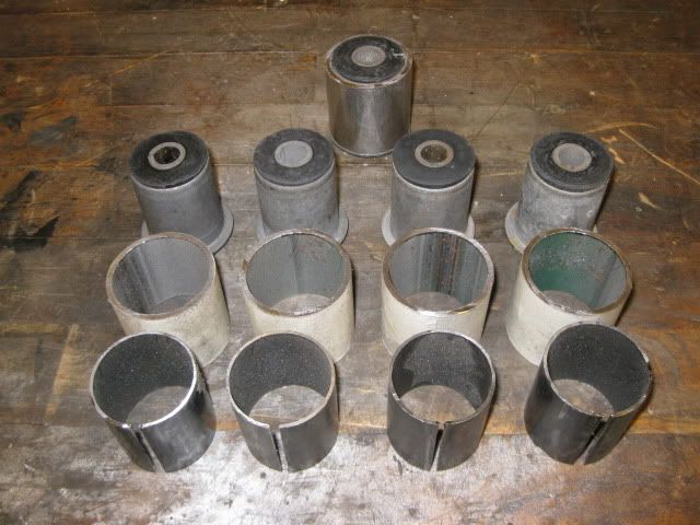
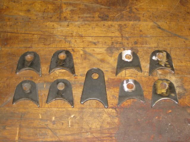
Here are the tabs for the suspension links - they came from speedway motors and cost $8.99 for a bag of 5 (I purchased 4 bags).
These are for 1 3/4" tubing, so I had to modify one to fit the 2" tube then put them all together and modify a set of 8 with my mockup one in the middle:
These have the upper hole around 1" too high. I will proably drill the lower hole for a stock suspension link location and then use these uppper holes if I want to raise the inner suspension points.
[This message has been edited by fieroguru (edited 10-09-2009).]
IP: Logged
06:09 PM
darkhorizon Member
Posts: 12279 From: Flint Michigan Registered: Jan 2006
Those links look nice, wish I would have thought of doing that for 1 or 2 of my mounts.
I ended up making mine "hotdog style" by just running plate longways across the bushing, and welding to it like that. Gave me a decent amount of surface area, and I could go on either side of it giving it tons of strength.
IP: Logged
08:33 PM
PFF
System Bot
fieroguru Member
Posts: 12128 From: Champaign, IL Registered: Aug 2003
Those links look nice, wish I would have thought of doing that for 1 or 2 of my mounts.
I ended up making mine "hotdog style" by just running plate longways across the bushing, and welding to it like that. Gave me a decent amount of surface area, and I could go on either side of it giving it tons of strength.
The links are for the lateral links for the rear suspension. I was just using the mock up bushing to show the fit to the 2" tube, I am not planning on using any of these purchased links for the engine/tranny mounts since those mounts will attach to the 2x3 rectangular tubes. I am planning of cutting those parts out of some other 3/16" plate I have on the shelf.
IP: Logged
10:10 PM
Oct 10th, 2009
fieroguru Member
Posts: 12128 From: Champaign, IL Registered: Aug 2003
I went ahead and just made the suspension links for the stock suspension locations. Drilled the new hole location and then trimmed down the excess height.
For comparison, here are 8 modified tabs for the lateral links and the original piece in the center:
Went to a lot of effort to make the top contours the same for all 8:
And the suspension tabs in place and ready to be welded:
IP: Logged
03:56 PM
fieroguru Member
Posts: 12128 From: Champaign, IL Registered: Aug 2003
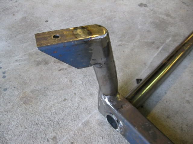
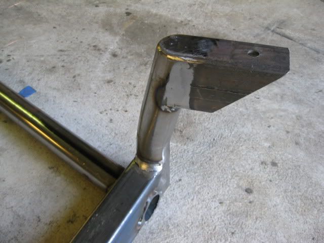
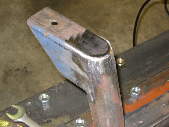
Something else I figured out... the tubing used in the trailing link on the 88 rear suspension is the right ID for the trailing link bolt where they attach to the cradle. So I cut the tubing the proper length and welded it to the cradle and added some gusseting... Pics once I get these finished.
IP: Logged
04:01 PM
drebinpk Member
Posts: 577 From: bridgeton mo Registered: Apr 2009
do you still have the getrag trans from the car is so would you be looking to sell it?
I am still driving my SBC fiero while all this work is going on. At some point I will be pulling the drivetrain and I am undecided what will happen to it - I might just sell the SBC/tranny/88 cradle as a plug & play swap...
The Getrag was rebuilt in 2007 and is the 92-94 version with the HTOB and the reluctor VSS - it might have 20K miles on it since the rebuilt.
IP: Logged
04:56 PM
drebinpk Member
Posts: 577 From: bridgeton mo Registered: Apr 2009
I went ahead and just made the suspension links for the stock suspension locations. Drilled the new hole location and then trimmed down the excess height.
Raising the inner pivot of the left toe link will run you right into the inner CV joint. You need to move the toe links forward to raise the pivots.
IP: Logged
10:20 AM
fieroguru Member
Posts: 12128 From: Champaign, IL Registered: Aug 2003
Raising the inner pivot of the left toe link will run you right into the inner CV joint. You need to move the toe links forward to raise the pivots.
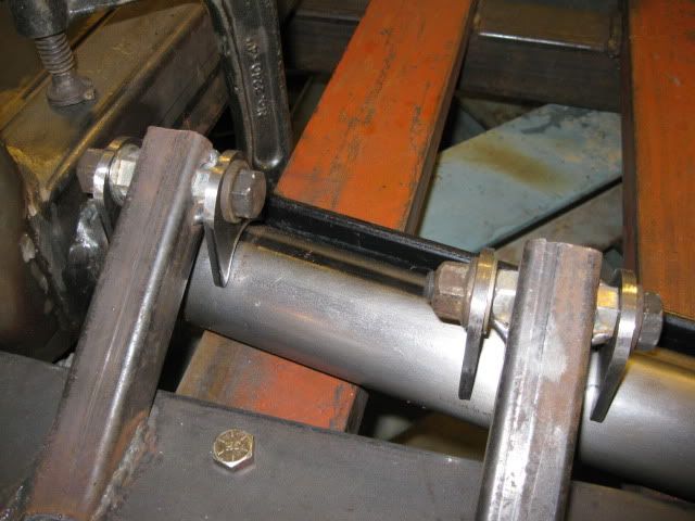
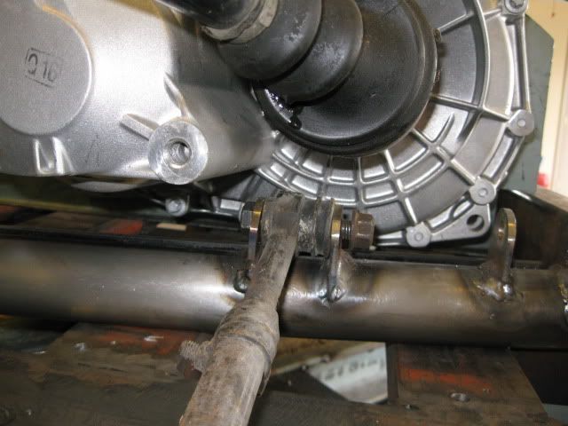
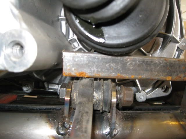
That would be true if I had a stock connection between engine/tranny and a factory 88 cradle. I have neither... so I do not need to move the link forward to raise it by 1". My tranny is rotated relative to the engine to raise the axle centerline coming out of the tranny about 1" and the suspension link tabs are shorter than the factory 88 suspension link boxes. The F40 also moves the driver side tripod out 1" (about 1 1/2" on my setup) so the boot retaining band (and its crimp fitting) is no longer above the suspension pivot..
My biggest clearance issue would be between the link bolt and the tranny bolt boss which I could clearance slightly.
1" square tube between the tripot and the suspension link:
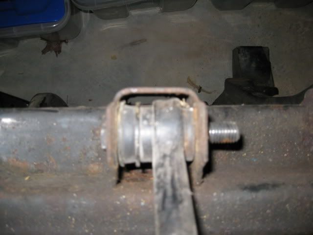
Stock 88 link attaching box:
My reason for leaving them the stock height was not due to clearance issues... mostly a time savings... The tabs are not symmetrical and the tube crossed under the suspension pivot point at an angle... so the forward tab is reversed from the rear one on each link. This greatly complicates hole locations to allow the tabs to be flipped and retain the proper alignment between 2 sets of holes... unless I wanted to drill them all individually...
The other factor was the tabs came predrilled with a 1/2" hole and a 15/32" hole provides a much tighter fit to the factory metric bolts and I like close tolerances. Most likely when I built one with the suspension pivots raised 1", I will not bother with drilling the lower set of holes and will convert to 1/2" bolts & rod ends for all pivot locations
[This message has been edited by fieroguru (edited 10-11-2009).]
IP: Logged
01:16 PM
PFF
System Bot
fieroguru Member
Posts: 12128 From: Champaign, IL Registered: Aug 2003
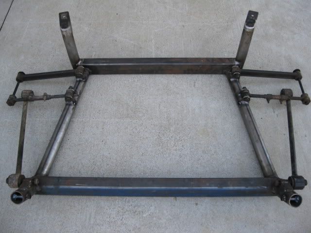
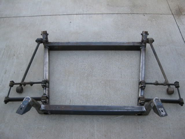
Just need to clean up some of the welds, but the cradle is just about done. Once I have the engine/tranny mounts completed, I may add a couple of gussets/corner braces.
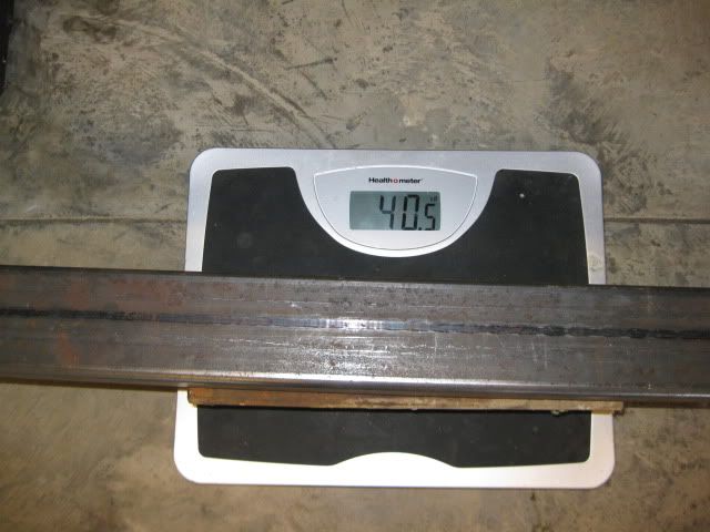
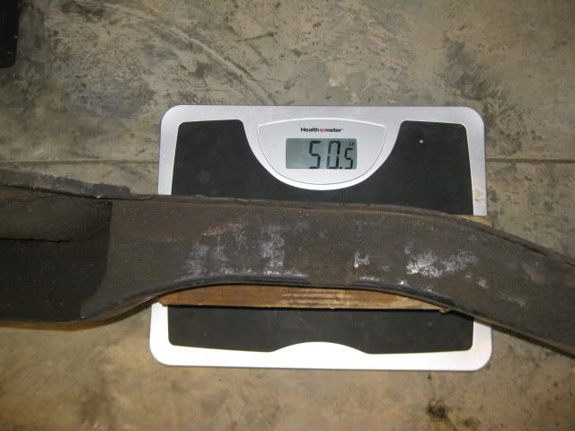
The bare cradle w/o any suspension links is 40.5 lbs and the stock 88 bare cradle is 50.5... so it is still 10 lbs less than stock (20% reduction).
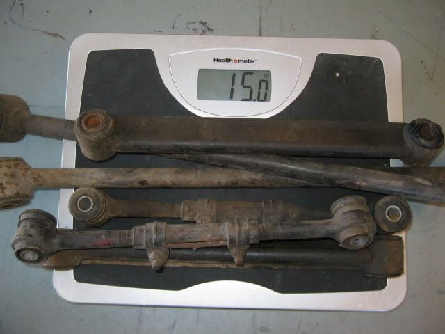
For grins, I weighed all the 88 rear suspension links - total w/o bolts is 15 lbs.
IP: Logged
03:17 PM
Oct 18th, 2009
fieroguru Member
Posts: 12128 From: Champaign, IL Registered: Aug 2003
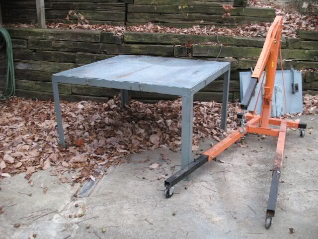
Yesterday I added some more crossmembers to this table so it would support the engine/tranny and become a tallish work table:
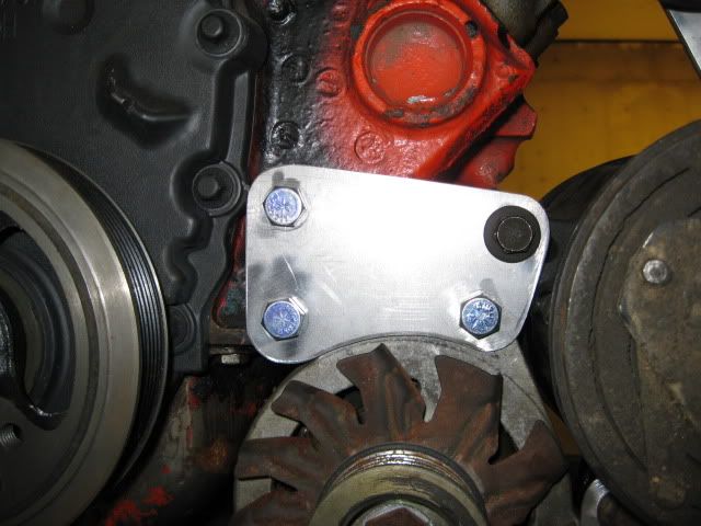
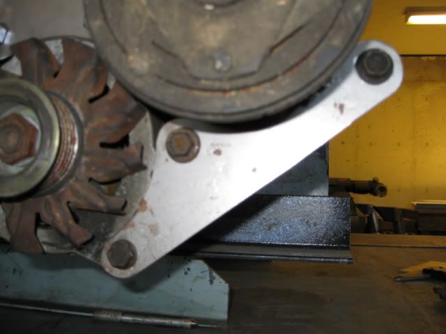
Today I took some 16ga sheet metal and made templates for the alternator/AC mount brackets.
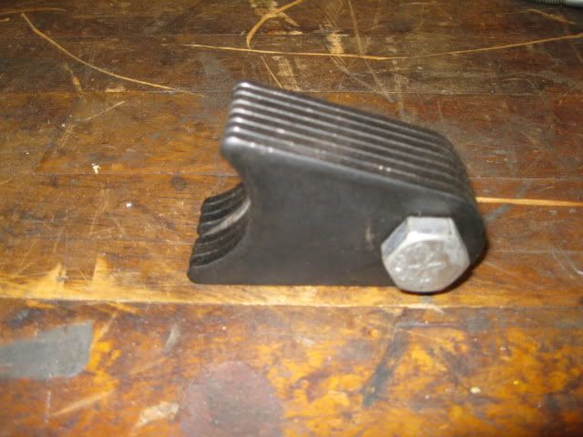
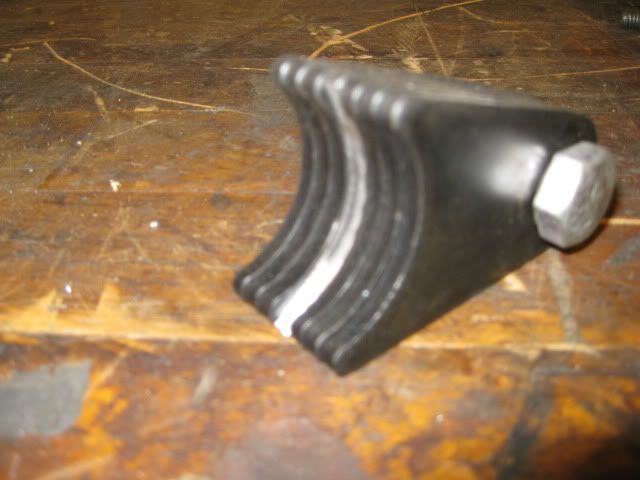
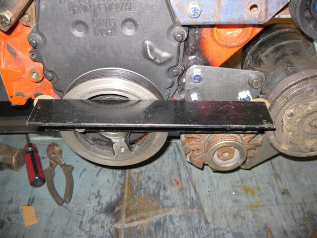
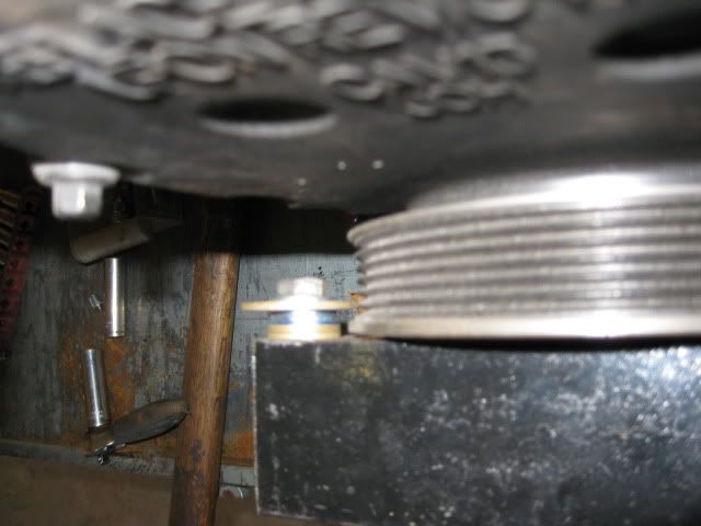
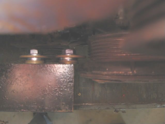
Here is the tool I made to check for proper pulley alignment. Just some angle bolted to the balancer and found the right combination of washers to locate the center of the 1st rib on the pulleys. Then I can use this assembly to ensure the pulleys are properly aligned.
IP: Logged
02:42 PM
Oct 19th, 2009
Isolde Member
Posts: 2504 From: North Logan, Utah, USA Registered: May 2008
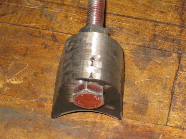
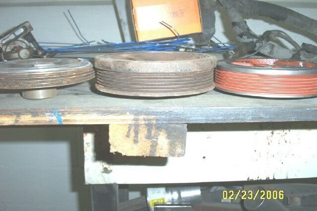
I think I'm starting to like that damper / pulley.
It is from a mid 90's 3.1 FWD application - cavaliers, corsica, barettas... they are all over the junk yark and can be picked up quite cheap. I figured out they fit the SBC in late 2005 and did some modifying of them in early 2006 before I relocated. The orange one was installed on my 4.3 swap last year. The one on the far left was an excersize in making it as thin as possible (4 rib vs. 6 rib). Its small OD makes it an underdrive pulley as well vs. the stock SBC pulleys.
[This message has been edited by fieroguru (edited 10-19-2009).]
IP: Logged
06:28 PM
Oct 20th, 2009
Isolde Member
Posts: 2504 From: North Logan, Utah, USA Registered: May 2008
Then you coulda had all 4 transverse links equal length, like the Corvettes.
I wanted to keep the factory 88 suspension geometry. I think you are referring to the C4 rear suspension setup, and its lateral links were much longer than they are in the fiero with their connections to the chassis about 12" to 18" inches apart (haven't owned a C4 since 2001).
IP: Logged
01:11 PM
Isolde Member
Posts: 2504 From: North Logan, Utah, USA Registered: May 2008