To be fair to the eternal mouse (sbc V8) the Competition-ported AFR180s are very competitive with most entry-level LSX heads. Alot closer than any other SBC head, including any of AFR's other offerings, which is a bit surprising. Yes, the 195s flow better at higher lifts, and the port volume seems closer, but that's not the whole story.
IP: Logged
03:21 PM
fieroguru Member
Posts: 12127 From: Champaign, IL Registered: Aug 2003
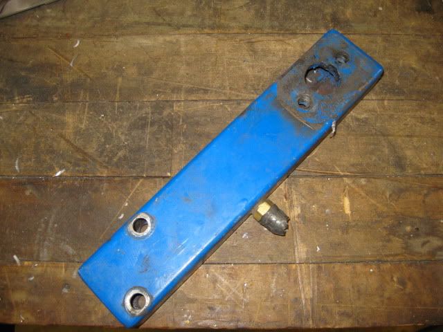
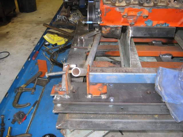
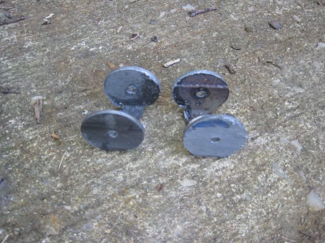
I was getting ready to put up the box of treasures that the prototype waterpump housings had been stored in when I noticed the actual rear housing I used until 2005 when the RamJet intake was added. This has the actual bolt pattern of the SBC setup so I can use this as a template to make the new ones.
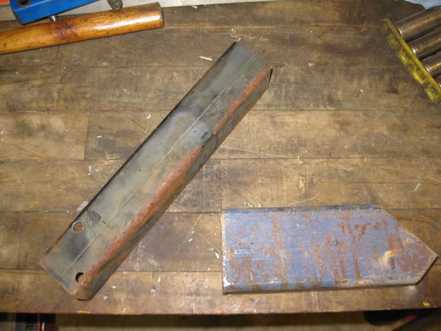
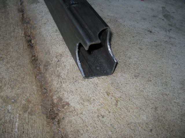
Since I moved the balancer in closer, the offset housings need to be 2" thick. I went through the scrap metal pile and came up with a length of 2x2 and 2x3 - both with 1/8" wall thickness. There will be modified for the new housings.
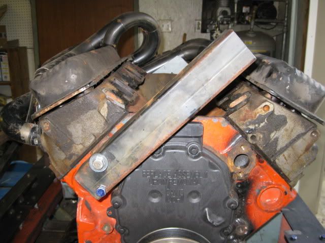
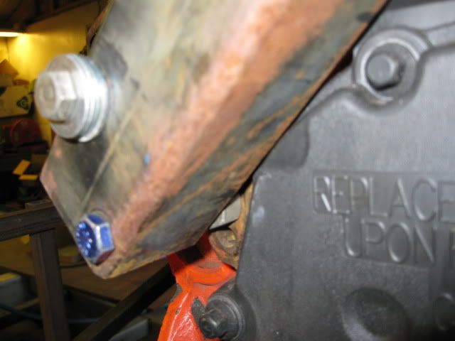
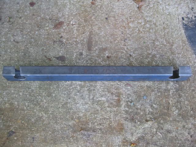
The angled one is nearly parallel with the cylinder deck and will need reliefs cut into it to clear the timing cover:
I am planning to shift the waterpump up about 1/2" on the new housings. This will allow the engine to be lowered and to gain additional clearance to the wheel well. On the current setup there is only about 1/8" clearance to the wheel well and that works just fine with solid mounts. Since I am going with poly, I want to plan for a little more movement.
This weekend I will see how far I can get on making these new ones.
IP: Logged
07:33 PM
Jul 25th, 2009
fieroguru Member
Posts: 12127 From: Champaign, IL Registered: Aug 2003
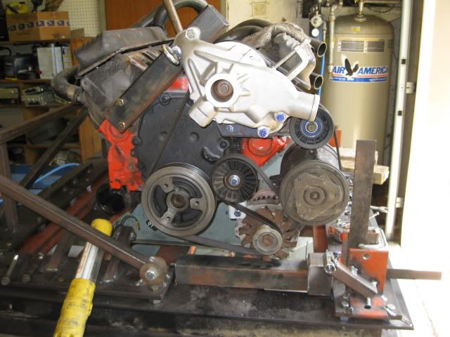
This is just a rough accessory mockup.... I will probably go through 15 or 20 iterations before I settle in on the best one.
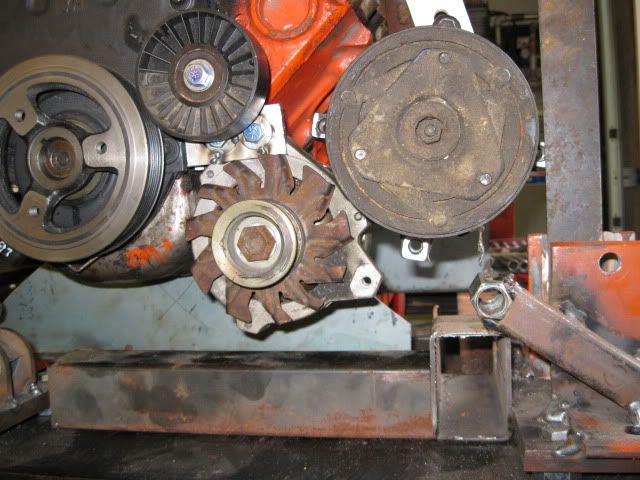
The SBC guys will notice I flipped the locations of the Alternator and AC compressor (just like I did on the 4.3). Couple of reasons for this, it allows the use of more traditional exhaust manifolds that come down before they start going to the rear of the engine. This allowed me to retain the stock manifolds on the 4.3 and will allow stock C4 corvette manifolds to clear the AC compressor (I will not finalize the mockup until I confirm they fit). These are factory stainless steel headers with factory heat shields and can be purchased used for under $100 most of the time. The other benefit is the alternator can be removed without doing anything to the AC compressor.
Here is why the tubular cradle is being done. Right below the alternator is a 2" square tube. This is where the new 2" cradle rail will go (and remember the base of this rail is 1/2" lower than stock. There just would not be room for the alternator with the stock cradle rails
IP: Logged
01:33 PM
fieroguru Member
Posts: 12127 From: Champaign, IL Registered: Aug 2003
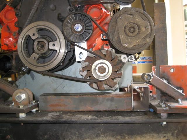
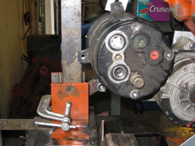
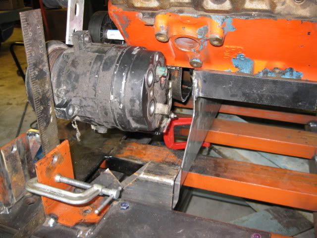
I went ahead and installed a 4.3 manifold with to make sure it would clear and moved the AC and alternator location a bit:
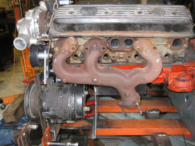
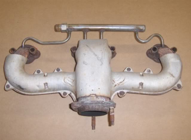
Here is the 84-91 L98 Corvette Stainless Steel Factory headers - They came on factory rated 240 hp 350's:
If you use the D-port heads, then the Corvette LT1 manifolds are a good option as well (cast iron with heat shields) and came on the 330 hp LT1 350's.
If anyone has a set of the C4 or the LT1 factory manifolds on the shelf they would like to loan me for mockup purposed, I would greatly appreciated it!
The alternator still clears the cradle rail and the square by the cradle bolt hole is 1" to the engine side of the front cradle mount. As long as nothing is past this point down low, it should clear the double firewall panel.
For the front engine mount, I am thinking about using the stock engine mount bosses and making a brace that will pick up the front crossmember. It will have to clear all the connectors on the back side of the AC compressor, but that should not be much of an issue.
[This message has been edited by fieroguru (edited 07-25-2009).]
IP: Logged
05:06 PM
Jul 27th, 2009
Isolde Member
Posts: 2504 From: North Logan, Utah, USA Registered: May 2008
Skip the GM junk and try a set of ceramic coated Hedman Tight Tubes. They're good for a solid 30 hp on a 400 hp 350.
I like GM junk... they do ALOT more R&D and durability testing on their parts than any aftermarket company. Peak hp has never been a main priority for me, but daily driver durability in rain or shine most certainly is. Either of these will last a lifetime, not have leaks at the heads or collectors and are cheap/easy to obtain. I am trying to compile the right combination of parts to make a L31/F40 swap cost effective for a daily driver.
IP: Logged
03:38 PM
Isolde Member
Posts: 2504 From: North Logan, Utah, USA Registered: May 2008
I pulled the SBC car into the garage, removed the rear wheels and wheel wells and started taking some general engine placement measurements.
Crankshaft centerline is 8 3/8" from the bottom of the 88 cradle. Crankshaft centerline is 15 1/8" from the centerline of the front cradle bolts (measured parrallel with the base of the cradle) . Transmission bellhousing face is 11 3/8" from the driver side edge of the 88 cradle (the lower welded flange at the bottom of the cradle).
For reference, the measurements from my 4.3/4T60 swap are: Crankshaft centerline is 8 7/16" from the bottom of the 88 cradle. Crankshaft centerline is 14 13/16" (measured parrallel with the base of the cradle) from the centerline of the front cradle bolts. Still need to measure the tranny bellhousing face.
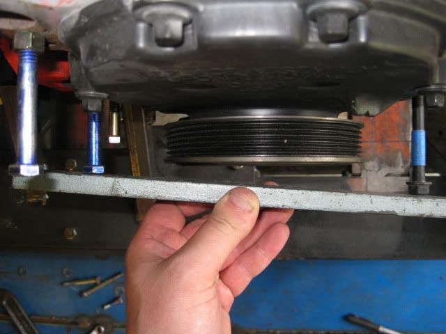
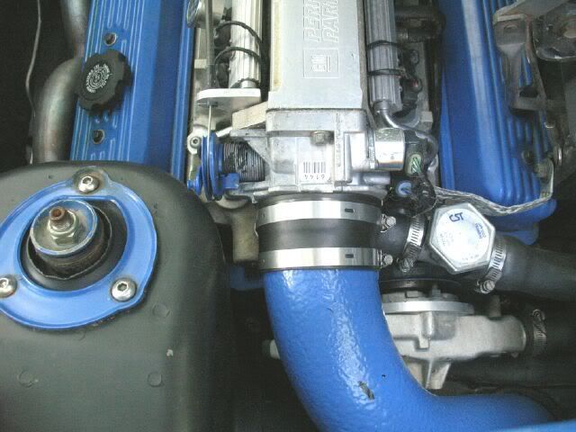
Also checked the clearance between the engine face and the passenger frame rail, then added 7/8" (distance saved with the thinner adapter plate) and this is the clearance I have to play with now:
I need to get the engine/tranny mocked up on the tubular cradle and test fitted in an 88 chassis to check the tranny side and see if the lowered engine position and moving the engine/tranny back to the passenger side about 1/4" will keep me from notching the driver side frame rail... keeping my fingers crossed.
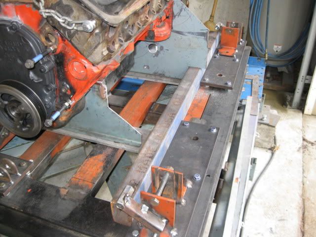
I went ahead and positioned the engine base on the SBC measurements on the fixture, but will probably move it further forward closer to the 4.3 location to allow more clearance at the throttle body/strut tower (flipped A/C and alternator allow this closer position). The engine elevation is 8 3/8" from the lowered cradle base, so the engine will be 1/2" lower with the new cradle.
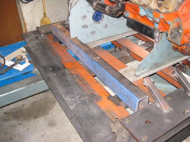
Went ahead and cut the front and rear 2x3x1/8" crossmembers. They are thicker than needed, but that is what I had in the metal pile and saves me from having to buy a length of 2x3. They are longer than needed, but I wanted to get them in place and notch the adapter plate for them. They are 24 3/8" inside to inside, but I will probably move the rear one forward another 1/4" to get it as close to the tranny as possible (allowing the most room on the other side for exhaust). Once moved forward, there will be about 1/8" clearance for the lateral link nut between the suspension bracket and the rear crossmember. Having the crossmeber this will not allow any auto transmission to fit an
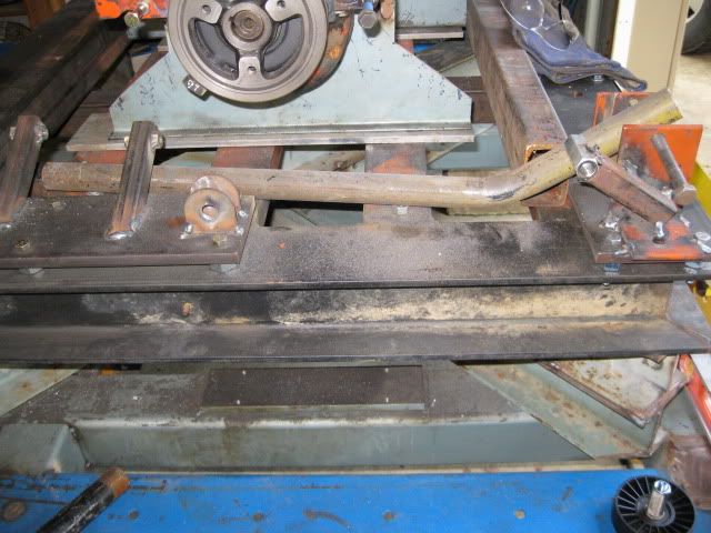
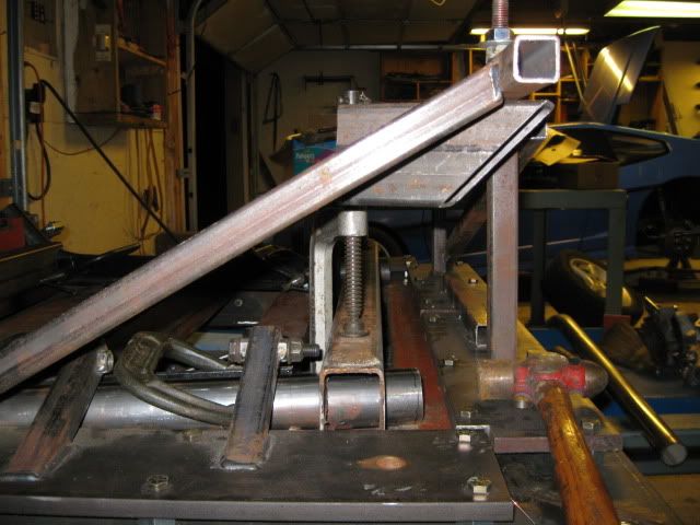
Here is a 1 1/4 diameter tube (spaced 3/8" up) being used for mockup purposes - figuring out how much to bend the 2" diameter tubes and the general route/shape of the side rail. The front and rear 2x3 tubes will be drilled/clearanced for the 2" round tube to pass through them.
I have saved the needed $225 to buy the adapter plate material and the round tubing for the cradle... just need to get out of work by 3pm on Monday so I can make the 1hr drive and be there before they close at 4:30.
IP: Logged
06:49 PM
rcp builders Member
Posts: 736 From: north port, Fl. Registered: Apr 2007
hey guru great work i,ve been lurking. I have a quick question, you say your centerline from your crank to center of cradle bolt is 15 1/8". Now archies web site says 16 3/8" but when i replaced my cradle and elongated tranny whole and used the second whole on the tranny bracket, my 350 wanted to sit better at about 15 3/8". In fact the p.o had set it at 15 3/8" because when i set it to 16 3/8" and fit it in the car i had to cut more trunk lid out to be able to close it. My motor is an 83 or so sbc i'm sure an inch is alot and i'm not sure if I should set it back to where it was or leave it at 16 3/8. Are your numbers what they are because it is an 88 mine is an 84. Thanx Ray
IP: Logged
11:06 PM
PFF
System Bot
Aug 2nd, 2009
fieroguru Member
Posts: 12127 From: Champaign, IL Registered: Aug 2003
When I converted to efi in 2005, I had to redo all my mounts to balance the clearances and to make the throttle body clear the strut tower (88). Had I raised the engine, I could have moved it to the rear some more, but I wanted it as low as possible to minimize the notch in the decklid to clear the top of the Ramjet intake.
There is no "right" engine location just a wide variety of where people place the engines to suit their install needs. Once you take on building your own mounts, you have a lot of freedom with engine placement. Using an electric waterpump or something custom like mine, increases this freedom to elevation as well since the waterpump snout no longer has to be above the frame rail for the belt drive.
I would put it where is best fits and get the engine level and square within the engine bay. Just need to remember that as the engine goes forward, your available room for belt tensioning with the alternator bracket becomes less and the alternator will hit the firewall sooner.
IP: Logged
07:04 AM
Aug 3rd, 2009
Isolde Member
Posts: 2504 From: North Logan, Utah, USA Registered: May 2008
Did you say you are or are not selling copies of that adapter plate? A guy in my local Fiero club wants to do a 350 to F40.
I will not be selling any adapter plate kits, but this one for $65: http://www.speedwaymotors.c...ter-Plates,3280.html will work in a similar fashion, but not have any provisions to rotate the tranny, starter mount or tranny mounts... but those can be worked around.
IP: Logged
06:38 PM
fieroguru Member
Posts: 12127 From: Champaign, IL Registered: Aug 2003
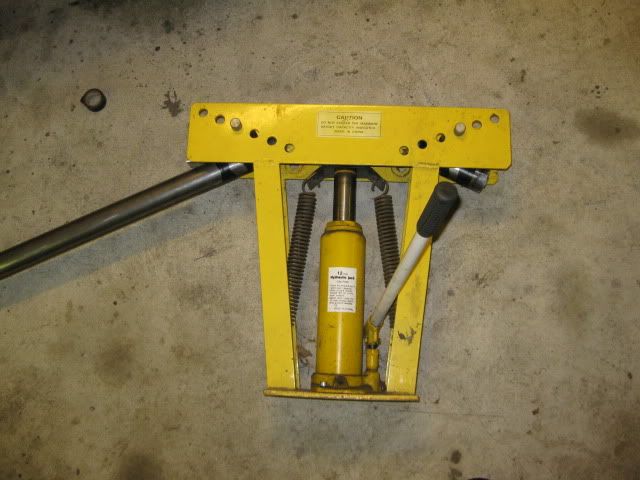
Now I need to find a local place than can bend it w/o any kinks. I checked with the dyno/machine shop 1/2 mile down the road and their bender would indent the inside of the bends. Still more places check... I might end up going old school on it and packing the tube with sand, heating the tube and bending it in my crude pipe bender.
IP: Logged
06:43 PM
Aug 4th, 2009
Isolde Member
Posts: 2504 From: North Logan, Utah, USA Registered: May 2008
It has been around for years... buddy of mine showed me the one he purchased at least 4 years ago, but until the F40 came along all it was good for was a pattern, because it was way too thin to be used for any FWD tranny.
IP: Logged
08:03 PM
fieroguru Member
Posts: 12127 From: Champaign, IL Registered: Aug 2003
I am kinda in a time crunch with the cradle. I can have access to an 88 engine bay early next week for mockup and clearance testing, so I really need to have the cradle tacked together so it can hold the engine/tranny.
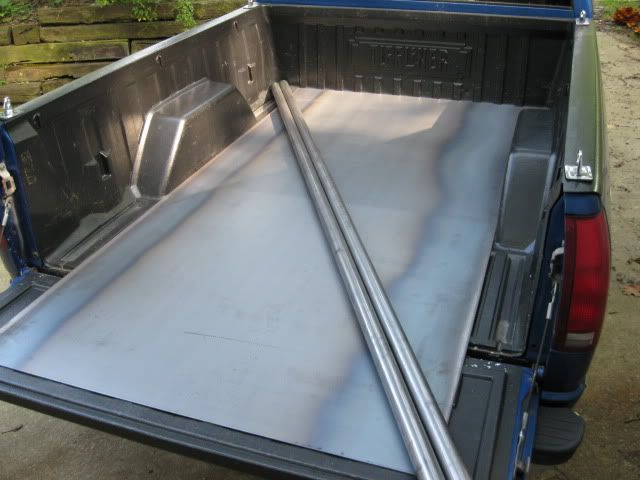
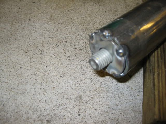
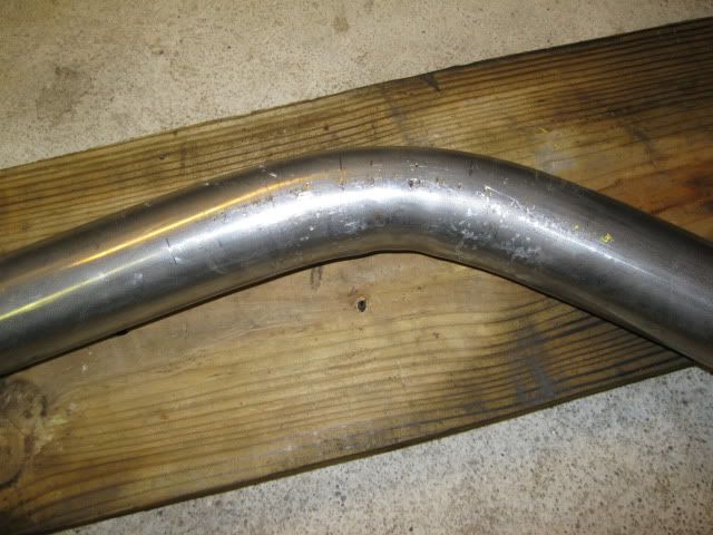
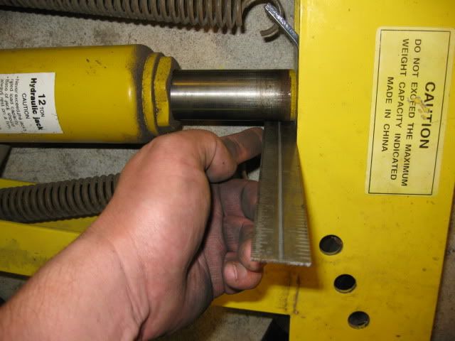
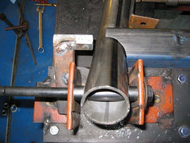
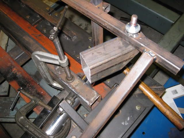
Welded some washers to the end of the tube and filled and packed it with sand before welding the other side. Then I gave my cheapo pipe bender a go at bending the tube w/o heat (torch would require taking everything with me about 50 miles away)... not perfect, but plenty good for my 1st cradle (probably will go in the 4.3 commuter car anyways).
I went ahead and put a bend at each end of the pipe (saves time from repacking another tube) and used a ruler across the head of the return spring bracket so I bent each tube to the same appoximate degree. I will check this once I cut the tubes and can tweak them slightly so they match.
[This message has been edited by fieroguru (edited 08-04-2009).]
IP: Logged
08:10 PM
Aug 5th, 2009
fieroguru Member
Posts: 12127 From: Champaign, IL Registered: Aug 2003
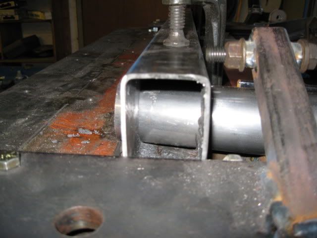
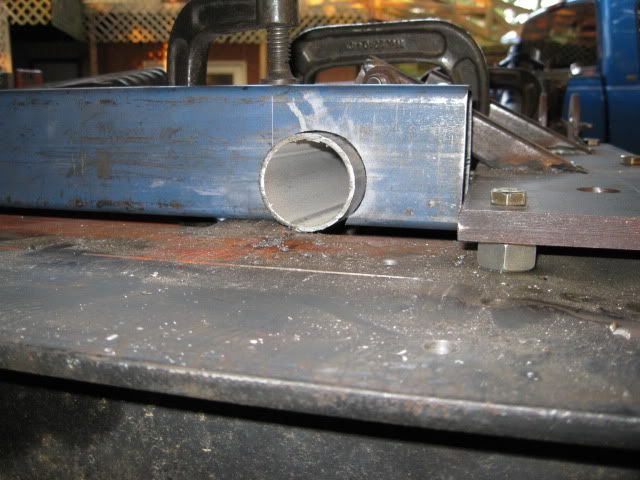
I ask because I have seen a couple of shots now where you're right on the edge of the material, such as the 2" wide remote water pump extension leg and the pass-thru tube for your cradle. If I tried a hole like the square stock tube with a regular twist drill and my sorry-a$s drill press, flex in the quill and/or sloppy bearings would let the bit walk sideways and ultimately come down next to the part.
Actually, you've been blasting quite a few holes through 3/8" and thicker it would appear... some of those holes on the base fixture seem to have appeared after being welded together, making me think you're not using a drill press for them
2)What kind of equipment are you using and how are you keeping it happy doing this quantity of drilling.
My drill bits would look like hell after doing that many holes, even with cutting lube and the slowest speed my drill press has.
IP: Logged
12:10 AM
fieroguru Member
Posts: 12127 From: Champaign, IL Registered: Aug 2003
2)What kind of equipment are you using and how are you keeping it happy doing this quantity of drilling.
My drill bits would look like hell after doing that many holes, even with cutting lube and the slowest speed my drill press has.
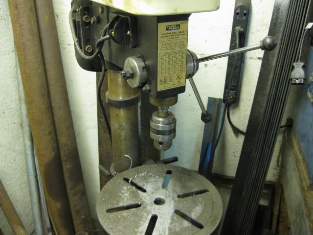
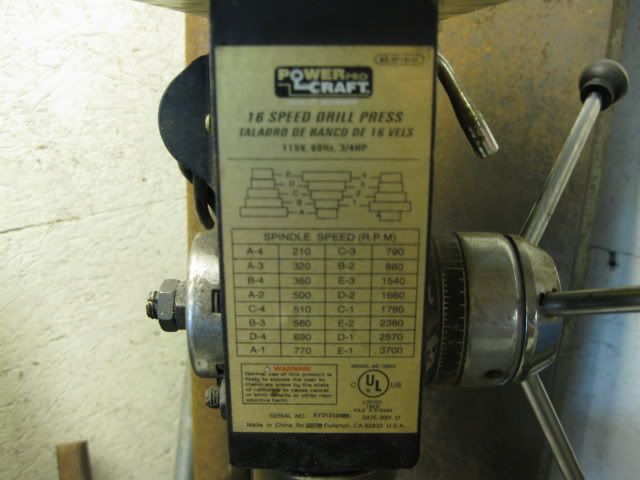
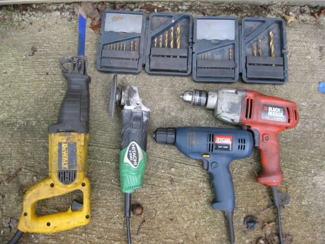
When possible, I use my 1/2" drill press - $160 cheapo from rural king. I need to replace the drive belts since they tend to slip - more so when cutting the holes.
For all hand held tools, I prefer to find the highest amperage at the lowest cost - I find the higher amperage ones do not burn up as often.
The next favorite is my Black & Decker hand held 1/2" drill - it is awesome. Then I also have a hand held Ryobi 3/8" drill with a hand twist chuck I use off an on when needed.
For cutting straight lines, I have an old Dewalt Saws All that rocks, a milwalkee14" chop saw that I rarely use, and a Hitachi 4 1/2" angle grinder with cut off disks (I wear this out atleast every 2 years - and kept fragging the gearboxes on the Dewalts).
For drill bits I have a 2 small sets of bosch guide tipped bits up to 3/8" and they are awesome and have seen a great deal of use - especially the 3/8" ones (36 holes in 1/2" steel, 39 holes in 1/4 to 3/8, and easily 20 holes in 1/8" or thinner... just on this project alone). I have had and been using these bits since 2007 and never sharpened them. I have had other sets that dull afer a couple of hole - so I only use them for the final hole size. To keep the holes properly positioned I always centerpunch the hole location and then start the pilot hole with a small (about 1/16") drill bit.
As you can see the tools are showing signs of years of use/abuse...
[This message has been edited by fieroguru (edited 08-09-2009).]
IP: Logged
07:27 AM
Aug 9th, 2009
fieroguru Member
Posts: 12127 From: Champaign, IL Registered: Aug 2003
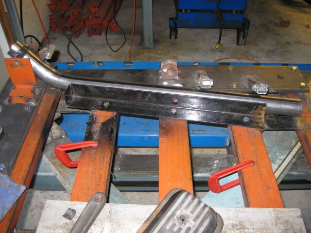
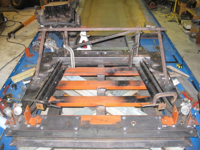
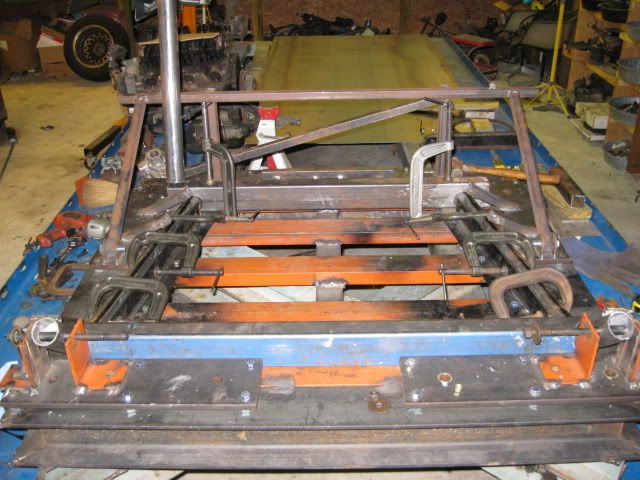
Spent a few hrs back focusing on the cradle. Finished drilling the other set of holes for the driver side rail:
Also, positioned and attached the angle support guide for the driver side rail, then positioned the rear crossmember and clamped it down:
I cut the tube for the front cradle bolts to length and then some drill guides. I still need to weld to the drill guides to the fixture so I can drill the two main tubes for the front cradle bolt sleeve.
Monday night will be busy, since I am planning on taking the cradle/engine/tranny to a friends house on Tuesday for a test fit and clearance check... the cradle will be far from done (no suspension stuff)... but should work fine for the clearance check.
IP: Logged
07:51 PM
fieroguru Member
Posts: 12127 From: Champaign, IL Registered: Aug 2003
My harbor freight pipe bender is not the greatest...
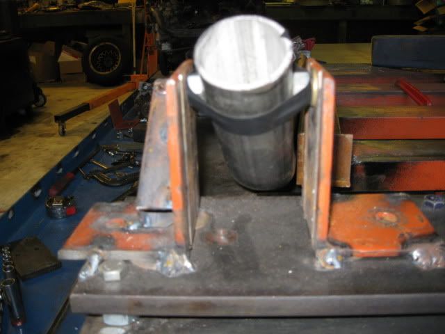
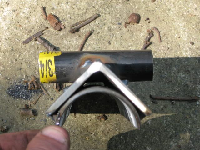
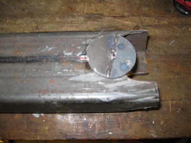
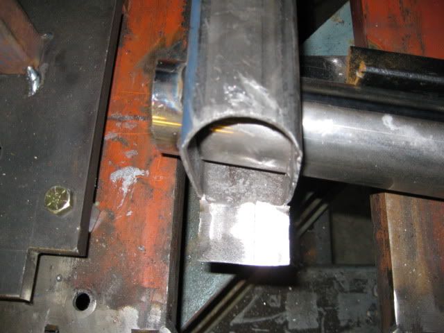
One thing I really do not like is the outer rollers the pipe is pushed against can dimple the tube if you do not put a thicker piece of steel on top of the tube. So I decided to make some new supports that will spread the load evenly on the top side of the tube and not dimple anything.
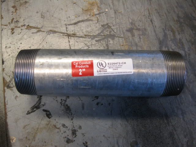
Piece of conduit just over 2" ID and cost under $7 at lowes.
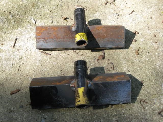
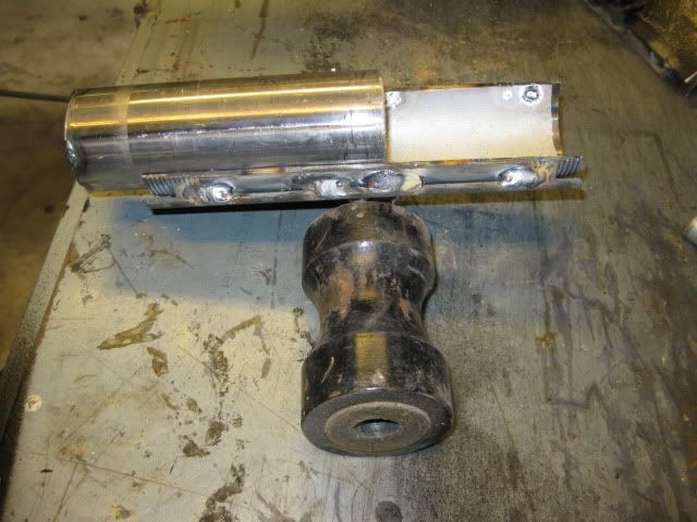
Then cut it in half, weld each half to some 2x2 angle for support and weld in a sleeve for it to pivot on:
Perfectly shaped die to support the 2" tube during bending.
[This message has been edited by fieroguru (edited 08-09-2009).]
IP: Logged
07:57 PM
cptsnoopy Member
Posts: 2585 From: phoenix, AZ, USA Registered: Jul 2003
Good stuff! I have a bender very similar to yours and you are right, it is a pita to get a good bend without crunching some pipe.
Charlie
Someday I will add a torch to my bag of tricks. I think heating the tube while it is filled with sand would allow my cheapo bender to make some decent 90 degree bends.
IP: Logged
09:48 PM
fieroguru Member
Posts: 12127 From: Champaign, IL Registered: Aug 2003
Drilled the main tube for the cradle bolt sleeve (and broke a 15/32" drill bit - torquey 1/2" hand drill) on both sides and then went about fitting the 2x3 front crossmember. I have the passenger side countured, but still need to do the driver side. Cradle #2 will be all 2" round tube, making all these notches is way too much work!
Assembling this cradle is getting to be like a 3D jigsaw and I can not tack anything into place until all the parts are fabricated and fitted. The cradle is not going to make the planned fitting date for Tuesday, I would rather take my time and make it right. I can always pull the engine from one of my 88's to do the test fit later.
IP: Logged
09:56 PM
Aug 12th, 2009
fieroguru Member
Posts: 12127 From: Champaign, IL Registered: Aug 2003
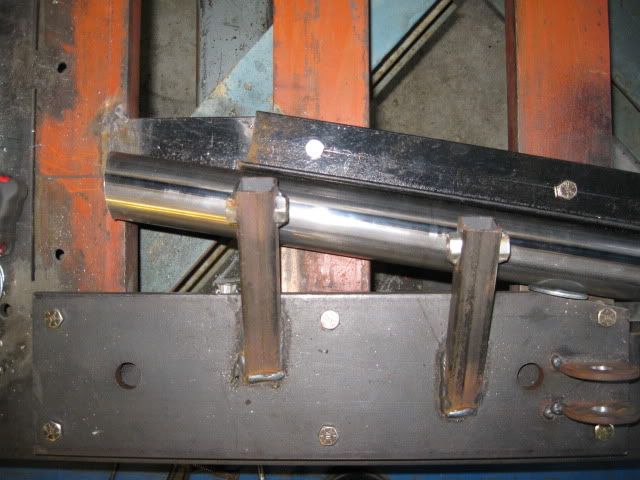
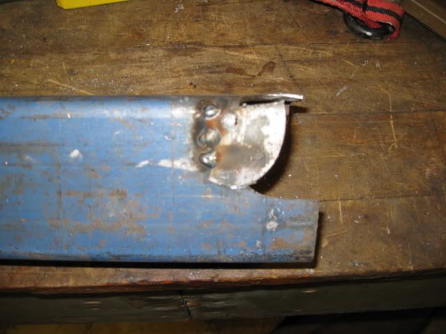
Finished the driver side of the cradle. Fitted the notches with the crossmember too wide, then transferred the contours to the proper location and it actually fits! The only challange I had was after transferring the contour, the pilot for the holesaw was right on the edge of the previous countour... so took some of the holesaw scraps and welded in the needed pilot hole:
Here is the driver side with the crossmember and both main rails installed:
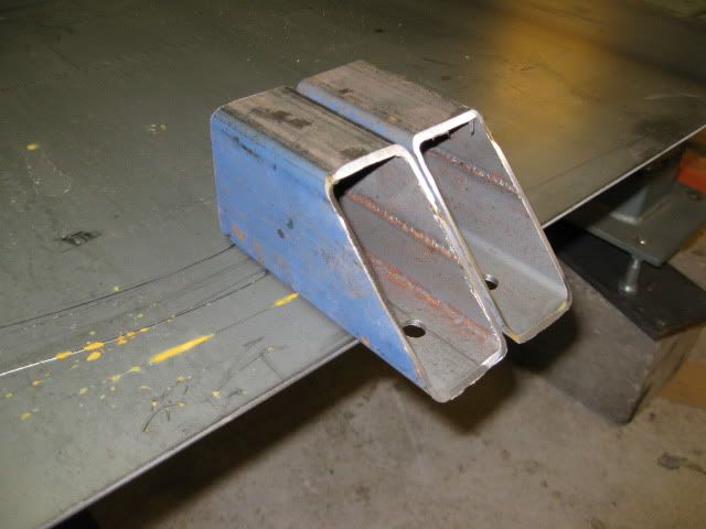
Then started on the upper mount pads. Been thinking about these for a while and settled in on using some 2x3 with a 45 degree cut to access the bolt hole from the bottom. These are still rough shaped and I will notch these as well as the lower crossmember for the 2" tube that will eventually connect them.
I have an opportunity to test fit early on Saturday, so I will probably just tack in some temporary angle for the rear cradle locations just so I can place the cradle up under the car.
In case anyone wonders what all the silver looking stuff around the holes is... it is antisieze... works wonders to lubricate the holesaw bit as it cuts through the metal.
[This message has been edited by fieroguru (edited 08-12-2009).]
IP: Logged
09:48 PM
Aug 13th, 2009
cptsnoopy Member
Posts: 2585 From: phoenix, AZ, USA Registered: Jul 2003
Worked on the rear cradle till 2:30 am and have it all tacked together for the test fit this morning (suspension pickups still need to be completed). Right now it weights 38lbs and I will add a few more lbs with the finish welding and the suspension tabs. I think it will end up +/- 5lbs from stock.
Sorry no pics, internet at home was being flakey and my work PC doesn't like my camera.
IP: Logged
07:22 AM
PFF
System Bot
Aug 16th, 2009
fieroguru Member
Posts: 12127 From: Champaign, IL Registered: Aug 2003
Internet is still flakey at home, but here are the pics anyway.
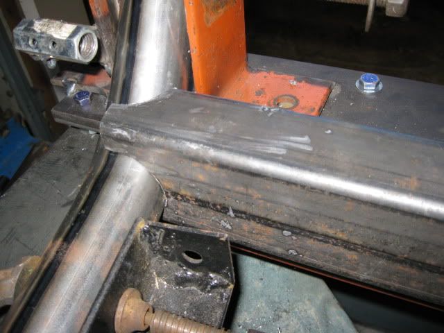
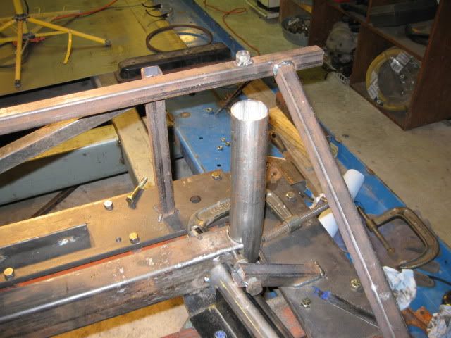
Finished up the rear uprights on Friday night. The rear crossmember was notched to accept the upright tubes:
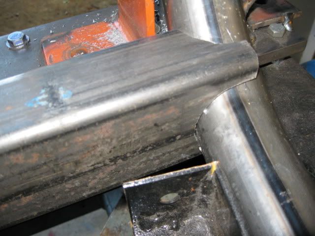
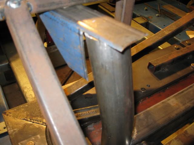
Then it was a matter of fitting the 2x3 upper sections to the upright tubes. If you go to fast and do not measure correctly, you can end up with a nasty gap like this:
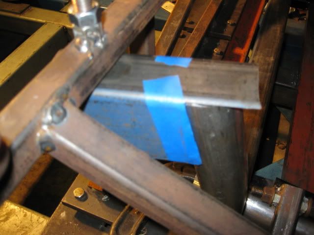
Best thing to fix it is use some tape to identify the proper cut line and then remake the piece.
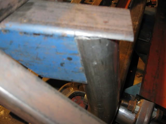
All better now:
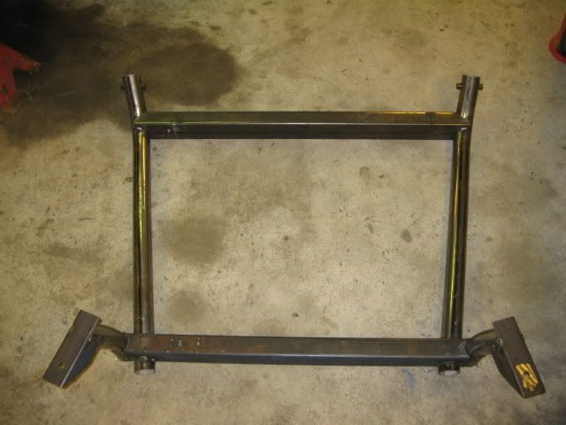
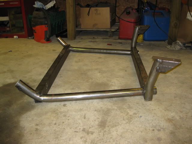
Tack the whole thing together and you end up with a tubular cradle...
It weighs 38 lbs as shown in the pics above. The suspension links need added as well as the cradle being fully welded, so I should end up close (+/- 5 lbs) to the 50 lbs of a stock cradle
IP: Logged
09:26 AM
fieroguru Member
Posts: 12127 From: Champaign, IL Registered: Aug 2003
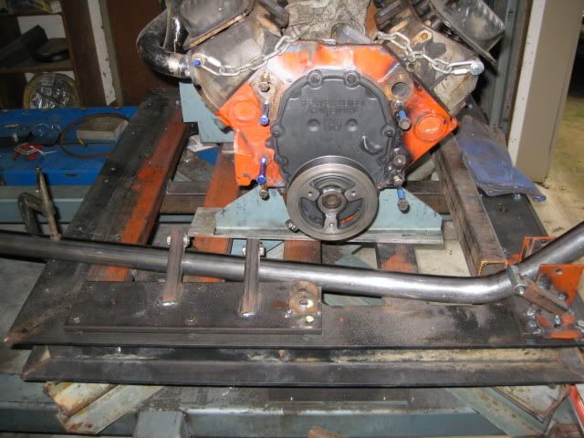
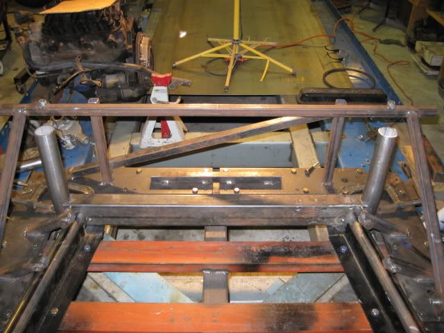
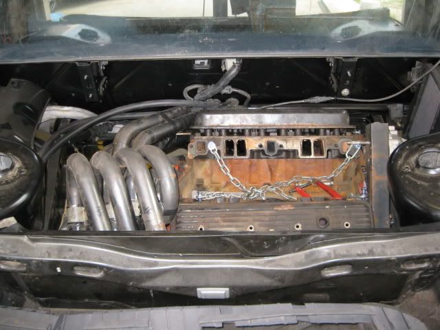
Moment of Truth... test fitting to see if all the effort so far will result in a SBC/F40 combo that will fit within the stock framerails - without any cutting, denting or modifying. Short answer is a resounding YES!
Cradle by itself in the chassis:
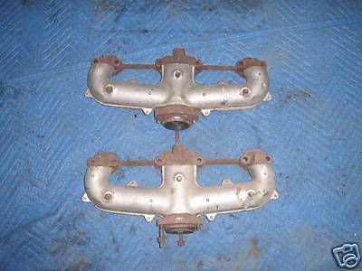
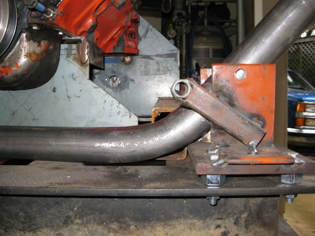
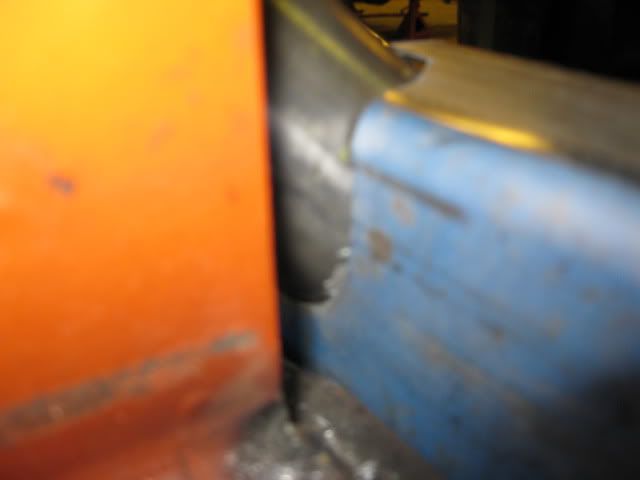
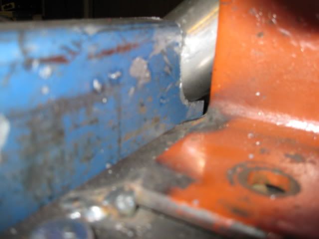
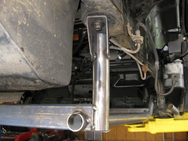
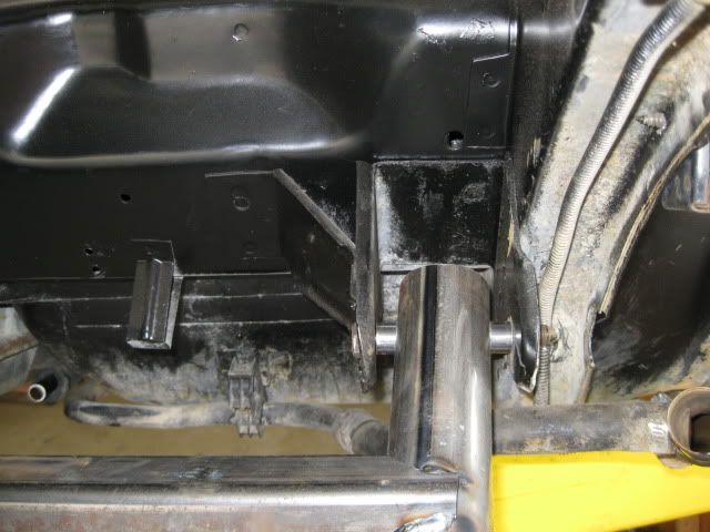
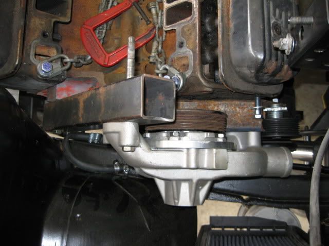
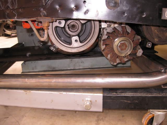
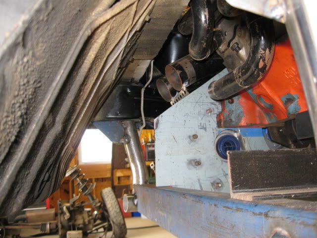
Engine in. Tightest spot on the passenger side is the clearance between the bolts on the rear offset housing and the passenger frame rail. I might just recess these bolt heads to gain more clearance (my SBC car does not have the fuel lines running down this frame rail like shown in the pic)
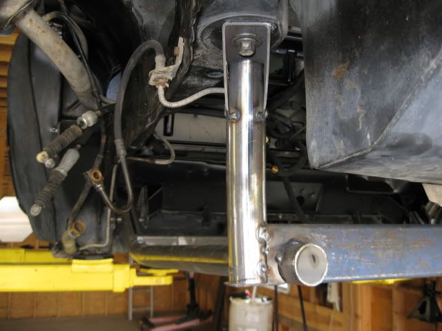
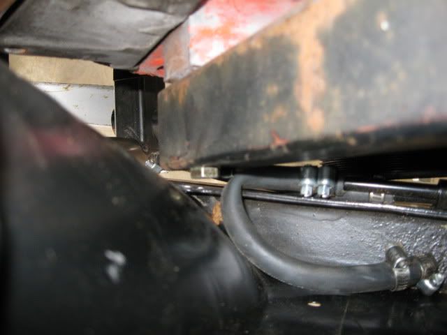
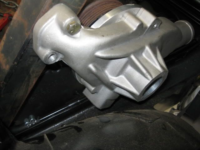
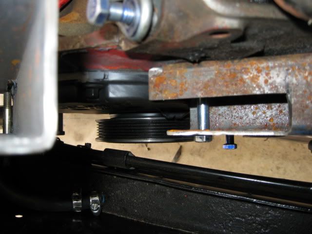
Waterpump in place: Balancer to frame rail:
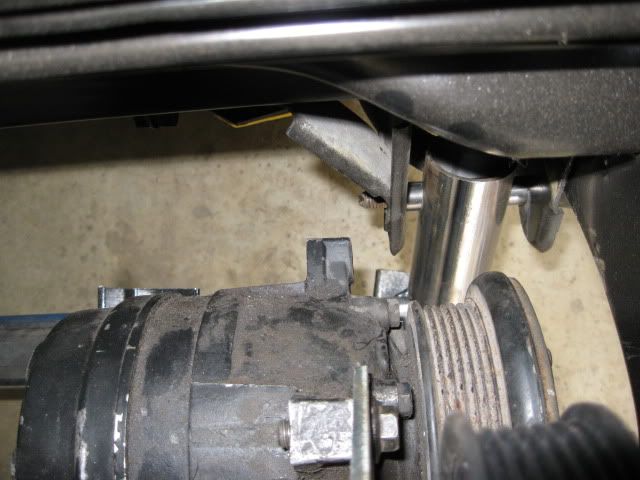
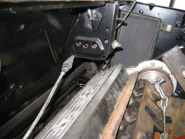
AC compressor to firewall:
Alternator to cradle rail:
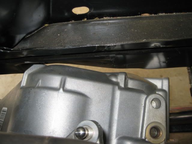
Valve cover to deck lid hinge bracket. Many SBC's cut this bracket to clear the valve cover and it is a good indicator of how low my engine is:
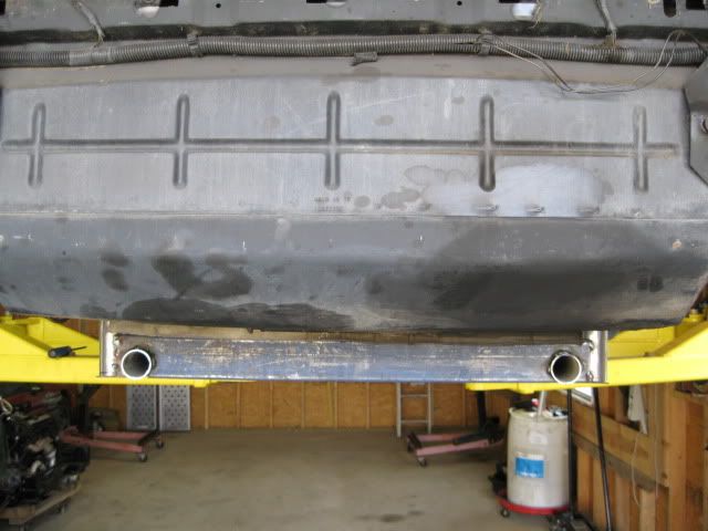
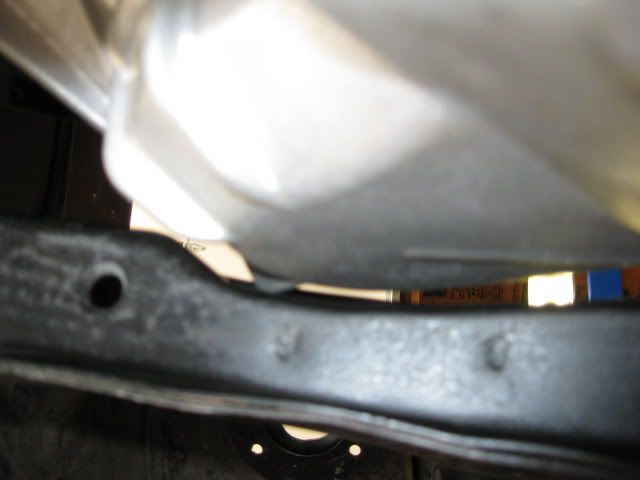
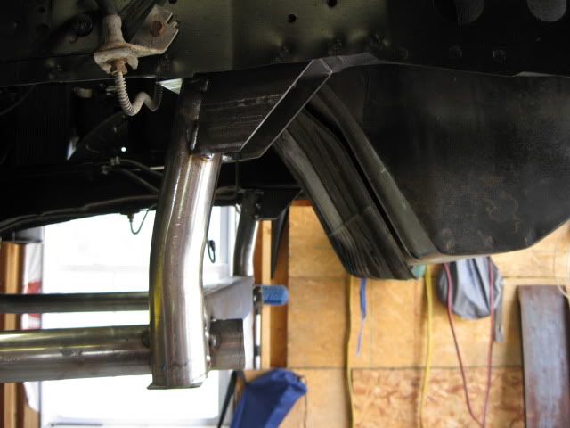
Tranny to driver side rail. The factory recess in the frame rail is just about the perfect shape needed to clear the F40:
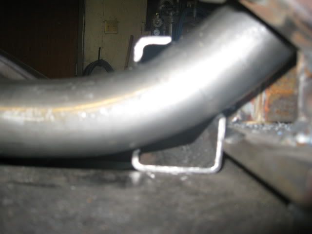
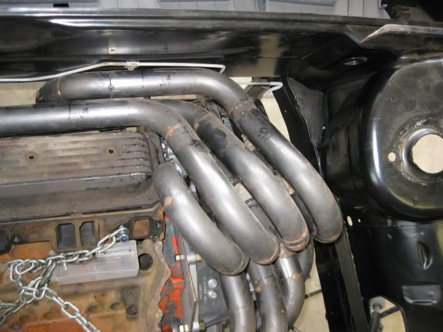
Look at all this room for an exhaust:
The engine placement front to rear can and will go another 1" towards the front. This will provide more clearances at the frame rails on both sides, enlarge the exhaust area and give me more side to side freedom for engine placement (hoping I can make the stock 9-5 passenger axle work as a bolt in solution.
IP: Logged
09:48 AM
cptsnoopy Member
Posts: 2585 From: phoenix, AZ, USA Registered: Jul 2003
I am not sure how much progress will be made in the coming weeks. After 3 years in the current house/garage it is time to move to another... We take possession at the 1st of Sept and have to be out of the current place by 30th of Sept... so for the next several weeks I will be in packing/moving mode.
IP: Logged
07:42 AM
Aug 26th, 2009
1986GTV8 Member
Posts: 1259 From: Orlando,FL,USA Registered: Mar 2002
Thanks! Not much to show right now. I have the cradle mostly welded up, but still need to work on the caps for all the tube. Then I will move on to the suspension locations. But probably will not get much done on it over the next few weeks... starting Sept 1 I will be moving all my stuff abotu 25 miles up the road to our new house.
quote
Originally posted by GTCONVERSION:
If you ever want to sell a sey of those headers you make im first to buy!!
And what price would you be willing to pay? Material cost is $300+ before having them coated (add another $300 to $500) and then factor in all the hrs of labor for the fitting, cutting, welding, grinding, etc and the cost for a replicated set could easily be in the $1500 to $2000 range even if I only charged $10 an hr for labor.
I highly doubt there will be another set produced, unless I am building them for one of my cars.
IP: Logged
08:36 AM
Isolde Member
Posts: 2504 From: North Logan, Utah, USA Registered: May 2008
I am not sure how much progress will be made in the coming weeks. After 3 years in the current house/garage it is time to move to another... We take possession at the 1st of Sept and have to be out of the current place by 30th of Sept... so for the next several weeks I will be in packing/moving mode.
Congratulations on the house.
I have a couple of questions. How much TQ do you think your cradle will handle? Can you remove the valve cover with out dropping the engine? (I didn't cut my hinge box but I cant remove the valve cover)
Thanks for posting, wish I had a place to work on cars like that.