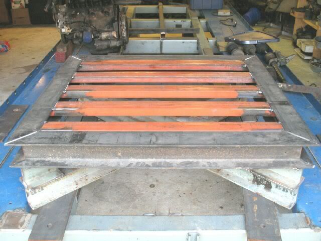
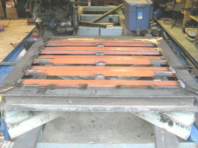
Nope, just mechanical engineering and a MS in efficient mfg methodologies (both of which I am ignoring at the moment). The material was free and weight is not an issue since it will only be moved a couple times a year. I am more concerned with defection than strength, so why not overkill it... Here is the underside completed:
and flipped over:
IP: Logged
07:18 PM
Apr 21st, 2009
Isolde Member
Posts: 2504 From: North Logan, Utah, USA Registered: May 2008
Fieroguru, Thanks for the PM a month ago, I just found it. I just sent you an unrelated but urgent one, I tell you here in case you tend to accidentally overlook your PMs the way I do. And the over-engineering just noted by someone else is far preferable to me as opposed to under-engineered. I say not just over engineered, but it looks slightly over-built as well. Excellent!
IP: Logged
04:35 PM
fieroguru Member
Posts: 12128 From: Champaign, IL Registered: Aug 2003
Fieroguru, Thanks for the PM a month ago, I just found it. I just sent you an unrelated but urgent one, I tell you here in case you tend to accidentally overlook your PMs the way I do. And the over-engineering just noted by someone else is far preferable to me as opposed to under-engineered. I say not just over engineered, but it looks slightly over-built as well. Excellent!
I PM'd you back (I check mine couple times a day when I am around the computer) and might have something that will work.
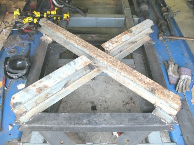
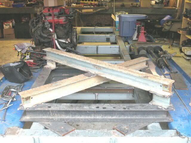
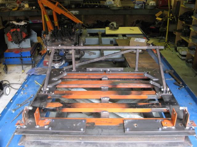
One of my vices is being a packrat - especially when it comes to steel material. To keep costs down, the cradle fixture had to be built with material on hand, so I had the choice between 2x2x1/4" angle, the orange 2" C-channel or the 4x4 I-beam. Aside from the cradle fixture, I do not any any needs for anything that would take the 4x4 I-beam (already built the frame rack - that the cradle fixture is sitting on) so might as well make it useful for something. The light blue 4x4 I-beam was from a 1967 asset that was removed in 2003 and had been sitting outside ever since - now the pile of it is much less.
Yesterday I got the angles cut from the C channel that will be the crossmembers, still need to cut them to length, make the appropriate notches and holes so they can be clamped in place for welding. I ran out of welding gas and am not planning on getting anymore till after the Fiero Factory Swap Meet this weekend.
IP: Logged
06:16 PM
Apr 29th, 2009
fieroguru Member
Posts: 12128 From: Champaign, IL Registered: Aug 2003
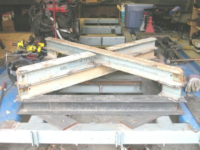
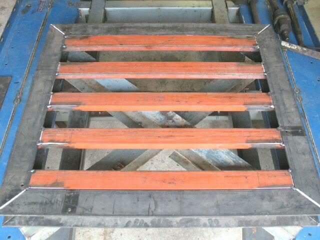
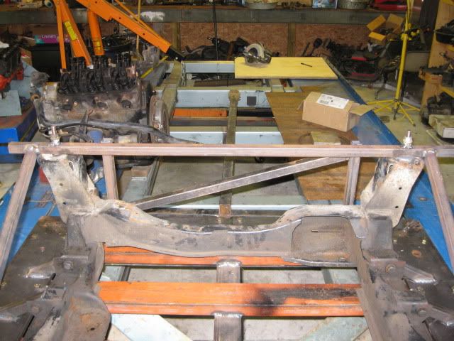
Got the rest of the crossmembers cut and tacked into place. Now I just need to finish welding the joints and it will be time to start mocking up the cradle and suspension bolt locations.
IP: Logged
07:19 PM
May 3rd, 2009
fieroguru Member
Posts: 12128 From: Champaign, IL Registered: Aug 2003
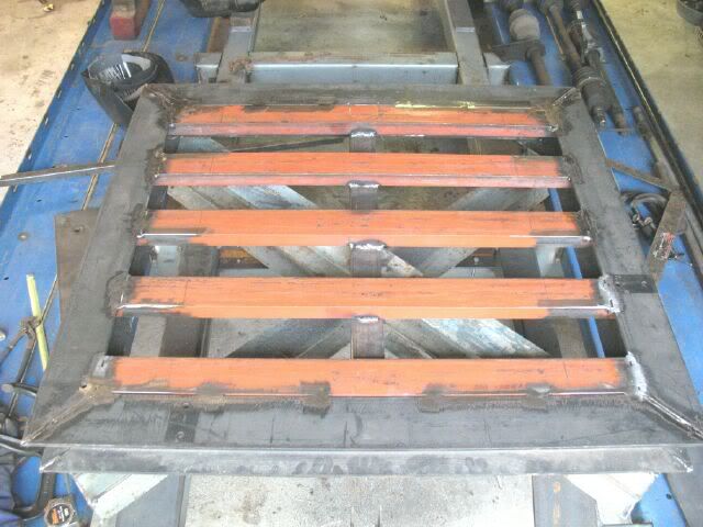
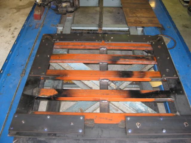
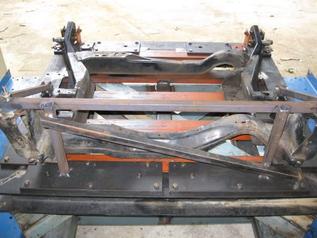
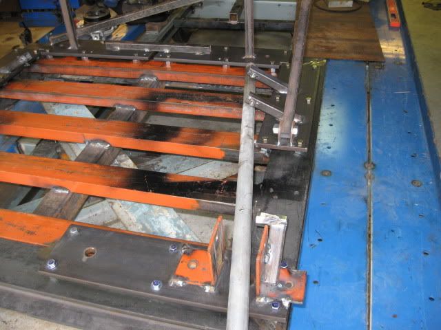
Put the last central crossmember in. It connects all the orange crossmembers in the center.
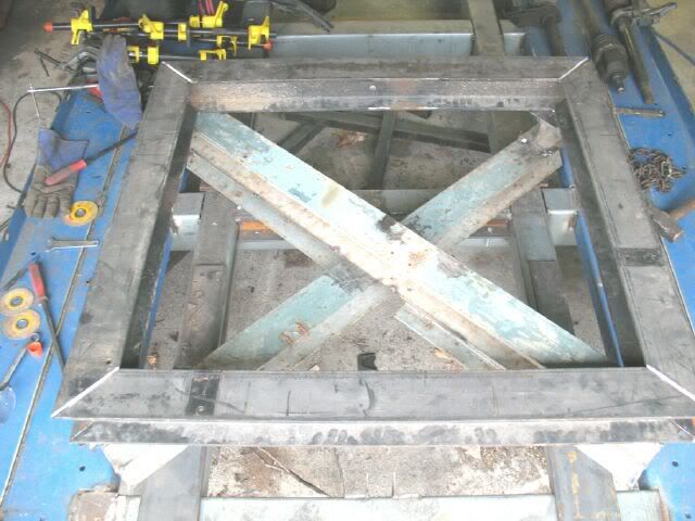
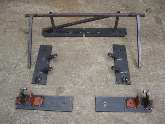
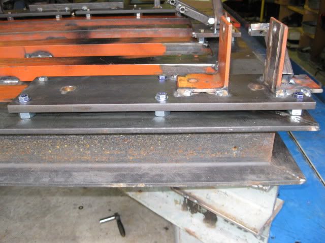
Next step is to make the flat plates that will bolt to this fixture and then have the brackets for the bolt locations welded to them. I have several of these pieces of 1/2" plate and will use 4 of them for the front crale bolts and suspension links.
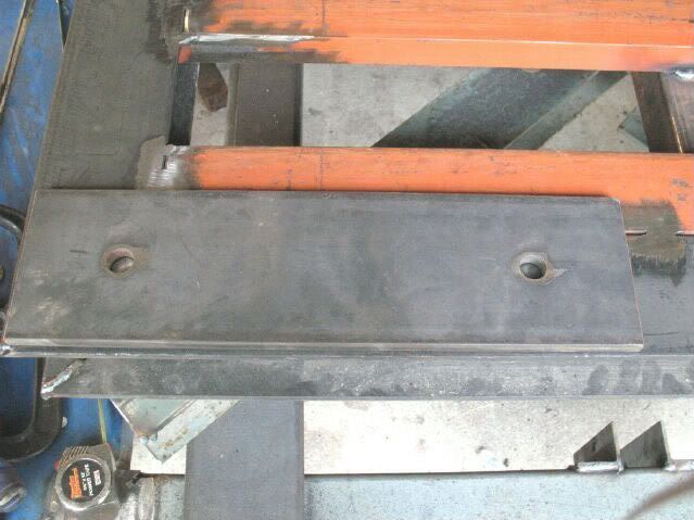
Six 3/8" bolts will hole each into place, so I measure out and pilot drilled one and will use it as a pattern to make the other 4. Also took that 1st one and pilot drilled all the holes in the fixture. These will eventually be drilled larger and tapped for the 3/8" bolt.
Probably will be a week or two till I am back on this project.
The wife and girls are leaving for Chicago for a week and I will be baching it. During my bach time, I will be focusing on finishing up a 4.9 swap for a friend.
IP: Logged
05:53 PM
Jun 14th, 2009
fieroguru Member
Posts: 12128 From: Champaign, IL Registered: Aug 2003
Still bogged down with the 4.9... but did do a couple of things today.
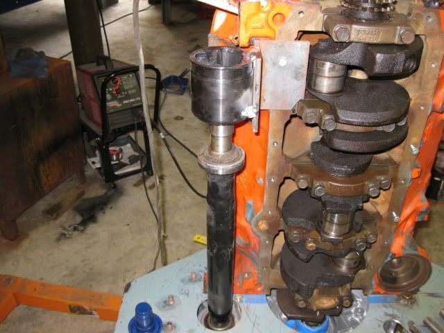
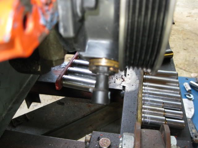
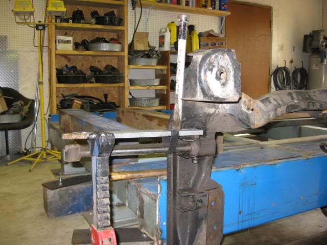
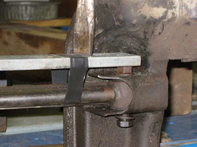
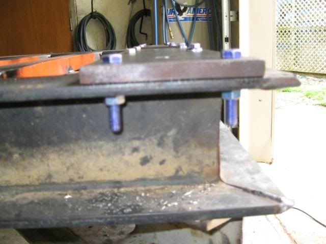
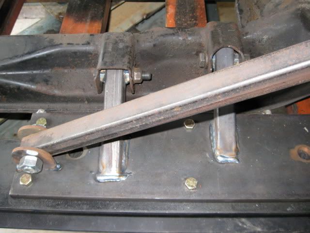
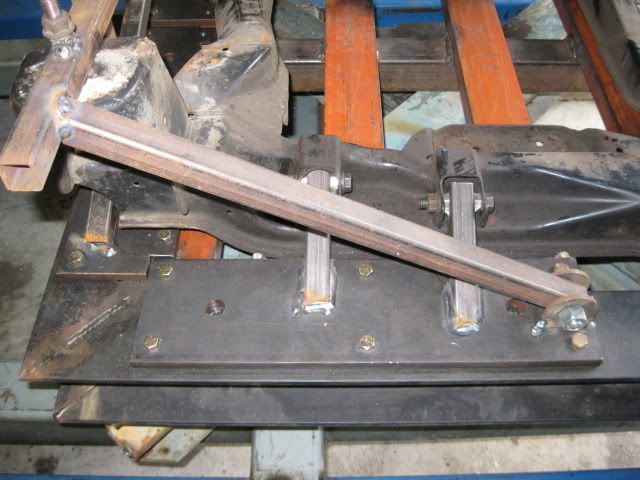
My spare cradle had a couple of bolts that were rusted in the sleeves (the rear lateral links on the cradle). After a few weeks of soaking in PB blaster, I setup to pound them out. With the cradle up on end and clamped to my frame rack, I setup a jack stand to support a steel bar that would span between the jack stand and the bolt to be removed. The black electrical tape holds the bar in place between stikes and the chisel by the cradle is wailed on by the mini sledge.
After about 10 smacks the passenger side bolt came loose and has been remove:
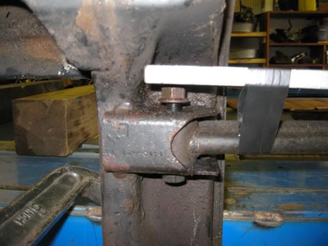
The driver side is still being stubborn even after about 50 smacks... I will let it soak another week or two:
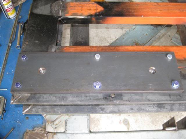
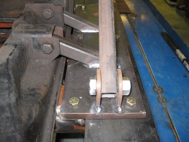
Then I drilled all six 1/2" plates that will bolt to the cradle jig and got the front 2 mounted:
I will probably weld the heads of the bolts to the plates to make them into studs. Then to lower the bottom of the cradle I just shim up these plates.
[This message has been edited by fieroguru (edited 06-14-2009).]
IP: Logged
06:32 PM
Jul 3rd, 2009
fieroguru Member
Posts: 12128 From: Champaign, IL Registered: Aug 2003
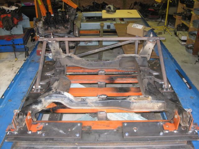
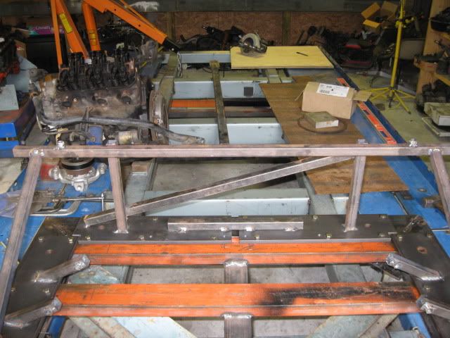
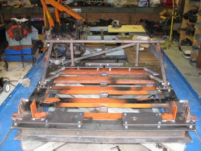
The 4.9 left the building last Sunday, so I am back on the cradle fixture and am pleased to say it is done!
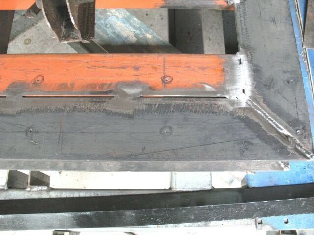
All the steel plates were finished and mounted:
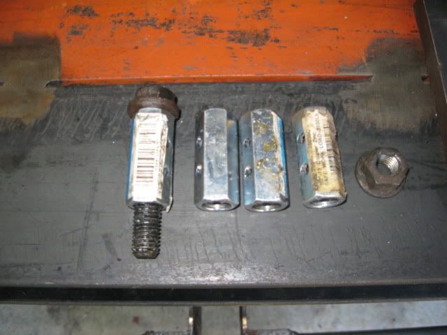
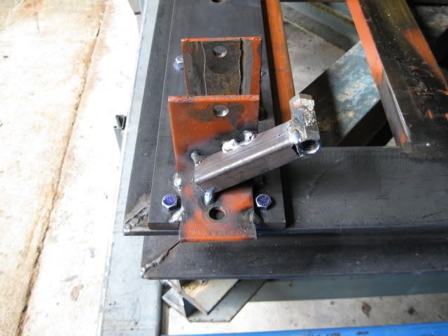
Took some threaded couplers (1/2" and 5/8") and drilled them for a snug fit on the metric bolts in the lateral links (the 1/2' ones) and the trailing arm (5/8" ones):
With some 1/4" spacers welded to the inside of the side plates, the cradle is snug side to side sittign down inside the side plates. Next, I positioned it front to rear where I wanted it and clamped the cradle down to the fixture.
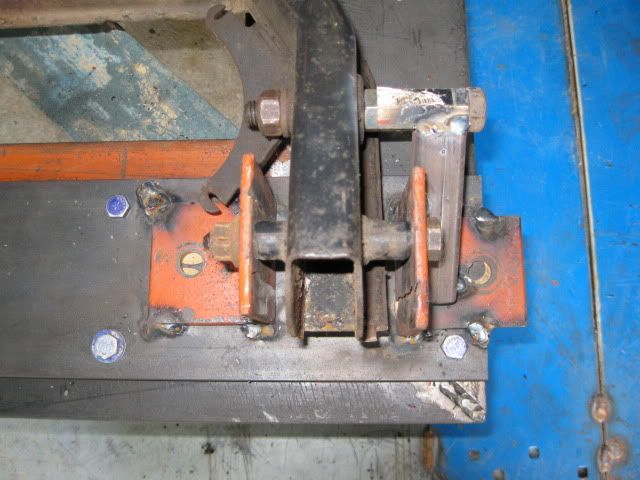
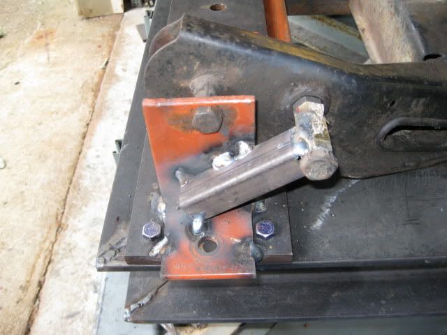
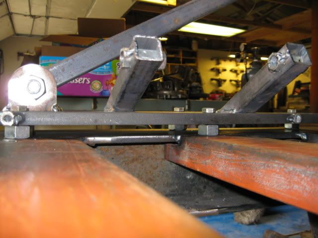
Then it was a matter of drilling some scrap angle for the front cradle mounts, welding some1x1 to the 5/8 couplers and properly position them and weld the brackets for the front cradle bolt locations and the trailing arm. Call me a perfectionist, but I made sure that the cradle was square on the fixture and the front cradle holes were the same elevation and the inside distance from the outer brackets matches the measurement in the 88 service manual...
The lateral links were next with the 1/2" threaded couplers inserted into a drilled hole in the 1x1 tube and welded to the tube. Then the plate ends were cut at an angle to spread the weld surface out. I made sure all these angles were the same and all the elevations of the lateral bolts are at the same elevation as well.
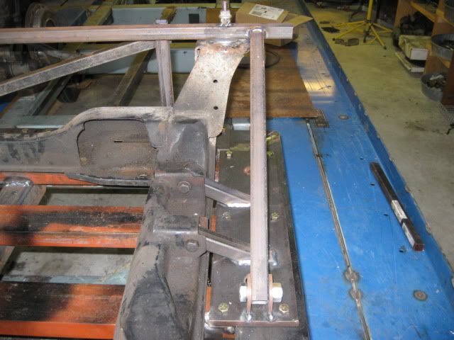
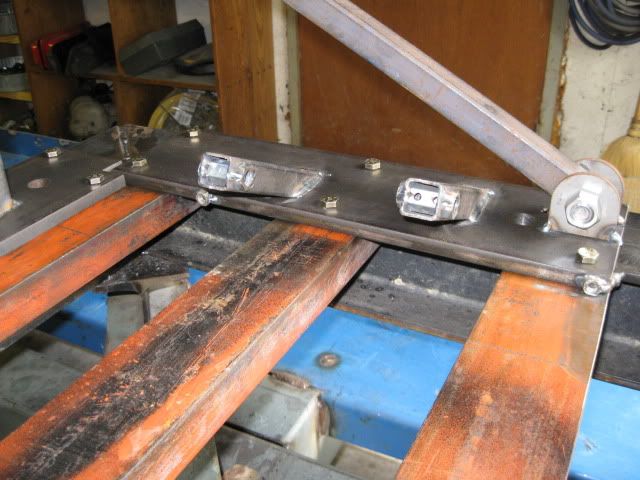
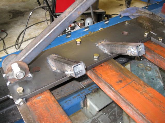
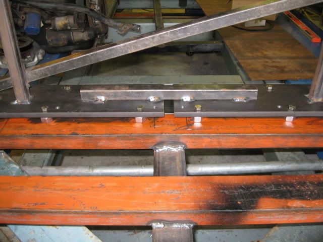
For the rear cradle bolt hole locations, I started with a 1x1 tube and drilled the 2 holes for the threaded couplers to the distance in the 88 service manual. Lined up with the bolt holes in the cradle perfectly. Then I spent about an hour leveling the mount pad location on the cradle and checking and rechecking the elevation of these holes. The base of the cradle is flush on both sides, all the suspension locations at the same elevation side to side, but the elevation of the rear cradle mount pads are 3/16" different side to side... gotta love GM quality control. So I added a washer to the top side of the short one to level the 1x1 mount bar. Then installed the uprights to maintain the proper elevation, a diagonal link to keep them positioned side to side and added the 2 front braces that bolt to the lateral link plate to control deflection front to rear. When it was all clamped together, checked everything for square and level and welded it up.
All done:
On Saturday I will unbolt the steel plates and remove the cradle and take some pics of just the fixture assy.
IP: Logged
05:22 PM
Jul 4th, 2009
fieroguru Member
Posts: 12128 From: Champaign, IL Registered: Aug 2003
I need to run out to the hardware store to get the 1/2" spacers, then everything will be shimmed 1/2" higher which will lower the base of the cradle by 1/2" while keeping all the cradle mounts/suspension locations in the stock relationship.
IP: Logged
11:15 AM
PFF
System Bot
fieroguru Member
Posts: 12128 From: Champaign, IL Registered: Aug 2003
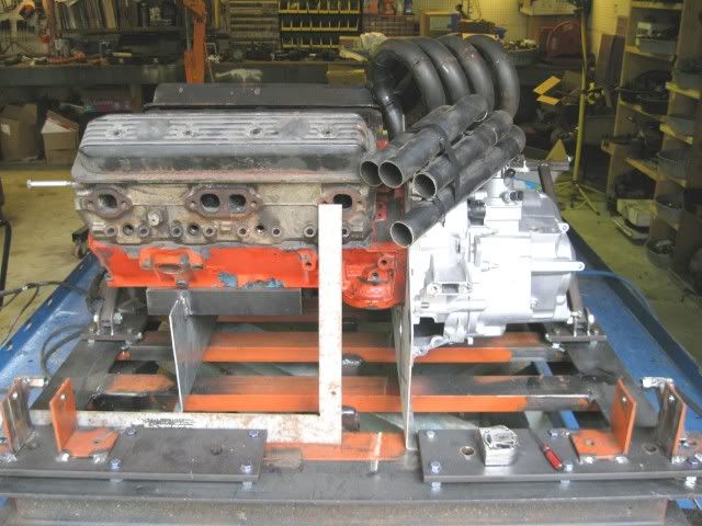
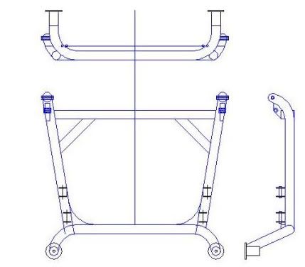
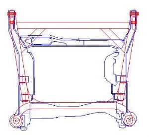
Here is a scrap piece of pipe just roughly positioned in the general direction of the main cradle rail, I will probably have to cut the corners off the side plates to clear the 2" diameter main rail tube.
Now I need to start checking around locally to see if anyone can do custom mandrel bends... If not, I will have to revert to filling with sand and using the torch with my hydraulic pipe bender...
That is it for today.
[This message has been edited by fieroguru (edited 07-04-2009).]
IP: Logged
02:04 PM
fieroguru Member
Posts: 12128 From: Champaign, IL Registered: Aug 2003
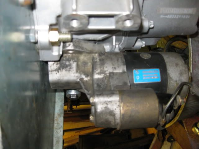
Well everyone was taking a nap, and I hate to waste a nice day in the garage, so back out I went and changed gears to the starter mockup.
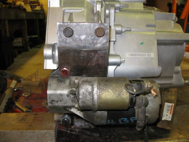
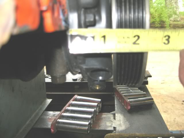
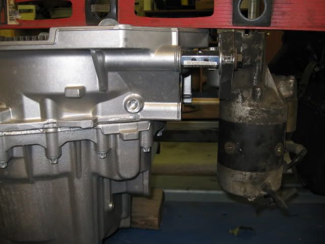
Looking over the stock bolt bosses on the tranny, one of them was real close to being in the proper position for the Maxima starter, so I used a long bolt and needed spacer and put the starter into rough position.
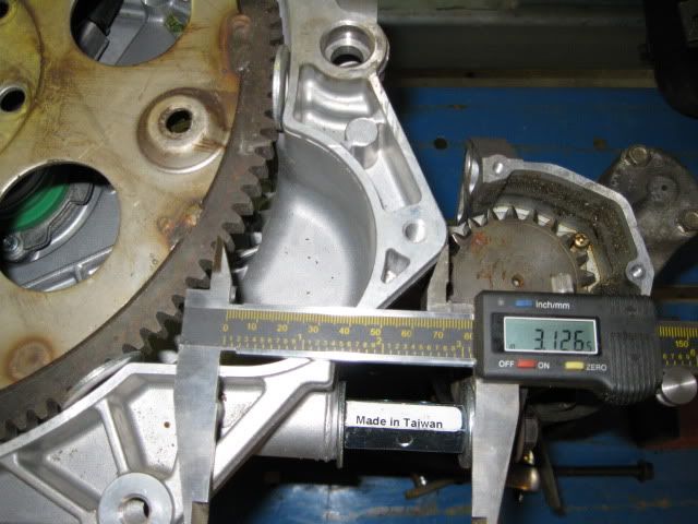
For the pinion to properly engage the ring gear, the starter needs to be about 3 1/8" closer to the tranny:
The face of the starter is also just under 1/4" from the bellhousing face, so using this hole will require moving the ring gear further away from the engine (just some lathe time).
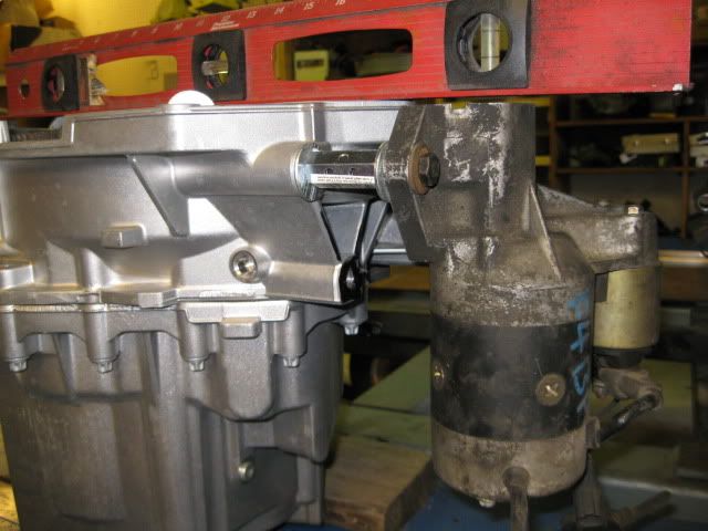
My spacer in the pic is just under 2" long, so the stock bolt boss would need to be drilled/threaded deeper and then cut down about 1 3/16" - it would still have plenty of material left to hold the starter tight.
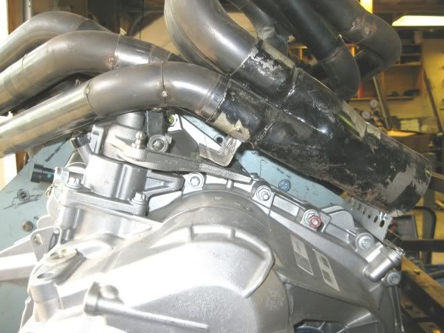
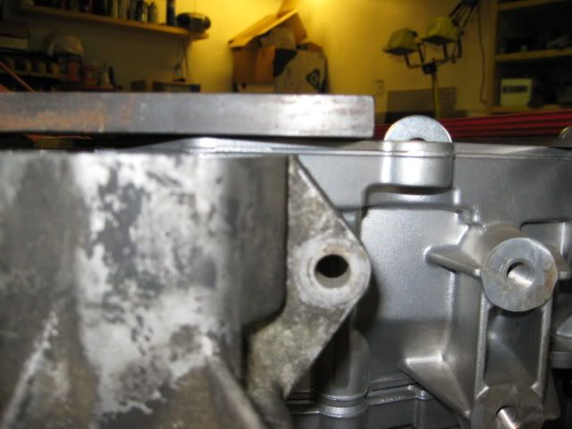
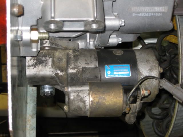
The good news is there is just enough room between the starter body and the protruding edge of the case flange. The piece of steel in the pic is 3" wide and there is about 1/8" clearance. The protruding portion of the flange could also be clearanced another 1/8" without much issue.
Taking the 3" piece of steel and placing it on top, there is a slight issue. The upper flange for the starter will interfere with the ring gear. This flange is angled down, so we are probably talking about 1/8 to 1/4" interferance at a portion of the starter flange.
The upper two bolt bosses would most likely be cut down to be flush with the backside of the starter flange so a bracket can come from them and bolt to the backside of the starter flange. This could complicate the upper starter bolt - either it would need to be a stud, tightened with the starter/bracket off, ot just tap the starter hole.
Another option would be to mount the starter via small brackets from both the upper and lower holes and shift its location to eliminate the 1/4" gap to the bellhousing flange, shift it up slightly so it does not have to go in as far, to gain clearance to the ring gear, and to allow it to be mounted at a slight angle (to further gain clearance to the ring gear).
Still quite a bit of stuff to figure out, but mounting this starter in this general area will probably be my route... just need to have the guts to cut up the tranny.
IP: Logged
03:59 PM
ethan555 Member
Posts: 275 From: abilene, tx, USA Registered: Jul 2008
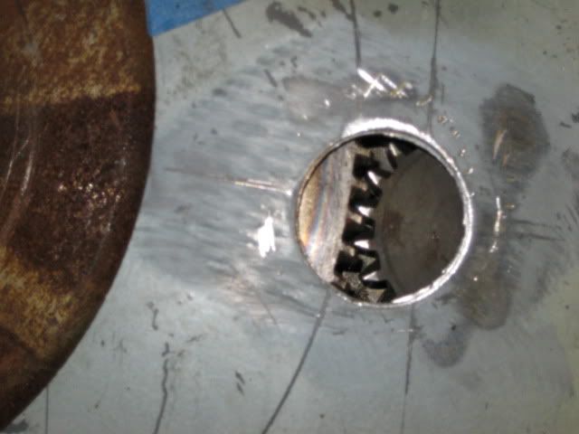
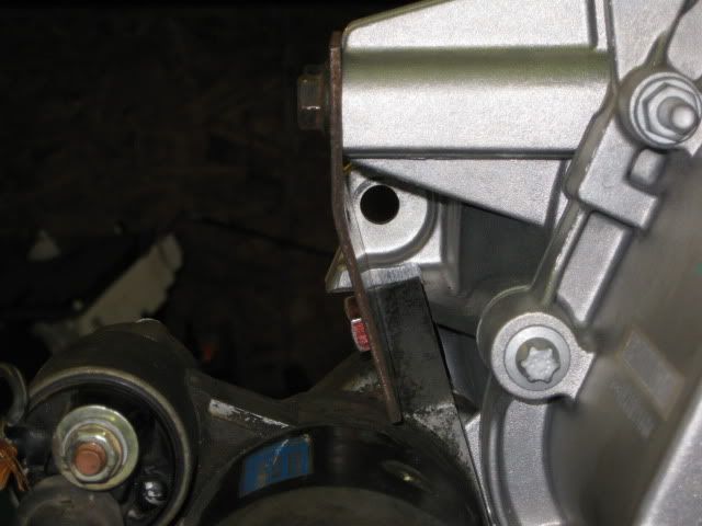
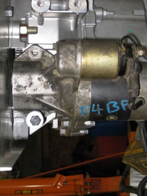
Today has been a very good day! Lots of cutting, grinding and filing and I am very close to calling victory on the tranny mounted F40 starter! I still need to move the starter in another 1/8 to 3/16" for proper teeth mesh, but that will be very simple.
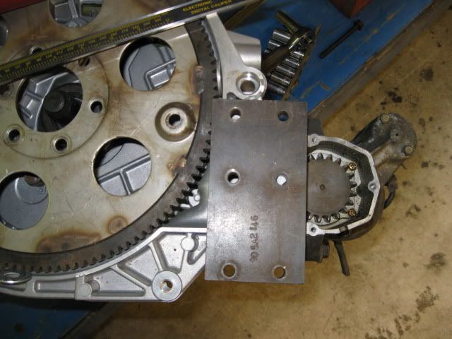
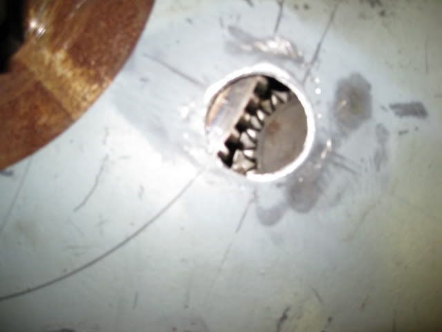
Put the engine/adapter plate and tranny back together with a peek-a-bo hole to monitor the teeth mesh. Here is how close I am so far:
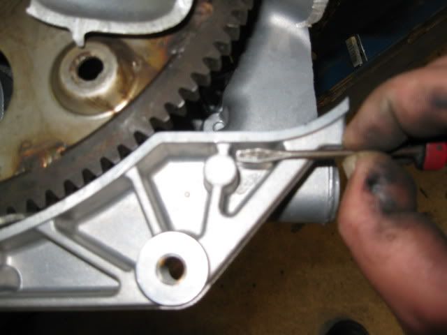
The bolt boss I am using for the starter is only drilled/threaded this deep:
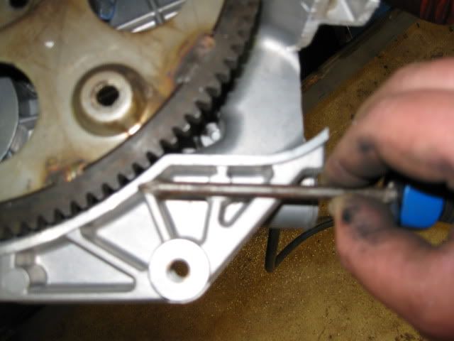
Now it is drilled this deep and tapped:
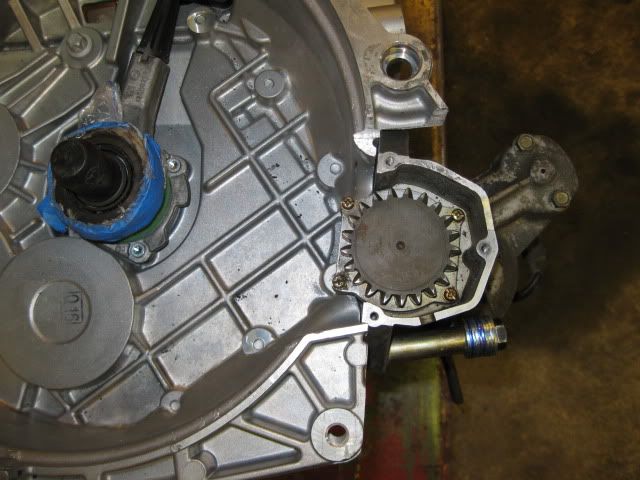
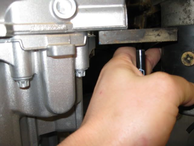
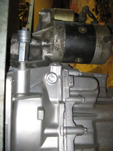
In the picture above, see that lower bolt hole just under the screwdriver, a diagonal cut was made from the right of this bolt hole up to the inner most part of the previous notch. This cut was done all the way through the two lower tranny mount bosses and all the ribbing in this area. In the pic below there the majority of this hole is from the stock starter pocket, but there is a small notch within the bellhousing wall to clear the offset body of the starter.
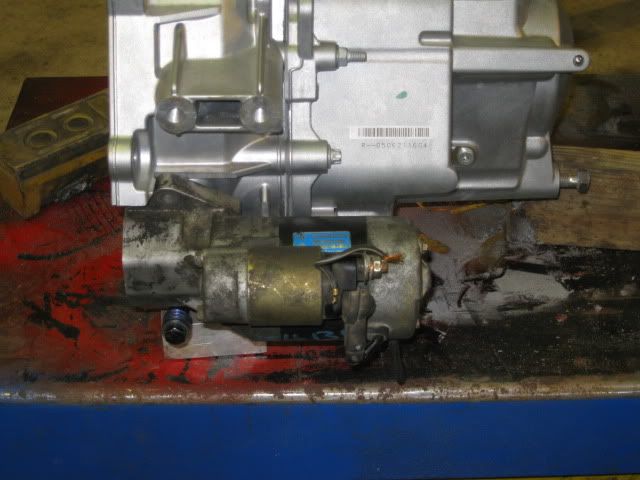
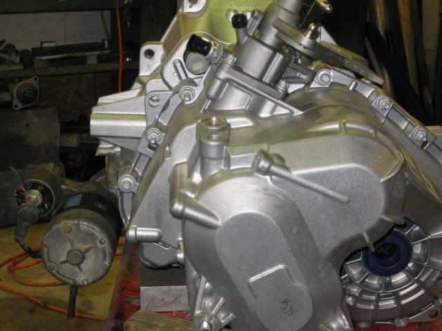
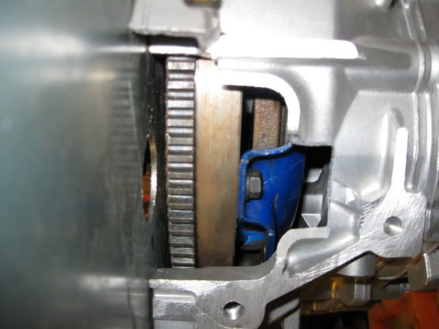
Starter on:
I still need to make the bracket that will come from the upper 2 tranny mount bosses and pickup the upper starter bolt hole (I will probably just tap the starter hole).
Since the lower boss I am using for the lower starter bolt is now at an angle, I slotted the lower hole in the starter and will use an angled washer just under the bolt head.
Depending on free time on Monday, I might finish up the remaining clearance work to get the starter in the final position.
Originally posted by Jefrysuko: You have got some guts there my friend!
No guts, no glory! Actually, worst case I ruin a tranny bellhousing and know 1 method that didn't work... that's the price of R&D sometimes.
The only way to mount a starter to the F40 tranny is to cut material out of your way... I preferred using the stock starter cutout area so the starter is kept low and mostly hidden once installed in the car. It also had the best overall geometry for my starter to fit.
IP: Logged
07:31 AM
whodeanie Member
Posts: 3819 From: woodstock,Ga.,USA Registered: Jan 2008
are you going to make a new cradle with you jig? D.
Yes, that is the plan. I probably will make 2 - the first cradle/adapter/f40 will most likely go into my 4.3 fiero later this year for durability testing and to make sure everything works/fits they way it is supposed to.
IP: Logged
11:37 AM
Isolde Member
Posts: 2504 From: North Logan, Utah, USA Registered: May 2008
Thank you for all the great pics of this, I think they'll be helpful for cutting my F40 to let me mount a starter to a custom bracket to be attached to my LS4. I believe I'll fail my F40 at some point, so I'm not mounting a starter directly to the F40 itself, but I still thank you for the pics.
IP: Logged
12:57 PM
fieroguru Member
Posts: 12128 From: Champaign, IL Registered: Aug 2003
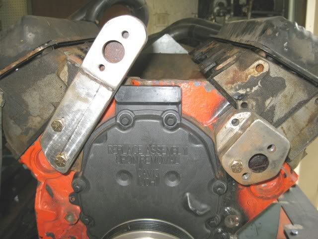
Had a few minutes this weekend to start fabricating the bracket for the top side starter bolt. I did tap the upper starter bolt (M12 x 1.75). I still need to trim the excess material...
looks awesome,have you determined yet what your trans to cradle mount will be like on that side of the engine? you may be able to fab up a combo starter/trans mount bracket without too much trouble. let us know what you come up with
chris
------------------ 88blackchopv8
IP: Logged
12:48 PM
KurtAKX Member
Posts: 4008 From: West Bloomfield, MI Registered: Feb 2002
Had a few minutes this weekend to start fabricating the bracket for the top side starter bolt. I did tap the upper starter bolt (M12 x 1.75). I still need to trim the excess material...
It would be neat if you could add some chevron-shaped ribs or gusseting to that upper bracket. The forces due to the pitch angle of the starter gears will try to push the starter away (increase the center-to-center distance of the axes) making the load on the bracket primarily bending.
Also, it may be worth making the bracket bend angle slightly tighter, so that tightening down the bolts to the bosses preloads the starter pad against the face you machined on the transmission. It should help keep the mesh more consistent under high loads.
[This message has been edited by KurtAKX (edited 07-13-2009).]
IP: Logged
02:23 PM
fieroguru Member
Posts: 12128 From: Champaign, IL Registered: Aug 2003
looks awesome,have you determined yet what your trans to cradle mount will be like on that side of the engine? you may be able to fab up a combo starter/trans mount bracket without too much trouble. let us know what you come up with
chris
On my current SBC setup, there is a solid mount from the tranny in front, but the rear is a triangulated mount coming off the original starter pad on the SBC (no mount attached on the differential side of the tranny).
I am not planning for any of the poly mounts to be attached to the tranny with this install. Both front and rear tranny side mounts will be incorporated into the adapter plate that will span the distance between the front and rear crossmembers. I plan to weld the round ends from the 88 trailing links into the adapter plate and install poly bushings (used the same ends & poly on my 4.3 swap).
I do not know if I can get it to work yet, but the adapter plate mounts will make it easy to remove the tranny w/o messing with mounts. If I make a removable driver side cradle rail on my tubular cradle, I might just be able to pull the tranny from the side by just removing the driver side suspension... CaliforniaKid has a similar setup on his 88, and it is a good idea when the tranny or clutch could be the weakest link.
The other main reason for this is install flexibility.... I can't leave anything alone for long and like to experiment with engine/tranny combos. With the adapter plate taking care of all the tranny side mounts, I could swap in any other fiero manual tranny at a later date (isuzu, getrag or muncie) w/o reworking any mounting and using stock fiero axles (but would have to flip the starter back to the engine side). Also with the adapter plate being 1/8", it could also be sandwiched between any FWD manual tranny and any engine with the FWD pattern... only the engine side mounting would need reworked... this also would standardize my engine location via the fixed location of the adapter plate.
IP: Logged
08:34 PM
fieroguru Member
Posts: 12128 From: Champaign, IL Registered: Aug 2003
It would be neat if you could add some chevron-shaped ribs or gusseting to that upper bracket. The forces due to the pitch angle of the starter gears will try to push the starter away (increase the center-to-center distance of the axes) making the load on the bracket primarily bending.
Also, it may be worth making the bracket bend angle slightly tighter, so that tightening down the bolts to the bosses preloads the starter pad against the face you machined on the transmission. It should help keep the mesh more consistent under high loads.
I am still pondering the upper starter mount bracket. I was going to use 1/4" aluminum, but could not get my hand brake to bend it (atleast not yet). Right now it is 1/8" (I would have preferred 3/16 but didn't have any in the scrap pile) and would need some type of gusseting, but the two bolt holes have a brace between them, so the gusset could not go the length of the part except at the very ends. The other complication is the bellhousing bolt that currently goes behind it - I really would like to keep it so the tranny can be removed with the starter attached.
I am kicking around having the mount follow the tranny case vs. spanning mid air. I could remove more material from the existing ribs to make room for the plate behind the upper portion of the starter and this would allow a stud to be welded to the plate (and will probably use a stud on the lower bolt hole too)...
While I ponder this upper mount, I am planning to start on the intermediate shaft support bracket and the timing cover/balancer/offset housings.
IP: Logged
08:47 PM
Jul 14th, 2009
Isolde Member
Posts: 2504 From: North Logan, Utah, USA Registered: May 2008
how much cranking compression are you seeing with that RamJet 350, and what elevation are you at? I ask to get some idea of the load the starter is seeing, and that, with the shape of the teeth, will give a good idea of the spreading forces at play here.
IP: Logged
10:49 AM
PFF
System Bot
fieroguru Member
Posts: 12128 From: Champaign, IL Registered: Aug 2003
how much cranking compression are you seeing with that RamJet 350, and what elevation are you at? I ask to get some idea of the load the starter is seeing, and that, with the shape of the teeth, will give a good idea of the spreading forces at play here.
I haven't ever checked the cranking compression... Might just have to check one of the cylinders to see. It is a 10.2:1 overall compression ratio with the stock ZZ4 roller cam.
IP: Logged
11:51 AM
Isolde Member
Posts: 2504 From: North Logan, Utah, USA Registered: May 2008
Say what? The RamJet 350 comes with a true 9.4:1, and the RamJet 350 comes with a marine cam, not the ZZ4 cam.
I do not have a RamJet 350 crate engine, I have a RamJet PFI intake on longblock I had built - 1 piece rear seal, 4 bolt main, roller cam block, bored .060 over, with 10.2:1 flat top pistons, ZZ4 roller cam and vortec head machined for higher lift.
[This message has been edited by fieroguru (edited 07-14-2009).]
IP: Logged
07:02 PM
fieroguru Member
Posts: 12128 From: Champaign, IL Registered: Aug 2003
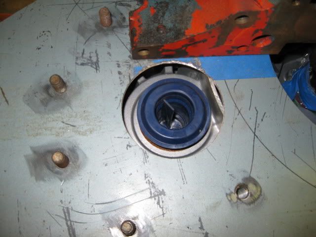
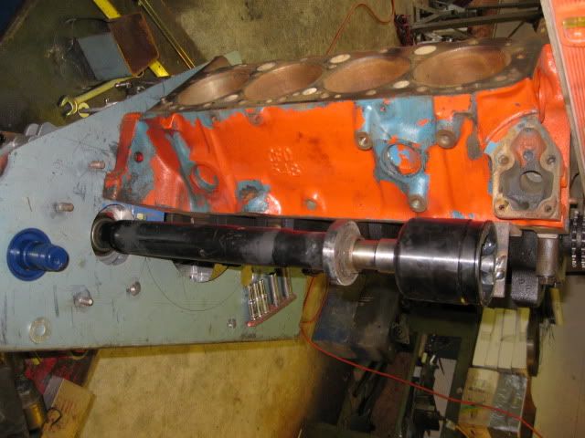
Cut the hole for the intermediate shaft in the adapter plate;
Then I needed a way to properly position the bearing end of the intermetiate shaft so it was properly lined up. Still had the equinox inner tripod on the shelf with no plans for it, so it became the centering device. Drilled a piece of angle for one of the oil pan holes then welded it to the tripod with it tight in the tranny.
Then remove it, install the intermediate shaft and insert the equinox tripod into the end of the shaft and bolt it back in place... now the intermidiate shaft is tight and solid in the proper position for fabricating the bearing support.
The Saab 9-5 intermediate shaft uses a 40mm ID bearing and with my rotated tranny there is roughly 72mm from the engine mount pads and the centerline of the intermediate shaft. I will see what types of off the shelf bearings (pillow block or offset flange type) I can find...
IP: Logged
07:10 PM
Jul 15th, 2009
Isolde Member
Posts: 2504 From: North Logan, Utah, USA Registered: May 2008
Most of the last week was doing "honey do" stuff... refinishing a couple of pieces of furniture... I really do not like messing with wood.
Anyway, I finished up around 4pm today and wanted to do some clearnace checking on a couple of areas of potential issues.
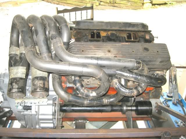
First was the header clearance. They were mocked up with a Getrag (before I went F40) and I figured some rework would be in order to. While I was able to put the collectors in the same location as the getrag, the front bank of tubes will interfere with proper shift function so I will have to redo the position of the collectors slightly. The general design and tube path will remain the same and I will probably make a heat shield on the bottom side of the tubes and collectors to keep the temps down on the tranny itself.
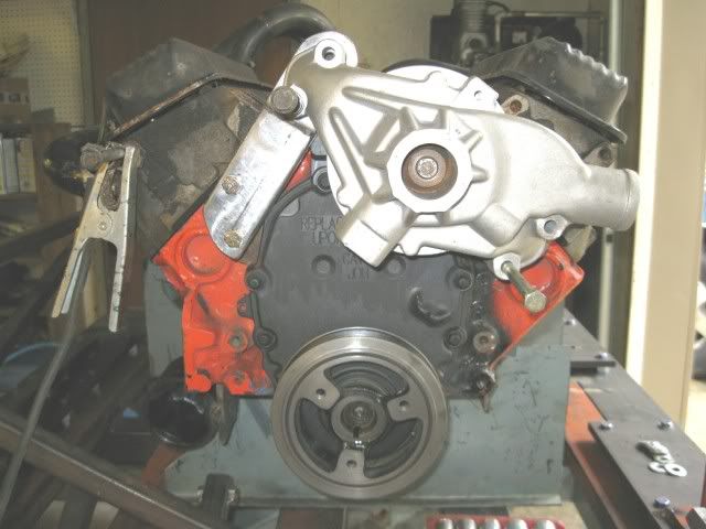
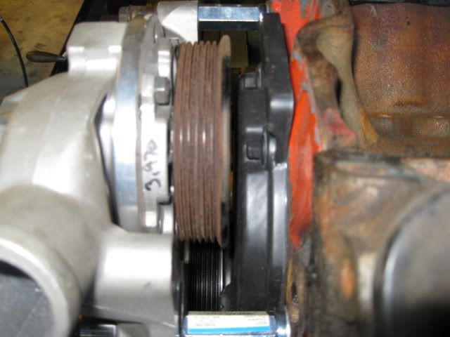
Next was the crank sensor to the 3.1 balancer. Long term I want to run OBDII with the LS1 ecm and to do this requires using the plastic L31 timing cover with crank sensor. Clearance between the sensor and the backside of the balancer will be a limiting factor. Right now the back side of the balancer is 1 3/8" from the face of the block and the outer edge is 2 1/2" from the engine face. The balancer is very close to the sensor boss on the timing cover and I "might" be able to gain some additional clearance once I have a sensor in hand to see if I can modifiy the boss or sensor slightly w/o impacting function. This sensor will be the limiting factor...
On my 4.3 swap the leading edge of the balancer is 2 1/4" from the engine face and the Archie balancer on my SBC car is even closer... I am gaining about 7/8" with my adapter plate design, so I can afford to give up some clearance on the passenger side, but right now I am giving back about 3/4" at the balancer due to the crank sensor and I would really like about 1/4" back (for more room between the driver frame rail and the F40 - which is also super tight).
The other reason I want it to be tighter to the engine is for the offset housings. To make room for the belt drive on the backside of the waterpump, there must be spacers between the engine and the waterpump. With the balancer in its current position the spacers would need to be 2 3/32" and I would really like them to be 2" for ease of fabrication (the current ones on the SBC car are 1 3/4"). Here is how I figured out that measurement:
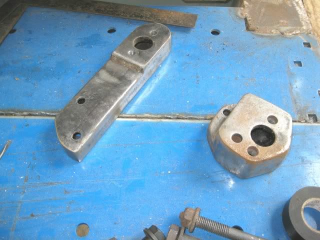
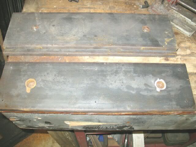
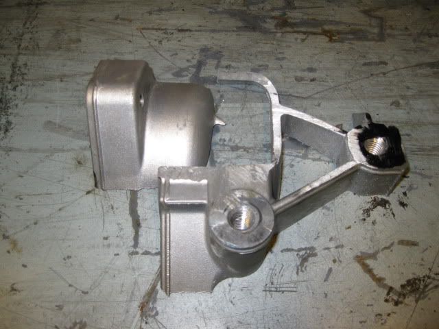
I can be quite the pack rat some times... these were the prototypes for my offset housings on my SBC car (pump position was not right and it hit the wheel well - so I made them again). Each took about 8 hrs of metal fabrication... so I didn't want to throw them away:
I doubt these will be usable this time either. With the thinner adapter plate, the engine will be moving to the driver side about 1/2" and the pump should protrude 1/4" further to the passenger side (net gain of 1/4"). With the contour of the wheel well this 1/4" could provide significant clearance, but I am also lowering the engine at the same time and that might put the pump back into the wheel well (sure a hammer could easily dent the wheel well and make room for the waterpump... but that is just not my style)
[This message has been edited by fieroguru (edited 07-19-2009).]
IP: Logged
08:15 PM
Isolde Member
Posts: 2504 From: North Logan, Utah, USA Registered: May 2008
All that careful labor, just for an obsolete, dinosaur V8. I'm eager for the day you see the light and start on an LS3
Yup! SBC... the new sleeper engine. This will probably be the last SBC upgrade I do for my blue car and then I will build something from the LS series. Most likely what will happen is the engine/tranny/adapter/cradle/headers/harness/ecm will be pulled and offered up for sale (and installed if they wish) once the dyno and 1/4 mile times are known and I get tired of it.
IP: Logged
09:06 PM
Jul 20th, 2009
fieroguru Member
Posts: 12128 From: Champaign, IL Registered: Aug 2003
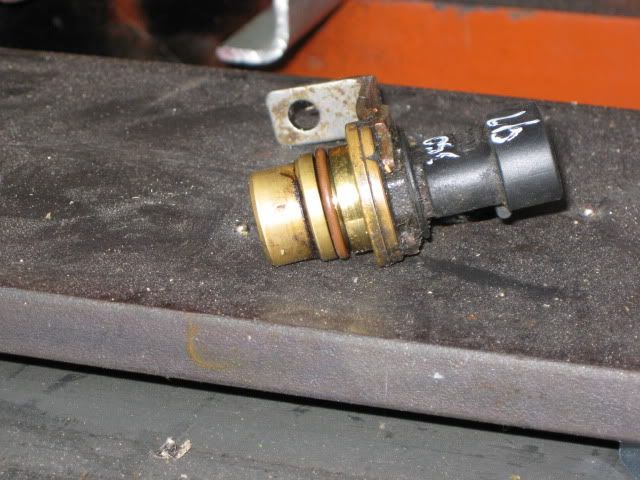
Picked up a crank position sensor and bracket at the junkyard over lunch today (am I the only one who walks the junk yard in kackis?).
The bracket and sensor outer lip will be right in the way of the backside of the balancer:
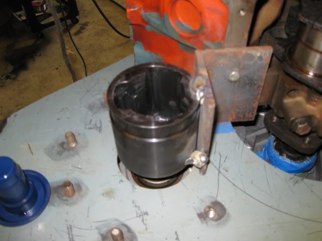
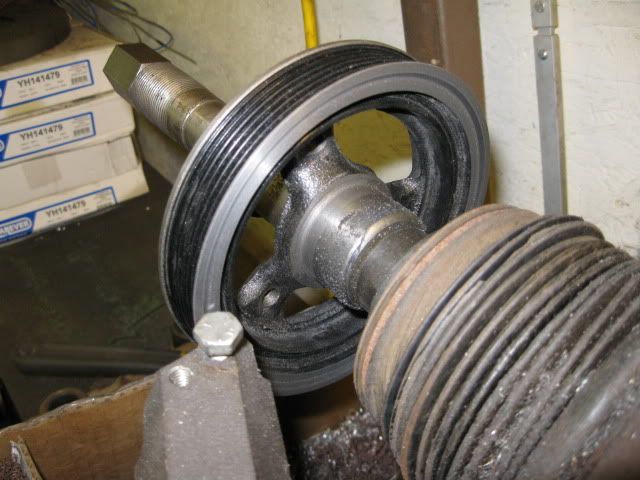
So out came the grinder and the offending edge of the sensor and bracket flange was ground down flush with the round body. Then the balancer was put on the lathe and the back face turned down with a recessed pocket for the timing cover boss:
The waterpump was mocked up again with 2" between the pump and the block.
Then the balancer put back on... and I am within less than 1/32 of being lined up with the waterpump with 2" spacers (close to 3/16" closer than I was yesterday). A little more work on Tuesday and the balancer position sould be finalized.


 thats what welders were made for