Pennock's Fiero Forum
  Technical Discussion & Questions - Archive
  Electrical Wizards of the forum!!! RE: the charging system --- fat question

T H I S   I S   A N   A R C H I V E D   T O P I C
  

Email This Page to Someone! | Printable Version


Electrical Wizards of the forum!!! RE: the charging system --- fat question by unboundmo
Started on: 09-07-2009 03:37 AM
Replies: 14
Last post by: unboundmo on 09-08-2009 09:45 PM
unboundmo
Member
Posts: 2242
From: California
Registered: Sep 2006


Feedback score: N/A
Leave feedback

Rate this member

Report this Post09-07-2009 03:37 AM Click Here to See the Profile for unboundmoSend a Private Message to unboundmoDirect Link to This Post
I can't figure it out! -----------1988 GT Manual

The alternator is still not charging... This is #4. I've bought 1 from Autozone, 2 from pepboys, and 1 now from Napa. I haven't tested the napa one with the machine at the store yet but all others have failed on the machine when I brought them back. All CS re-manufactured.


But then get this.... I go through the trouble shooting steps in the big original 88 shop book.. and somethings are different.

When the car is not running and the key is in the on position I have no volt light but the gauge works and reads correctly. When I actually drive the car, I have an occasional flicker volt light (so I know it works) but there is an also serge. Example: say the gauge is on 12v during the ride but then jumps to 14V-16V usually before shifting and from a starting position then the gauge returns to the 12V....

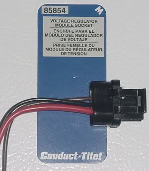
Still with the car key in the ON position... the connector below has three wires. ( red +positive , black -negative , brown -negative ). The negative wires only read 0.03V when tested with the volt meter. the red wire read 12Vs.

When the key is in the OFF position they all read what the battery reads... say 12Vs on every wire. I'm thinking when the car ignition is ON, car running or not, the alternator doesn't see a ground and therefore not charging the battery. Or maybe somewhere around the Ignition??

The big 8 gauge wire that is on the "L" terminal of the alternator has a consistent 12V Positive reading with the car running or not.


How would I go about finding and fixing this problem. Is there a in-fuse or resistor under the dash that's malfunctioning when the ignition is on?

I was thinking of splicing into the brown and black wires at the alternator and just grounding it to the frame. A constant ground with no resistors or fuses and the alt charges the battery..... Will that work instead of the headache?

This charging problem is even affecting my temperature gauge. My cool temp fan sensor will go on , 175 degrees or so and the gauge reads only 100. It will decrease the more I drive on the battery that's not being charged. I don't want the computer to compensate either and hurt the motor...

When I have a fully charged battery --- the temperature gauge is correct.

ANY HELP WOULD BE GREAT... I think I got it all down but if I missed something or confused you, just ask.

Basically all seem to be connected in some way or another. But when the car is ON, I don't read any ground to the alt through the connector... Oh, by the way.. The alt's case and mount bolts are NOT grounded. I think it's from the aluminum bracket.


thanks in advanced

[This message has been edited by unboundmo (edited 09-07-2009).]

IP: Logged
PFF
System Bot
bulldog85043
Member
Posts: 403
From: Phoenix, AZ USA
Registered: Jan 2009


Feedback score: (1)
Leave feedback

Rate this member

Report this Post09-07-2009 07:33 AM Click Here to See the Profile for bulldog85043Send a Private Message to bulldog85043Direct Link to This Post
I had an issue with the connections on the plastic flex-board on the back of the gauge pod that was preventing me from getting a voltage light from coming on. Unfortunately, nobody is making these anymore (that I know of) and I had to fix it by getting one from a donor car. Just make sure you are careful moving the components over from the original to the donor.
IP: Logged
FIEROFLYER
Member
Posts: 3974
From:
Registered: Oct 2002


Feedback score:    (13)
Leave feedback


Total ratings: 180
Rate this member

Report this Post09-07-2009 07:50 AM Click Here to See the Profile for FIEROFLYERSend a Private Message to FIEROFLYERDirect Link to This Post
I have on a few cars wired in a dash type bulb using a marker light socket right at the alt to see if there is a problem with the wiring inside the car. Just connect one side to the brown wire and the other side to + 12 volts ignition. If the bulb lights up the alt is no good, if it does not light up and the alt charges the wiring inside the car is bad. Dan
IP: Logged
Cajun
Member
Posts: 1571
From: Youngsville, La., USA
Registered: Dec 2003


Feedback score: (1)
Leave feedback

Rate this member

Report this Post09-07-2009 07:52 AM Click Here to See the Profile for CajunSend a Private Message to CajunDirect Link to This Post
unboundmo

I have sent you and email to your aol address. From my current location I cannot use the PIP function.

Hope the information helps. You did not mention whether or not this was a conversion or original.

Cajun
IP: Logged
TopNotch
Member
Posts: 3537
From: Lawrenceville, GA USA
Registered: Feb 2009


Feedback score:    (7)
Leave feedback


Total ratings: 60
Rate this member

Report this Post09-07-2009 09:03 AM Click Here to See the Profile for TopNotchClick Here to visit TopNotch's HomePageSend a Private Message to TopNotchDirect Link to This Post
Read this.
I thought 88 cars did not have that problem, but I could be wrong.
IP: Logged
88Ironduke
Member
Posts: 955
From: Willingboro, NJ
Registered: Mar 2002


Feedback score: (4)
Leave feedback

Rate this member

Report this Post09-07-2009 09:52 AM Click Here to See the Profile for 88IrondukeSend a Private Message to 88IrondukeDirect Link to This Post
The Ogres cave has a really good write up on alternators.

The 88 alternator is wired using only a total of 2 wires on the plug, the brown and large red wire. The fat red wire with the terminal end/loop is bolted to the charge stud on the back of the unit. The brown receives a charge circuit that also doubles a fail safe to illuminate the light in the event of alt. failure. The light bulb provides necessary resistance in the charge circuit to keep you from frying the field windings with straight 12v. The black on the plug you have from the store will not use the black wire, however do not ground it or any of the wiring to the frame.

The large red wire on the plug is hot all times, key on or off does not matter.
The brown wire comes from the rally cluster or dash cluster depending on which dash you have. It is only hot in run/bulb test/start.

If you are working on something intermittent you can test the alternators function by putting a jumper wire with alligator clip from the large charge stud to the brown wire on the plug. This is easy as you have a spare plug to work with from the store. Once you verify the charge on the battery 12v engine off 14.0v engine running. Don't drive like this you'll eat the alternator.
If you jumper out the charge circuit and it charges correctly you have a problem as stated above, it may be a bad cluster or a bad wire. Don't leave out you ground straps from inspection. A wire can look good externally but be total crap inside. A bad ground wire has caused a lot of grief for cars and checkbooks.

88Ironduke
IP: Logged
Marvin McInnis
Member
Posts: 11599
From: ~ Kansas City, USA
Registered: Apr 2002


Feedback score: N/A
Leave feedback


Total ratings: 227
Rate this member

Report this Post09-07-2009 11:30 AM Click Here to See the Profile for Marvin McInnisClick Here to visit Marvin McInnis's HomePageSend a Private Message to Marvin McInnisDirect Link to This Post
 
quote
Originally posted by unboundmo:

Oh, by the way.. The alt's case and mount bolts are NOT grounded. I think it's from the aluminum bracket.


The alternator case MUST be grounded. Normally this ground is to the engine block through the mounting bracket. There is no ground wire.

The three wires in the harness connector to the alternator (per the 1988 FSM) are used as follows:

S terminal (3mm red wire) -- Voltage sense (based on the wire size, it may also be a backup path for field excitation current)

F/I terminal (0.8mm brown/white wire) -- Ignition switch position sense (hot in run only)

L terminal (0.8mm brown wire) -- "Charge" indicator drive (this is NOT used for field excitation current on
the CS-130)

P terminal (no connection) -- "Pulse/phase" output (12 volt square wave, indicates alternator rpm)


quote
Originally posted by 88Ironduke:

... you can test the alternators function by putting a jumper wire with alligator clip from the large charge stud to the brown wire on the plug.


DO NOT DO THIS ON A CS-130 ALTERNATOR! The CS and SI alternators are different! The regulator in the CS-130 has just a single transistor switch to ground connected to the "L" terminal, and its sole function is to turn the charge indicator light on and off; the switch is closed when the alternator is not charging. If you connect +12 volts directly to the "L" terminal, it will likely kill the regulator as soon as the ignition is switched on.

Note: Even on the SI alternators, you should never connect the "L" terminal directly to +12 volts ... you should always do it through a lamp or a resistor (50 ohms to 500 ohms) to limit current flow into the "L" terminal.

[This message has been edited by Marvin McInnis (edited 09-08-2009).]

IP: Logged
unboundmo
Member
Posts: 2242
From: California
Registered: Sep 2006


Feedback score: N/A
Leave feedback

Rate this member

Report this Post09-07-2009 02:27 PM Click Here to See the Profile for unboundmoSend a Private Message to unboundmoDirect Link to This Post
Thanks guys for all the replies...

To answer one question... This car was always a 3 wire connector plus the 8 gauge red. I didn't upgrade to this model.

I've checked the cave and have done the trouble shooting. That's why I think it's in the ignition side of things... My bulb "does" work in the cluster along with the gauge. It flickers though when it sees a serge of some kind but is NOT on when the key is in the on position. ( Does a resistor or something in the cluster allow this or is it like a fuse: Once broken it's done? ).... It's like the alt turns on and off for a few seconds or so-- kind of flicker. Where would I find a bad connection without ripping all the wires out of the center consul and dash area when I show connection everywhere.... That's where I'm stumped...

What wires under the dash control this during the ignition "ON"? There's so many colors...Where's the switch that allows the current to become hot to the alt?......

SOMETHING UNUSUAL------- My wires on the connector show hot when the key in the ignition is OFF. I read 12V positive from the 8 gauge red and the red wire from the connector.... I read 12V as a ground from the brown and black wires. When the ignition is ON, I don't see any 12V ground from the brown and black wires--I see 0.03V

Could it still be the cluster? I have an open circuit somewhere right? Anyone know where this circuit is? A pin-point.

Where is the resistor in the car that controls the juice that I see on all the drawings? Is it in the cluster? I did check ohm reading on the cluster and all routes on the board are connected and go somewhere as far as I can tell.


Thanks Mike for the email.. I've seen that before and I think it's from the cave... It's helpful but I don't know where to find the break in the wires if the wires show connection. I'll go through it again though to double check everything.

Top notch... maybe I will just change the bulb... it's cheap enough I guess... Thanks

Marvin... I think it uses the connector for the ground... I checked the alt's mounting bolts plus the case and read nothing---- but this was with the connector off. With the connector attached, then it read that was grounded. Thanks the the diagram and heads up. I'm going to print it off.
-------

Could a bulb have a bad connection.... I mean it'll light up bright and then turn off per say. Not like it's a blown bulb, fuse, or any fusible link resistor thing... Maybe a circuit breaker style that after trip, it re-sets itself. "a blinker bulb?" Is the cluster bulb a fuse blinker style bulb? Turn signal style?

Although when I tested the cluster, I took the bulbs out too and did an ohm reading. They were good....

I'm so bummed... I want to drive

IP: Logged
unboundmo
Member
Posts: 2242
From: California
Registered: Sep 2006


Feedback score: N/A
Leave feedback

Rate this member

Report this Post09-07-2009 02:32 PM Click Here to See the Profile for unboundmoSend a Private Message to unboundmoDirect Link to This Post

unboundmo

2242 posts
Member since Sep 2006
The diagram shows a "C500" on the brown wire and the brown/white wire.... Are those the ohm resistors? Anyone know where they are in the car?

I don't think it's the fusible link on the positive wire "red"


I checked all fuses under the dash too. All good

[This message has been edited by unboundmo (edited 09-07-2009).]

IP: Logged
unboundmo
Member
Posts: 2242
From: California
Registered: Sep 2006


Feedback score: N/A
Leave feedback

Rate this member

Report this Post09-07-2009 04:34 PM Click Here to See the Profile for unboundmoSend a Private Message to unboundmoDirect Link to This Post

unboundmo

2242 posts
Member since Sep 2006
I changed all bulbs and still no light...

Get this too. With the key in ON position, I get 12V power to both sides of the "volt" bulb housing but no light behind the instrument cluster.

The oil light bulb reads 9.36V and on the other side is .03V--- light is on


I also switched housings with each other to see if the bulb housing is bad. no luck.... Maybe it is a resistor on the back of the cluster that is malfunctioning?

I would think I should have the same readings for both oil and volt bulbs, right?

[This message has been edited by unboundmo (edited 09-07-2009).]

IP: Logged
unboundmo
Member
Posts: 2242
From: California
Registered: Sep 2006


Feedback score: N/A
Leave feedback

Rate this member

Report this Post09-07-2009 04:38 PM Click Here to See the Profile for unboundmoSend a Private Message to unboundmoDirect Link to This Post

unboundmo

2242 posts
Member since Sep 2006
. duplicate

[This message has been edited by unboundmo (edited 09-07-2009).]

IP: Logged
PFF
System Bot
Formula88
Member
Posts: 53788
From: Raleigh NC
Registered: Jan 2001


Feedback score: (3)
Leave feedback


Total ratings: 554
Rate this member

Report this Post09-07-2009 10:47 PM Click Here to See the Profile for Formula88Send a Private Message to Formula88Direct Link to This Post
 
quote
Originally posted by unboundmo:
Get this too. With the key in ON position, I get 12V power to both sides of the "volt" bulb housing but no light behind the instrument cluster.


That's why the light isn't on. There's no voltage drop across the bulb. There's a switch not closed somewhere in the circuit between the bulb and ground - that's why you can measure 12V on both sides of the bulb. Wherever the break or switch is in the circuit, that's where you'll measure 12V on one side and 0V on the other.

Most of the circuits on the Fiero operate by switching the ground, so you'll go from (+) to the load, through the switch and then to ground. With the switch off, you'll always read 12V on both sides of the load with the other terminal of your voltmeter connected to a common ground.

[This message has been edited by Formula88 (edited 09-07-2009).]

IP: Logged
unboundmo
Member
Posts: 2242
From: California
Registered: Sep 2006


Feedback score: N/A
Leave feedback

Rate this member

Report this Post09-08-2009 01:27 AM Click Here to See the Profile for unboundmoSend a Private Message to unboundmoDirect Link to This Post
Yes, I agree ..... Is the switch in the instrument cluster?


I'm thinkin of just scouting one gauge pod, temp/oil, out and swapping it out..... I think I've done everything else.

[This message has been edited by unboundmo (edited 09-08-2009).]

IP: Logged
Marvin McInnis
Member
Posts: 11599
From: ~ Kansas City, USA
Registered: Apr 2002


Feedback score: N/A
Leave feedback


Total ratings: 227
Rate this member

Report this Post09-08-2009 01:40 PM Click Here to See the Profile for Marvin McInnisClick Here to visit Marvin McInnis's HomePageSend a Private Message to Marvin McInnisDirect Link to This Post
 
quote
Originally posted by unboundmo:

..... Is he switch in the instrument cluster?


The "switch" in question is inside the voltage regulator. From the '88 FSM: "The digital regulator controls the Charge Indicator light with a solid state driver. The driver turns on the light whenever undervoltage, overvoltage or a stopped generator is detected." In this context, "driver" = "switch" to ground.

[This message has been edited by Marvin McInnis (edited 09-08-2009).]

IP: Logged
unboundmo
Member
Posts: 2242
From: California
Registered: Sep 2006


Feedback score: N/A
Leave feedback

Rate this member

Report this Post09-08-2009 09:45 PM Click Here to See the Profile for unboundmoSend a Private Message to unboundmoDirect Link to This Post
So it could be the alternator...... I'm looking into clusters right now. After I get it and install, I'll check the alt again at someplace. The fix is somewhere?
IP: Logged


All times are ET (US)

T H I S   I S   A N   A R C H I V E D   T O P I C
  

Contact Us | Back To Main Page

Advertizing on PFF | Fiero Parts Vendors
PFF Merchandise | Fiero Gallery
Real-Time Chat | Fiero Related Auctions on eBay


Copyright (c) 1999, C. Pennock