Does anyone see a problem with using the Upshift Light for the Cruise Engaged Light? I have an auto and the Upshift Light spot is filled with an opaque blank. If I can find a Cruise light in the junkyard does anyone see why I cannot use the appropriate wire off the digital cruise to power the light? I don't know yet whether the wire off the digital cruise outputs 12v or not yet.
Do the Fiero's with stock cruise have a Cruise light?
IP: Logged
09:23 AM
Dec 8th, 2008
fierosound Member
Posts: 15145 From: Calgary, Canada Registered: Nov 1999
OK - I NOW HAVE A WORKING, fully functional AC Delco electronic cruise control (model AG) using a GM VSS (Vehicle Speed Sensor) buffer/amplifier with the stock Fiero VSS. The cruise didn't work initially because of a couple of wiring errors I made.
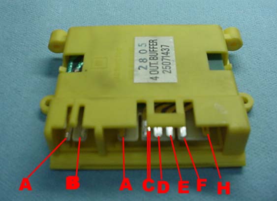
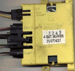
Here's a picture of what the VSS Buffer looks like and what the pinouts are.
When you pull the buffer from the donor car, some will have the VSS wires reversed as below.
You'll have to swap them around in the connector, so that you connect the Fiero's yellow/purple VSS wires to A-yellow B-purple on the buffer. The speedo won't work if they're reversed (Can you guess how I know this?).
You then connect power and ground and the output for cruise. Connect the PIN C output of the VSS Buffer to the electronic cruise control PIN K input. This is where I made my mistake, and why the cruise didn't work initially. I used the 3rd wire down (D) on the VSS Buffer, thinking that was connection C (as in A,B,C), but there was no "B" wire. DOH !!!
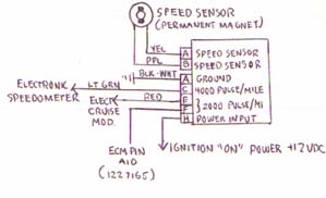
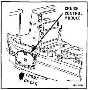
I wired the electronic cruise module in the engine bay as per Darth's wiring diagram here:
I did not use a secondary brake relay, and I grounded both PIN G and PIN H on the module. The rest of the connections to the module are as in Darth's diagram.
Up inside the car, you have to remove the cruise module under the driver's side carpet and make those wiring changes as well.
My 84 does not have this module, as the "module" is built into the 84 speedo. But this makes it even easier, because the bypass connections can be made right at the connector plugging into the bottom of the speedo. Not my car, just showing where the speedo connector is.
Pull the pins from the connector and wire these together as per Fino's diagram to bypass the "module".
Once you make these connections, the signals from the stalk for on/off, resume/accelerate/decelerate will go directly through to the electronic cruise module.
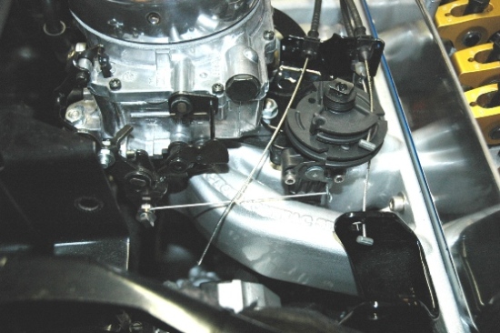
Cruise cables vary between different GM cars, so you should be able to find one of appropriate length that fits your throttle bracket. Most likely you'll have to do some modification to connect the cable to your throttle body/carb/TBI. Once you get the cable connected by whatever modifications are necessary, everything will work exactly as it should.
It sets and holds speed, decelerates/accelerates when holding down the switch - even the automatic tranmission shifts down if necessary. Hitting the brake (I only have an automatic trans) disengages the cruise control as normal.
[This message has been edited by fierosound (edited 10-11-2010).]
IP: Logged
10:05 AM
Fastback 86 Member
Posts: 7849 From: Los Angeles, CA Registered: Sep 2003
1985-89 Firebird / Trans Am / GTA. I also think you might find one in the same year range Grand Ams, Cutlass Calais, etc and other similar body style FWD GM cars; but the Firebird will be your best bet. In the Firebird, it can be found piggy-backing the ECM which is located on the right side of the dash above where the passenger's feet would be. CAMARO DOES NOT USE THIS BOX. 1982-89 Camaros used cable-drive speedos and there was an OPTICAL VSS sensor mounted on the back of the speedometer in these cars. 1990-up Firebirds AND Camaros had the VSS signal processed by the ECM directly.
Well THAT explains it. There were no Firebirds in the yard I was at, I was tearing apart Camaros. Thanks to Fierosound's pictures, I can also tell what size this buffer is, I had thought it was a lot smaller. I'll have to get back to the yards one of these weekends and see if I can't finish this project once and for all.
IP: Logged
10:07 PM
Dec 9th, 2008
fierosound Member
Posts: 15145 From: Calgary, Canada Registered: Nov 1999
...I can also tell what size this buffer is, I had thought it was a lot smaller. I'll have to get back to the yards one of these weekends and see if I can't finish this project once and for all.
From this picture Fino posted earlier, you can see it's about the size of a cigarette package. You'll see them in yellow, white and tan. Color doesn't seem to matter when I tested my extras.
[This message has been edited by fierosound (edited 12-10-2008).]
Does anyone see a problem with using the Upshift Light for the Cruise Engaged Light? I have an auto and the Upshift Light spot is filled with an opaque blank. If I can find a Cruise light in the junkyard does anyone see why I cannot use the appropriate wire off the digital cruise to power the light? I don't know yet whether the wire off the digital cruise outputs 12v or not yet.
Do the Fiero's with stock cruise have a Cruise light?
Stock Fiero's don't have a cruise lamp but the cruise module can drive one. The cruise lamp output goes to ground when active so you want the bulb connected to +12V and the cruise output. I don't see any reason you couldn't use the shift lamp in the cluster, just make sure you cut the wire back to the ECM so they don't argue. The TCC output is the same line as the Shift Lamp but no bulb is installed.
[This message has been edited by TK (edited 12-09-2008).]
IP: Logged
03:44 PM
Dec 10th, 2008
Fastback 86 Member
Posts: 7849 From: Los Angeles, CA Registered: Sep 2003
I've been really looking forward to doing this but I need to know where the module/servo came from. What year range and cars am I looking for. Or a part number, I need some info so when I go to the scrap yard I can find this.
It looks like the PS units rather than AR that had the proper length cable, wire colors matched and TB connection was correct. According to mswenson289.
So I assume I should preferably be looking for a PS?
IP: Logged
10:33 AM
Mar 6th, 2009
fieroluke Member
Posts: 357 From: Erlangen, Germany Registered: Mar 2001
As far as I understood, the PS (as used my mswenson) has the proper cable length for mounting on the firewall, while the AR is good for mounting on the trunk wall. Isn't that so? Are the cable ends different?
I'd like to mount it in the stock location and route the cable like the stock cable, I thought AR was the right one to go for?
Does anybody know what vehicles other than the '97 Cutlass Supreme that was mentioned in this thread have an AR?
I know, many questions, but when I get to the US, I'll have maybe one day for junkyarding, so I have to get the right one on the first try...
Best regards,
Oliver
IP: Logged
03:21 PM
Apr 19th, 2009
jscott1 Member
Posts: 21676 From: Houston, TX , USA Registered: Dec 2001
I'm coming into this thread way late, but now I've got two of the Darth modules to connect.
I can't believe how difficult you guys are making the 4000 ppm scenario... I've been driving my Firebird cluster from the built-in totally 100% stock 4000 ppm output from the 88 speedometer.
All the 86-87 GT clusters also have the 4000 ppm out. The pin N is not active, but if you trace it back to the pin on the chip, the pin right above that you get 4000 ppm. I've been doing this for over 5 years.
Now the question I have is does anyone have a wiring diagram for a car that never had cruise? I'm trying to reverse engineer this, but a simple pinout of what connects to the electronic module would make my life easier.
[This message has been edited by jscott1 (edited 04-20-2009).]
IP: Logged
10:40 PM
fierosound Member
Posts: 15145 From: Calgary, Canada Registered: Nov 1999
I can't believe how difficult you guys are making the 4000 ppm scenario... I've been driving my Firebird cluster from the built-in totally 100% stock 4000 ppm output from the 88 speedometer.
I have an 84 with cruise module IN the speedo. What I've posted also works for any Fiero.
IP: Logged
11:57 PM
Apr 20th, 2009
Darth Fiero Member
Posts: 5921 From: Waterloo, Indiana Registered: Oct 2002
Now the question I have is does anyone have a wiring diagram for a car that never had cruise? I'm trying to reverse engineer this, but a simple pinout of what connects to the electronic module would make my life easier.
I have an 84 with cruise module IN the speedo. What I've posted also works for any Fiero.
Thanks for posting that. But those yellow buffer boxes are getting hard to find. You can get any 86-88 GT cluster and use the buffer out of it. That's how I build my Firebird plug and play harness.
Thanks for the drawing Ryan!
IP: Logged
11:01 AM
Jun 5th, 2009
bnevets27 Member
Posts: 264 From: Ontario, Canada Registered: Oct 2007
Just a heads up. I couldn't get mine working till I took a hard look at the wiring chart and the only way I got it to work was swaping pin D with G. So I think theres is a small error in that chart.
I was also wondering if any one knows or has found that the unit is sensitive to heat?
IP: Logged
12:30 PM
Feb 10th, 2010
Daviero Member
Posts: 381 From: Thunder Bay, ON Canada Registered: Jan 2006
I have my cruise wired up as prescribed in Darth's chart but still have trouble. From Darth's checklist in this post https://www.fiero.nl/forum/Forum2/HTML/102406.html For Pin D: 5) Do you have 12v + voltage coming into pin D any time the key is on except when the brakes are applied and/or when you step on the clutch pedal; and does this signal drop to ground when you apply the brakes and/or step on the clutch pedal? (Test this circuit using a test light hooked to POS battery voltage so you can verify a good ground with brakes applied and/or clutch pedal depressed – test light should light up brightly NOT dim when it comes on)
On mine the 12v + is ok, but the ground is weak. Checking the ground with a bulb - the bulb glows dim and is slow. But the way it is wired with 12V + applied through a light and to Pin D, the only ground available is back through the control coil of the relay right? So the bulb glows dim and is slow. All other checks on the list pan out well, just not the ground of #5. What is there wrong? I have checked 2 separate modules - one coded "V8" off my doner DeVille, and one coded "AR". Both operate the same - when setting the cruise I get a big burst of throttle as I lift my foot off the gas, and then the cruise does not hold. I have the car on stands so I can test the cruise - might the free wheeling/ no load condition have a detrimental effect? There are notes on reversing Pins D and G on this thread. Am I finding the reason why?
------------------ Daviero - 88 N* GT
IP: Logged
08:00 PM
Feb 11th, 2010
winger1955 Member
Posts: 579 From: toledo-ohio-usa Registered: Jan 2008
I have my cruise wired up as prescribed in Darth's chart but still have trouble. From Darth's checklist in this post https://www.fiero.nl/forum/Forum2/HTML/102406.html For Pin D: 5) Do you have 12v + voltage coming into pin D any time the key is on except when the brakes are applied and/or when you step on the clutch pedal; and does this signal drop to ground when you apply the brakes and/or step on the clutch pedal? (Test this circuit using a test light hooked to POS battery voltage so you can verify a good ground with brakes applied and/or clutch pedal depressed – test light should light up brightly NOT dim when it comes on)
On mine the 12v + is ok, but the ground is weak. Checking the ground with a bulb - the bulb glows dim and is slow. But the way it is wired with 12V + applied through a light and to Pin D, the only ground available is back through the control coil of the relay right? So the bulb glows dim and is slow.
You might have this condition if the test light you are using is overpowering the relay control coil. I should have mentioned this in the other post I made.
quote
All other checks on the list pan out well, just not the ground of #5. What is there wrong? I have checked 2 separate modules - one coded "V8" off my doner DeVille, and one coded "AR". Both operate the same - when setting the cruise I get a big burst of throttle as I lift my foot off the gas, and then the cruise does not hold. I have the car on stands so I can test the cruise - might the free wheeling/ no load condition have a detrimental effect?
Sounds normal to me. The cruise is engaging but because there is no load on the drive wheels, the speed is increasing too fast for the cruise module's liking so it is shutting itself down. Do a road test to verify.
quote
There are notes on reversing Pins D and G on this thread. Am I finding the reason why?
DO NOT swap the wiring to pins D and G on the electronic cruise box. If you do this, the cruise will not operate.
-ryan ------------------ 6+ years on this same swap -- NO engine or transmission failures... Custom GM OBD1 & OBD2 Tuning | Engine Conversions & more | www.gmtuners.com
[This message has been edited by Darth Fiero (edited 02-11-2010).]
IP: Logged
02:27 PM
Daviero Member
Posts: 381 From: Thunder Bay, ON Canada Registered: Jan 2006
Originally posted by Darth Fiero: You might have this condition if the test light you are using is overpowering the relay control coil. I should have mentioned this in the other post I made.
This makes sense - testing with an electronic 12v pos / 12V neg tester, it showed a good ground. For the light bulb test I was using was a signal light bulb.
quote
Sounds normal to me. The cruise is engaging but because there is no load on the drive wheels, the speed is increasing too fast for the cruise module's liking so it is shutting itself down. Do a road test to verify.
I wondered if this what the throttle burst actually was - I had tried seting the cruise with the E-brake on hard, but not enough load. While a road test up here in Feb is possible, I think I'll have to wait for snow and salt free roads in about May. :-( My car is a summer queen :-)
quote
DO NOT swap the wiring to pins D and G on the electronic cruise box. If you do this, the cruise will not operate.
Thanks for confirming this Ryan. I was hoping you might respond to my post. Thanks also for making things like the cruise wiring available to us all!
EDIT: The roads were clean and dry of snow so I went for a "cruise" in February and everything worked as prescribed! Thanks again Ryan!!
------------------ Daviero - 88 N* GT
[This message has been edited by Daviero (edited 02-15-2010).]
IP: Logged
09:47 PM
Feb 12th, 2010
bnevets27 Member
Posts: 264 From: Ontario, Canada Registered: Oct 2007
Ryan, I'm a little confused with you stating that pin D and G should not be swapped. Maybe swapped is the wrong way to word it. I have had my cruise installed and working well for a year now. I had trouble with getting it to work at first. So I kept looking over the wiring chart that you have given to see what I had done wrong. With some help it was pointed out that I should "swap" pin D and G. Here's how I came to that conclusion. BTW I was using this chart you have provided: http://www.gmtuners.com/fil...ise_elect_cruise.pdf
According to the descriptions:
TCC Brake Input N.C ---------- Brake Switch (hot with key on and brakes not applied; 0 volts when brakes applied) Brake Lamp Input N.O--------- Terminal "30" of the relay
Relay Switched common - 30 ------------ Terminal G of the cruise control module
From my understanding, when the key is on and brakes not applied 12v is being sent from term 30 of the relay. When the brake are applied then term 30 of the relay is ground.
So looking at the descriptions it would makes sense for term 30 of the relay to be wired to TCC Brake Input N.C. It meets the conditions in the description. It then also make sense that Brake Lamp Input N.O be wired to the Brake switch, considering it's asking for a brake lamp input which is the brake switch.
Once I had my cruise wired up like that its been working great. I'm just wondering why I had to wire mine this way. Maybe I'm the only one??
I appreciate you giving us the ability to add this to our cars.
IP: Logged
03:23 AM
Feb 13th, 2010
Darth Fiero Member
Posts: 5921 From: Waterloo, Indiana Registered: Oct 2002
Ryan, I'm a little confused with you stating that pin D and G should not be swapped. Maybe swapped is the wrong way to word it. I have had my cruise installed and working well for a year now. I had trouble with getting it to work at first. So I kept looking over the wiring chart that you have given to see what I had done wrong. With some help it was pointed out that I should "swap" pin D and G. Here's how I came to that conclusion. BTW I was using this chart you have provided: http://www.gmtuners.com/fil...ise_elect_cruise.pdf
According to the descriptions:
TCC Brake Input N.C ---------- Brake Switch (hot with key on and brakes not applied; 0 volts when brakes applied) Brake Lamp Input N.O--------- Terminal "30" of the relay
Relay Switched common - 30 ------------ Terminal G of the cruise control module
From my understanding, when the key is on and brakes not applied 12v is being sent from term 30 of the relay. When the brake are applied then term 30 of the relay is ground.
So looking at the descriptions it would makes sense for term 30 of the relay to be wired to TCC Brake Input N.C. It meets the conditions in the description. It then also make sense that Brake Lamp Input N.O be wired to the Brake switch, considering it's asking for a brake lamp input which is the brake switch.
Once I had my cruise wired up like that its been working great. I'm just wondering why I had to wire mine this way. Maybe I'm the only one??
I appreciate you giving us the ability to add this to our cars.
Pin D connects directly to the purple wire that originally went to that little vacuum solenoid attached to the bracket the factory Fiero cruise servo was bolted to. This wire is connected to the cruise brake switch (and clutch switch, if you have a manual trans) which are both a N.C. (normally closed) to 12v ign + power; and this circuit opens (loses 12v +) when you step on the brakes (and/or the clutch pedal in the case of a manual trans car).
Pin G needs to see a N.O. (normally open - not seeing 12v + power) circuit when the brake pedal is NOT pressed. Then when you press the brake pedal, it should see 12v + voltage.
I have run into quite a few of these cruise modules that seem to be sensitive to what comes into the D and G pins concerning power and ground. Pin D wants to see a good ground signal with the brake pedal pressed, and a good 12v + signal with the key on and the brake not pressed. Pin G is the opposite (needs to see good ground with brake not pressed and 12v+ with brake pressed). I have found that if either of these circuits do not see good ground signals when they are expected, the cruise won't work. If you wire up this cruise module using my Relay Method (#2), the relay will provide a ground signal for pin D (thru the relay coil when it is deactivated) and the switching of the relay will provide a good ground signal to Pin G when expected.
Furthermore, this cruise module needs to see both of these signals change state (basically it wants to see both brake switches work at least once) per drive cycle before it will enable the cruise control to work.


.jpg)