the cruise control module I bought has an AR on the label. it is from a chevy with a 3.1 engine. Should I also get the throttle cable for hook-up to a stock fiero ? Is the length and connection to the throttle body the same as the stock fiero cable ?
I saw another car in the yard with a cruise control module that looked the same but had AG on the label intsead of AR. What's the difference in the module ?
Mine is an "AR" as shown in the photos above. The difference that I know of is either a V6 or V8 car the V6 will work. I don't know what codes go to what but mine was a 1997 Cutlass Supreme V6. The cable I did not post photos I can post some if you want.
Ed
IP: Logged
06:39 AM
PaulJK Member
Posts: 6638 From: Los Angeles Registered: Oct 2001
I was thinking that using the fiero cable, but modifying the end to attach to the digital cruise control module was the way to go.
You used the digital cruise control cable form the donor with no trouble hooking it to the stock fiero throttle body ? The length and attaching was OK ? If so, I can go get the cable today and save myself experimenting with the end of the fiero cable. I picked up the digital EGR yesterday.
[This message has been edited by PaulJK (edited 04-01-2008).]
IP: Logged
06:59 AM
Fino Member
Posts: 812 From: St. Johns, MI. USA Registered: Jan 2002
I was thinking that using the fiero cable, but modifying the end to attach to the digital cruise control module was the way to go.
You used the digital cruise control cable form the donor with no trouble hooking it to the stock fiero throttle body ? The length and attaching was OK ? If so, I can go get the cable today and save myself experimenting with the end of the fiero cable.
No, the new cable method needs a lot of modifing to the bracket and an adapter needs to be made for the new cable to work on the TB. You might want to do it your way it might be easer than mine. Maybe you could post some photos of yours while you make it for the rest of us.
Ed
IP: Logged
07:12 AM
Fino Member
Posts: 812 From: St. Johns, MI. USA Registered: Jan 2002
i'm pretty sure i will. it will be more expensive than just getting the speedo interface but probably worth it. right now i'm still getting the parts together and will look for the ECU later today.
actually i did not Really have to do any of this - my stock cruise control works perfectly . if i can find a turbo set-up at a good price, i'll throw that in with this project too.
[This message has been edited by PaulJK (edited 04-01-2008).]
IP: Logged
07:54 AM
Fino Member
Posts: 812 From: St. Johns, MI. USA Registered: Jan 2002
i'm pretty sure. it will be more expensive than just getting the speedo interface but probably worth it. right now i'm still getting the parts together and will look for the ECU later today.
actually i did not Really have to do any of this - my stock cruise control works perfectly
I have already started and there is no turning back now. If I had to do it all over I might not have done this. I am still surching for parts to make this work.
Ed
IP: Logged
07:58 AM
PaulJK Member
Posts: 6638 From: Los Angeles Registered: Oct 2001
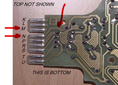
I made a mistake in my previous post/pic. The terminal in question is terminal "N" not terminal "M". On the GT 120mph speedo, it looks like nothing connects to term N from the factory. This may very well be a 4k ppm output signal circuit.
For those of you who have earlier speedos or speedos with no connection to Term "N", see if you can post up a pic of the circuit board (both sides if possible) so we can examine it and determine if a 4k ppm signal output can be added to those.
-ryan
IP: Logged
03:46 PM
Fino Member
Posts: 812 From: St. Johns, MI. USA Registered: Jan 2002
It looks good. Now we need to get someone to test it.
This is a photo of the circuit
This is the same photo but you can see where terminal "U" and "N" go. The chip they go into is the same I would think it might be the converter chip for the VSS..
This is the chip they go into. Top left pin is "U" & next to it is "N".
Now the test. Will someone take a test light (I am NOT going to go into all the safety about driving while checking) and test while the wheels are going around terminal "U" & "N"? You hopefully will see that terminal "U" will flash slower than terminal "N". Let us know.
Archie said: Note that GM told it's service techs back in 86 or 87 that they souldn't rotate the left rear axle when the suspension was unloaded because it wout the inboard Tri=Pot at an angle that was not within the recommended drive angle for the axles. In other words, it would bind.
Thank you Ed
BTW Ryan Yes I knew last night about the "M" but it was late and immaterial to the topic so I thought I wouldn't harass you. But your fair game today. If I had my chip I could test it myself
[This message has been edited by Fino (edited 04-01-2008).]
IP: Logged
04:42 PM
Fino Member
Posts: 812 From: St. Johns, MI. USA Registered: Jan 2002
I made a mistake in my previous post/pic. The terminal in question is terminal "N" not terminal "M". On the GT 120mph speedo, it looks like nothing connects to term N from the factory. This may very well be a 4k ppm output signal circuit.
For those of you who have earlier speedos or speedos with no connection to Term "N", see if you can post up a pic of the circuit board (both sides if possible) so we can examine it and determine if a 4k ppm signal output can be added to those.
-ryan
This is a 85 mph PCB
Other side.
When I get my car running again I will check to see if I can find a 4K signal some where.
Ed
IP: Logged
10:56 PM
Apr 2nd, 2008
Darth Fiero Member
Posts: 5921 From: Waterloo, Indiana Registered: Oct 2002
I wouldn't try using a test light on this circuit, it could overload it. Instead, use a digital volt meter. One test lead connected to 12v + and the other to "terminal N". Should see voltage fluctuate indicating pulses, but unless your DVOM can display Hz, you will have no way of knowing if this is a true 4k ppm signal or not. I think the best thing to do would be to just hook this up to the VSS input for the digital cruise module and see if it allows it to work normally.
IP: Logged
02:25 AM
PFF
System Bot
PaulJK Member
Posts: 6638 From: Los Angeles Registered: Oct 2001
I wouldn't try using a test light on this circuit, it could overload it. Instead, use a digital volt meter. One test lead connected to 12v + and the other to "terminal N". Should see voltage fluctuate indicating pulses, but unless your DVOM can display Hz, you will have no way of knowing if this is a true 4k ppm signal or not. I think the best thing to do would be to just hook this up to the VSS input for the digital cruise module and see if it allows it to work normally.
Yes, but that is why I originally said:
"One of those four holes is the 4K signal and if you have an oscilloscope or just a COMPUTER SAFE test light the wire could be found by testing each wire while you turn the wheels, the one that blinks on and off will be the 4K signal."
but I got tired of repeating it so I just shortened it up because I was tired.
I have a cruise control setup out of a 1997 GTP (The parts car I got my engine from), and was wondering what the advantage to changing over to it is, as opposed to just using the stock fiero setup? Sorry if this seems like I am hijacking the thread.
Dan
IP: Logged
09:24 AM
fierosound Member
Posts: 15145 From: Calgary, Canada Registered: Nov 1999
I have a cruise control setup out of a 1997 GTP (The parts car I got my engine from), and was wondering what the advantage to changing over to it is, as opposed to just using the stock fiero setup?
It takes up a lot less room in the engine bay. The electronic cruise module eliminates the need for the vacuum can, servo and related vacuum hoses. I believe in your case your new engine's ECM provides the correct 4000ppm output for the cruise module.
But at present, it seems nobody can get it working with a stock Fiero VSS even with the buffer. It seems there's at least a half dozen of us with these electronic cruise controls installed (following KlingonFiero's writeup) trying to figure out why we can't get them to work. So until someone can shed light on an EXACT parts list (which module, which buffer) and installation and wiring procedure that WORKS, I'd advise anyone else to hold off until we get this figured out.
------------------ 3.4L S/C 87 GT www.fierosound.com 2002/2003/2004 World of Wheels Winner & Multiple IASCA Stereo Award Winner
[This message has been edited by fierosound (edited 04-02-2008).]
IP: Logged
11:08 AM
Fastback 86 Member
Posts: 7849 From: Los Angeles, CA Registered: Sep 2003
Well, maybe I'll be hitting the junkyard looking for one of those 80's car piggyback buffers. I'd rather not mess with the speedo circut board since I don't know a lot about electronics. All I have left to do is make a bracket to hold the cruise control cable in place (I modified the Fiero cable) and hook this 4k ppm wire to something. I've already hacked up the wiring in the engine bay and at the cruise box, and I'd like to keep it isolated to those areas.
IP: Logged
12:43 PM
mswenson289 Member
Posts: 195 From: Cleveland, MO. USA Registered: Dec 2007
Fastback86 Would you mind sharing pictures of the cable you modified, or a detailed discription? Short of adding the bracket from the orginal I have not found a way to attach the throttle cable. Mike
IP: Logged
01:05 PM
Fino Member
Posts: 812 From: St. Johns, MI. USA Registered: Jan 2002
This is how I did mine. I used the cable that came with the digital cruise and made an adaptor to fit on the stock bracket and bolted it down. I will cut it off and weld this later.
Other side
Top
I connected it to the TB using a bracket to adapt to the cable.
Close-up
Screw lock
Other side I do not have mine done yet I am still working on it. Ed
[This message has been edited by Fino (edited 04-02-2008).]
IP: Logged
01:25 PM
mswenson289 Member
Posts: 195 From: Cleveland, MO. USA Registered: Dec 2007
Cool, I found a unit marked PS rather than AR that had the proper legnth cable, wire colors matched and TB connection was correct. So the bracket is of the most consern at this time.
IP: Logged
03:55 PM
CC Rider Member
Posts: 2037 From: Cameron Park, Ca Registered: May 2001
Well, maybe I'll be hitting the junkyard looking for one of those 80's car piggyback buffers. I'd rather not mess with the speedo circut board since I don't know a lot about electronics.
I picked up a "yellow box" buffer from a Cadillac Cimmaron yesterday for $10.50; that means it's probably $5 or less anywhere else.
IP: Logged
09:38 PM
Apr 3rd, 2008
Fastback 86 Member
Posts: 7849 From: Los Angeles, CA Registered: Sep 2003
Fastback86 Would you mind sharing pictures of the cable you modified, or a detailed discription? Short of adding the bracket from the orginal I have not found a way to attach the throttle cable. Mike
I'll try to describe it since I don't have any pictures right now.
First, if you remove the cable from the electric cruise unit, you'll see that the actual metal cable inside the plastic sheath has a little nut on the end of it that hooks onto a plastic strap coming out of the electric cruise unit. I presume that the plastic strap is wound around a drum inside the electric cruise unit and attached to a servo. Thus, when the plastic strap is reeled in, it pulls on the cable and in turn pulls the throttle open.
Now, on the throttle body end of the cable that comes with the electric cruise unit, the connector is much different than the one used on the Fiero. I found no way to make the Fiero throttle body and the electric cruise cable work together, so I ditched the electric cruise cable.
On the stock Fiero cruise cable on the servo end, there is a yellow plastic piece with a metal pin on the end of it that hooks on to the cruise control servo. If you turn that yellow piece around, you'll see that the metal cable comes into through the middle of the plastic piece and is kept from slipping out by a little metal nut just like the electric cruise control cable.
So, what I did was destroy the yellow plastic piece on the stock Fiero cruise control cable to expose the metal cable itself with the nut on the end. That nut on the end fits perfectly into the hook on the plastic strap on the electric cruise control module. Voila, you have connected the two together.
Now, to protect the connection from the elements, I went back to the electric cruise control cable to the module end and broke off the plastic cone on the end of the cable that plugs into the module. I ran the Fiero cruise cable through the cone and connected the cable to the servo, then plugged the cone back into the module so that the whole connection is inside the cone and protected.
The only problem I'm left with is that the cable is not held in place by anything other than the module and the throttle body. The problem here is that if I were to activate the cruise, the module would start tugging on the cable and instead of opening the throttle body, the throttle body would be held closed by its spring and the module would just start pulling the whole cable towards itself. To remedy this, I'm going to modify the stock Fiero bracket that held the cable in place so that it will fit around the electric cruise module (which I have mounted right where the stock vacuum module used to be) to hold the cable in place. All I need is to borrow a saw to cut up the bracket.
Then, I connect that 4k ppm wire and hopefully, I have electric cruise.
IP: Logged
03:53 AM
PaulJK Member
Posts: 6638 From: Los Angeles Registered: Oct 2001
... where on the car did you find the yellow box? Just trying to save myself some time searching for it.
Driver's footwell by the fusebox. Also found 1 in a firebird (1990-ish?) under the dash by the glovebox.
quote
Originally posted by Fastback 86:
.... it will probably be a while before I get a chance to finish this project.
If your speedo buffer has circuits connected to the N or M tabs, you might already have a 4000 ppm signal. In this photo, N has a circuit but M does not. Just splice into the wire in the connector for the tab. It would be nice if Fierosound elaborates a little on the experience with buffers. Looks like Carl did it with whatever an LQ1 swap is - too bad he didn't say if he was using a stock fiero trans or what he used for the 4000 ppm signal output.
You might be able to get some plastic cable tie anchors from Radio Shack to secure the outside of the cable temporarily to test it. The tie anchors look like this and would probably hold the outside of the cable long enough for a test. The exhaust heat would probably melt them loose long term but you could see if your wiring was done correctly.
quote
Originally posted by Fastback 86:
Let me know if it works for you, it will probably be a while before I get a chance to finish this project.
I'm still getting parts together, but i might end up just selling them all as a package deal. I'm not tearing into my car until i have ALL the parts and ALL the info. My stock cruise control is working fine. Same with the ECM project ....
[This message has been edited by PaulJK (edited 04-04-2008).]
IP: Logged
06:13 AM
fierosound Member
Posts: 15145 From: Calgary, Canada Registered: Nov 1999
Does this mean the "yellow box" buffer won't work either ?
My friend has just gone through this for the past 2 weeks - he's retired and has more time to screw around with this than me. He tried this install based on what he saw on my car and KlingonFiero's writeup and Darth's wiring diagrams as well. But he did the smart thing and did temporary connections on everything so everything would be easily reversible.
The white buffer seems to be in cars that used a 2000ppm VSS like the 92 Caprice. We found a yellow buffer in an 87 Firebird V6 which uses a 4000ppm VSS according to all we could find http://www.the12volt.com/in...uisedetail/1858.html On the Firebird, they are located behind the dash on the passenger side, piggybacked onto the ECM bracket.
He's tried both the white and yellow buffers. As noted, the speedo will stop working when the purple/yellow buffer wires are connected to the VSS wiring, but reversing them in the buffer connection gets the speedo working again - but it's likely backward to what the buffer wants so it doesn't output a signal to the cruise.
So, he unplugged the speedo with the wires to the buffer switched back as it was. This should result in basically a direct connection between the VSS and the buffer. That didn't seem to make any difference either. We also found a smaller buffer from an 88 Olds Delta 88, and that car also uses a 4000ppm VSS according to the data at 12volt.com . He tried that buffer any number of ways with no success.
He's looked at the M and N terminals on the speedo (86 SE) and connecting to there resulted in no response from the cruise. He next figured he could tap a 4000ppm signal from the speedo's buffer as that feeds the speedo/odometer - but it's connected with a ribbon cable with no easy way to solder on a wire to tap it. He was worried about cooking his speedo.
By the way, he's no "dummy" as he's swapped in a 3400 aluminum head engine, built a turbo unit for it, installed power steering and automatically leveling rear air suspension on his 86 SE. So I doubt he got something wired wrong.
He GAVE UP yesterday and reinstalled all his original vacuum cruise equipment.
We cannot figure out why our units do not function. And it appears there's at least a half dozen of us here on PFF with the same problem, not counting the guys doing the install in a car that isn't even driveable for testing.
It seems KlingonFiero has the only working setup on a "stock" Fiero using a buffer wired to the Fiero's 4000ppm VSS.
[This message has been edited by fierosound (edited 04-03-2008).]
IP: Logged
10:11 AM
fierosound Member
Posts: 15145 From: Calgary, Canada Registered: Nov 1999
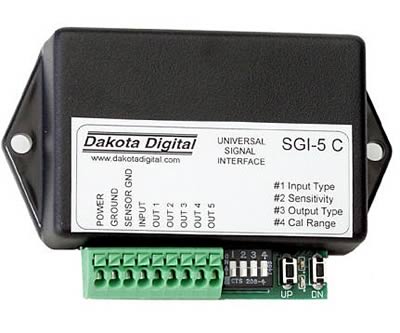
I'm thinking that either of these interfaces might do the trick ...
Dakota Digital $80
Dakota Digital universal signal interface http://www.dakotadigital.com/pdf/sgi-5c.pdf May work. Application 2 - converts input of VSS 4000ppm A/C sinewave to 4000ppm O/C squarewave (Output 4) to cruise control module. But that is what the GM buffers we've been testing should do as well. I'd buy a Dakota interface in a minute if someone KNOWS it definitely works.
IP: Logged
11:54 AM
Fino Member
Posts: 812 From: St. Johns, MI. USA Registered: Jan 2002
Dakota Digital universal signal interface http://www.dakotadigital.com/pdf/sgi-5c.pdf May work. Application 2 - converts input of VSS 4000ppm A/C sinewave to 4000ppm O/C squarewave (Output 4) to cruise control module. But that is what the GM buffers we've been testing should do as well. I'd buy a Dakota interface in a minute if someone KNOWS it definitely works.
From what they say I don't think it will work We need a 4000 (sine wave A/C) to a 4000 (Square wave D/C).
None of these say that. ---------------------------------------------------- 1. Recalibrate a high speed (64,000ppm � 250,000ppm) signal for an OEM speedometer. Do not use this unit to adjust a signal going to an anti-lock braking system. 2. Recalibrate a low speed (8000ppm � 4000ppm) signal for an OEM or aftermarket speedometer or fuel injection computer. 3. Convert a high-speed signal found on newer GM transmissions down to a low speed signal to run a speedometer, cruise control, or fuel injection computer. 4. Convert an 8000ppm signal from an aftermarket signal generator to a 4000ppm or 2000ppm to run an OEM cruise control or fuel injection computer. 5. Convert a 16000ppm signal from a VDO Hall Effect signal generator to an 8000ppm, 4000ppm, or 2000ppm to run a cruise control or fuel injection computer. 6. Convert a 4000ppm signal from an OEM transmission speed sensor or ECM output to an 8000ppm signal for an aftermarket speedometer. --------------------------------------------------------------- I do think the buffer I talked about should work. If someone has one could you remove the PCB and take a photo so I can see the circuit.
The problem with crossing the wires to the speed buffer is: 1 The yellow wire in a STOCK Fiero goes to the speedo circuit. 2 The PPL wire goes to GROUND in the speedo.
You can't cross these wires or you will take the yellow wire to ground. Now comes the question inside the buffer box does the PPL wire go to ground?
The thing that worries me is someone has tried this and it did not work. I would not connect the PPL wire to the buffer only the yel then the rest. But, I need to see the PCB. Ed
[This message has been edited by Fino (edited 04-03-2008).]
IP: Logged
12:14 PM
fierosound Member
Posts: 15145 From: Calgary, Canada Registered: Nov 1999
I do think the buffer I talked about should work. If someone has one could you remove the PCB and take a photo so I can see the circuit.
The thing that worries me is someone has tried this and it did not work. I would not connect the PPL wire to the buffer only the yel then the rest. But, I need to see the PCB. .
In the link you listed this is how that KlingonFiero did the VSS:
The "extra" wire that runs to the engine compartment was tapped in to the yellow speedometer wire (from previously hooking up a Digital dash out of a 94 caprice - I know that this single wire will provide the 4000ppm that I need).
That is all you need to do to make it work. Simple.
Sorry I could not be of any help. Ed
[This message has been edited by Fino (edited 04-03-2008).]
IP: Logged
02:08 PM
fierosound Member
Posts: 15145 From: Calgary, Canada Registered: Nov 1999
In the link you listed this is how that KlingonFiero did the VSS:
The "extra" wire that runs to the engine compartment was tapped in to the yellow speedometer wire (from previously hooking up a Digital dash out of a 94 caprice - I know that this single wire will provide the 4000ppm that I need).
That is all you need to do to make it work. Simple.
So you are saying that without installing a Digital dash from a 94 Caprice to get the 4000ppm speedo signal, this will not be workable. AND if that did work, I don't understand why KlingonFiero later installed a buffer connected to the VSS wires and used its signal to control the cruise control module.
That's what we've been trying to do (since we haven't installed a 94 Caprice digital dash anyway) and we're getting nowhere. Besides my friend and myself, Hurricane, ohio86se, and PaulJK haven't managed to get this working.
No doubt, it WILL be simple once someone else actually has it working with a stock Fiero VSS and ECM.
[This message has been edited by fierosound (edited 04-03-2008).]
I currently have an analog Audiovox CS-1000 cruise control and just used the magnet kit. My plan was to convert over to using the VSS but according to this thread that may not function.
There are VSS�s that put out a square wave signal.
Fierosound - i gotta ask this - has your friend verified that the buffers are actually outputting a 4000 signal ? I have an aftermarket speedo and HUD and have now verified that my "yellow box" buffer is working and outputting signals. I still need to verify that the signal is 4000 ppm, but my stock cruise control (and aftermarket speedo) is now working with the "yellow buffer box" replacing the fiero buffer board. Apparently this is proof that the box is outputting the 2000 ppm to the ECU which is then outputting to the stock cruise control (?). I connected my aftermarket speedo to (what is supposed to be) the 4000 ppm signal output and the speedo is active. I set the calibration to 4000 ppm and only need to drive past a radar sign to verify the reading. I have no way to verify the square wave, sine wave or other "flavors" of 4000 ppm.
The other question is - is your friend sure that the digital cruise needs ONLY the 4000 (in the correct flavor) to work ? Is the hardware and installation otherwise functioning correctly ?
Something i try to remember is that these are scrap parts and may not be 100%.
For anyone interested in the fiero buffer boards, TK seems to have intimate knowledge of the circuitry as provided in this thread, about 1/2 way down (good luck ):
... installing a Digital dash from a 94 Caprice to get the 4000ppm speedo signal ...
I think that the 4000 ppm signal comes from the ECU, not the dash. If this is the case, forget about the buffers and let's try this:
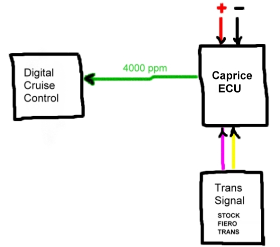
Use a Caprice ECU instead of a buffer and make only enough connections to get the signal to the digital cruise control. Can you verify that this diagram is do-able ? i guess my biggest question is whether the Caprice ECU will connect to, and work with, the fiero trans sender AND whetther teh Caprice ECU will work / output the 4000 ppm signal with minimal wiring. We KNOW that the 4000 ppm signal from the Caprice ECU will work
[This message has been edited by PaulJK (edited 04-04-2008).]
IP: Logged
11:29 PM
PaulJK Member
Posts: 6638 From: Los Angeles Registered: Oct 2001
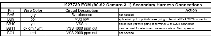
For anyone that has the 1227730 ECU sitting around and still has the stock fiero ECU in place and working, maybe you wanna try this (using the 7730 ECU in place of the buffer). I think these are the parts of ryan's diagram you wanna use - maybe he'll jump in and comment:
Is there an ON with IGNITION (ignition power) missing here ?
[This message has been edited by PaulJK (edited 04-04-2008).]
IP: Logged
11:58 PM
Apr 4th, 2008
Fino Member
Posts: 812 From: St. Johns, MI. USA Registered: Jan 2002
So you are saying that without installing a Digital dash from a 94 Caprice to get the 4000ppm speedo signal, this will not be workable. AND if that did work, I don't understand why KlingonFiero later installed a buffer connected to the VSS wires and used its signal to control the cruise control module.
That's what we've been trying to do (since we haven't installed a 94 Caprice digital dash anyway) and we're getting nowhere. Besides my friend and myself, Hurricane, ohio86se, and PaulJK haven't managed to get this working.
No doubt, it WILL be simple once someone else actually has it working with a stock Fiero VSS and ECM.
fierosound
What I was saying was sarcasm. I know it won't work that way but, I quoted klingonfiero because your not listening to me and I don't have time to waste working on this when it falls on deaf ears. I don't need this part to make my car work I was only trying to help other people get their car working and I do need to work on my car to get it done. I was waiting on input from people that have these parts allready in there hands and I was just going to another junk yard to get a buffer to try it when you asked about klingonfiero and you saved me time and money.
Seriously no hard feelings sorry I could be of no help
Ed
IP: Logged
06:24 AM
fierosound Member
Posts: 15145 From: Calgary, Canada Registered: Nov 1999
The other question is - is your friend sure that the digital cruise needs ONLY the 4000 (in the correct flavor) to work ? Is the hardware and installation otherwise functioning correctly ?
Agreed. He has 2 CC modules and can't get either to work. Just talked with him the other day and mused if there was any way to make sure the module is functional. It has power and ground, but how can you "bench test" it to make sure it responds when it gets the correct signal? Neither of us can find a diagnostic chart on how to bench test a module.
All our information is kinda half-assed at this point. We don't even know if all the electronic cruise control modules are the same. The only visual differences I can see are where the throttle cable connects to the module. Some cables are round, other are square. Do they all work with 4000ppm, or are some controlled by 2000ppm? Do you know?
Not arguing with you. As I mentioned earlier, just trying to sort through all this confusing information and get some specific information that will benefit us, such as (examples only):
Use a Yellow Buffer - these are found in 1987-92?? Pontiac Firebird V6 and... Connect only the yellow VSS wire, leave the purple unconnected. Use a cruise control module marked AG from Pontiac models only 1992-1995?? White buffers from Chev will not work. they only output 2000ppm?? Cruise control modules marked AS will not work?? (**********the above is just an example**********)
As you've stated, you have a yellow buffer "working properly". Let us know what specific CC module you get working with it and we will be grateful as we will be able to duplicate what you've done to get a working electronic cruise control. I do hope we can figure something out and get everyone who's started this project up and running.
IP: Logged
09:38 AM
fierosound Member
Posts: 15145 From: Calgary, Canada Registered: Nov 1999
Seriously no hard feelings sorry I could be of no help
Ed
No hard feelinga at all about anyone here. I apologize if I sound argumentative.
It's just that IF anyone with a Fiero using a stock VSS and ECM, made the cruise stalk wiring changes, wired in a yellow VSS buffer and connected an electronic cruise control module (sounds simple enough) and got it functional - we haven't heard from them.
[This message has been edited by fierosound (edited 04-05-2008).]
IP: Logged
11:50 AM
Fino Member
Posts: 812 From: St. Johns, MI. USA Registered: Jan 2002
No hard feelinga at all about anyone here. I apologize if I sound argumentative.
It's just that IF anyone with a Fiero using a stock VSS and ECM, made the cruise stalk wiring changes, wired in a yellow VSS buffer and connected an electronic cruise control module (sounds simple enough) and got it functional - we haven't heard from them.
Sorry you can't get your buffer working. I sure hope you find a way to get it to work.
Going back to installing the cruise, I have mine on the car ready to go I just need the chip for my 7730. You need to adjust your cable when you have mounted and I could not include a photo earler. The photo shows the adjuster that you lift op on the tabs top/bottom and the cable will move freely. You need to move the cable in/out to adjust the slack in the cable to be none BUT it does not hold the throttle off idle. The symptoms you will see if the cable is not adjusted correctly will be a very late engagement. This means you push the button at 60 mph and the car slows to 55 or 53 before it starts to pickup speed and also hunts while engaged, giving you very poor mpg.
One thing I would like to bring up if you cannot get your cruise to work is to check pin "H" needs to be either grounded or not grounded depending on vehicle origin. If people find the their cruise code (such as AR) needs to be grounded or not grounded, I will keep track on the first page if you send me a PM. This will help others as they install their cruise.


 . if i can find a turbo set-up at a good price, i'll throw that in with this project too.