I have successful relocated the Ignition Module and the Ignition Coil. This has been done on 2 Formulas and both cars have been running this way for more than 2 ½ years. I no longer have issues with the Ignition Module burning out. I have been driving worry free for over 2 ½ years.
My cars for some unknown reason would go through Ignition Modules like crazy. I got fed up with breaking down and decide to try and solve my module problem. My first test was to determine how hot the Mod would get. So I started the car with the mod outside of the distributor housing. I discovered how quickly the Mod got hot and the car will run with the Mod outside of the Distributor Housing. With that much heat it obvious that the stock Heat Sink was way undersized and poorly designed. I considered placing a larger Heat Sink with large fins but there was still and issue of no cool air movement across the Distributor.
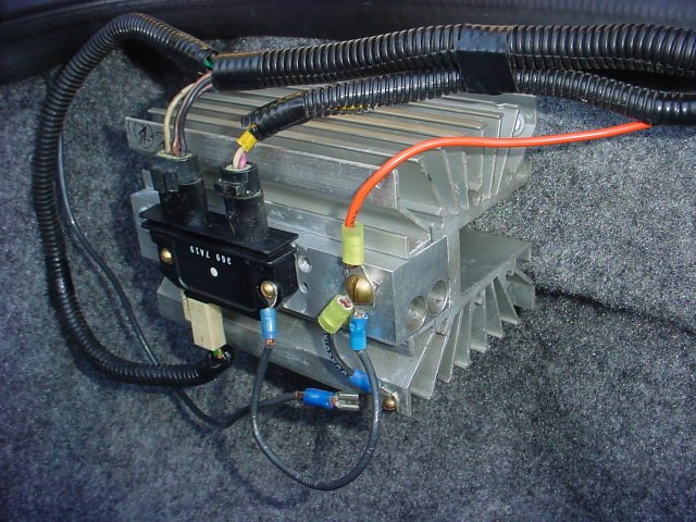
The pics show 2 different methods of relocation for the Ignition Module and 1 relocation for the Ignition Coil. The trunk mounted Mod works just fine but the trunk is sealed and it does get warm from the heat from the Mod. Plus it is easy to work on. The quarter panel mounted Mod is by far working the best for controlling the heat issue. Its down fall is it difficult to work on but I know you guys will find a better location.
The Coil relocation was simple. I found out early how heat shorts its life. I had a fairly new Accel Coil and the heat caused the Coil fail and caused the engine to back fire. I have not replaced a Coil nor have I experienced any more back fires.
Back to the Pics. Anything labeled A,B, and C are Coil related. A is the Ignition wire from the Coil to the Distributor. B is the 12vdc wiring to power the Coil. C is the just the Heat Shield still used to help keep heat off of the Pick Up Coil.
Label D is the location that I spliced wiring to operate the Mod that is mounted in the quarter panel. E is the wiring for the 2 wire plug into the Mod. As you can see I also have a plug for disconnecting. F is the wiring for the 4 wire plug into the Mod. Again you can see a disconnect. Those disconnects are used if for any reason I had the remote Mod fail, I still can use the original location on the Distributor to run the car. It made sense to have a back up plan.
I forgot tonight is Halloween and have too many Trick or Treaters. I hope this tread can help someone stay on the road! Larry
IP: Logged
08:58 PM
PFF
System Bot
steve308 Member
Posts: 4071 From: Stafford VA Registered: Jan 2008
All the wiring came from a Fiero in the junkyard. Once I had all the parts, I added wire by soldering them together to make the connectors long enough. The biggest challenge I had was how to connect the Pick Up Coil. I took an old Mod and broke the center out and took out the electronics and wired jumpers between the correct electrical tabs that the electronics were soldered on to. I think I will work on an electrical drawing and some more pics on this.
On the cars wiring harness, keep in mind I never snipped off the original connectors. I left them, in case my modification failed.
The Coil Wire came from Pet Boys. They sell a 5 footer which worked perfect for my modification
IP: Logged
12:37 PM
Patrick Member
Posts: 39385 From: Vancouver, British Columbia, Canada Registered: Apr 99
With that much heat it obvious that the stock Heat Sink (the base of the distributor) was way undersized and poorly designed. I considered placing a larger Heat Sink with large fins but there was still an issue of no cool air movement across the Distributor.
After reading about what you’ve modified, I might try combining what you’ve done with your coil with what I was discussing Here.
If I was to relocate my coil (which now seems relatively simple to do), I could then add an extension to my trunk fan tube to point it directly at the heatsink which I’ve attached to the bottom of my distributor. A lower temperature fan switch would take care of turning the fan on at a lower temperature than the stock one which seems to wait until the coolant temp reaches the surface temperature of Venus.
Here’s a picture of my engine with the trunk fan tube indicated:
What did you use to extend the wires that normally plug into the top of the coil (which I understand you did by not altering the original wiring harness at all)? In other words, what did you plug those two fittings into at the top of the coil that you can see in my image above?
Larry, I might just add that you could reduce the file size of your images to about 100kb so that it isn’t necessary for everyone to click on icons to actually see your images. Like this...
[This message has been edited by Patrick (edited 11-01-2008).]
IP: Logged
05:04 PM
larryfiero Member
Posts: 40 From: wheat ridge colorado usa Registered: Apr 2002
Patrick, Placing an extension is a great idea. Having cooler air blowing on the Heat Sink will definitely help your Ignition Module from not failing. By relocating your Ignition Coil, you open up a clear path to place an extension. Good thinking.
As far as fabricating the Coil Wire Extension. It is an easy modification to do. I used the same type of plugs that plug into the Coil. Cut what I needed from a Fiero in the junkyard. The wiring will be about 6 inches long and soldering 5 feet of new wire will get the job done. After I made my Plug Extension , I had to tap into the original Coil Wiring. You would need to find a spot near the original Coil Plugs and cut the insulation and solder together.
I felt it necessary to use the same Coil Plug so it would snap in place and not come off.
As far as reducing my pics to 100kb. I am using photo bucket. I have something new to learn. In the mean time bear with me, I need to have some one show me how to what you are asking.
If I did not answer your question, please let me know?
IP: Logged
09:04 PM
Nov 2nd, 2008
Patrick Member
Posts: 39385 From: Vancouver, British Columbia, Canada Registered: Apr 99
After I made my Plug Extension , I had to tap into the original Coil Wiring. You would need to find a spot near the original Coil Plugs and cut the insulation and solder together.
Ah, I misunderstood what you had done. I thought you had fabricated extension cables with male fittings on one end and female on the other.
Since you had to "tap into the original Coil Wiring" anyway, I think what I'll do is simply cut the original coil wiring and add several feet of appropriate wiring to it. Saves me the trouble of having to find a second set of terminals.
One question - Does the coil itself need to be grounded?
As far as re-locating the coil, I think a good spot might be in the area where the air intake/water separation box is located. It's relatively easy to gain access in there by removing the driver's side rear wheel well.
This will have to wait though until I find/fix what appears to be a plugged cat and/or muffler (as mentioned Here).
[This message has been edited by Patrick (edited 11-02-2008).]
IP: Logged
03:48 AM
Nov 3rd, 2008
larryfiero Member
Posts: 40 From: wheat ridge colorado usa Registered: Apr 2002
Patrick, that is a no on grounding the base of the Distributor. I did an continuity check and the base in not eclectically tied in with the four wires on top. I use a MSD Distributor and to verify, I contacted them and they said no.
IP: Logged
01:26 PM
Patrick Member
Posts: 39385 From: Vancouver, British Columbia, Canada Registered: Apr 99
Patrick, that is a no on grounding the base of the Distributor.
Larry, could you please clarify this? You've mentioned the distributor, but I was asking about whether there was a need for the ignition coil to be grounded. Thanks.
IP: Logged
02:08 PM
larryfiero Member
Posts: 40 From: wheat ridge colorado usa Registered: Apr 2002
Sorry about that. I can’t believe that I slipped up like that. That is a no on grounding the base of the Ignition Module. You can mount it anywhere that works for you.
IP: Logged
05:45 PM
Patrick Member
Posts: 39385 From: Vancouver, British Columbia, Canada Registered: Apr 99
Sorry about that. I can’t believe that I slipped up like that.
Oh, don't be too hard on yourself. It happens to the best of us.
Thanks for the info on the coil not needing to be grounded. I suspect I'll be mounting it on some metal part anyway, but I didn't want to run a supplementary ground wire to the engine block if it wasn't required.
IP: Logged
07:22 PM
PFF
System Bot
TXGOOD Member
Posts: 5410 From: Austin, Texas Registered: Feb 2006
Where did you get the connector that plugs into what would normally be where the pick-up coil plugs in. I have been working on a remote ignition module, and have found all of the pigtails for all of the connections except the one that plugs into the 1/8" tabs on the module. Did you also splice the wiring to the pickup coil or do you have a plug connector there as well. Mike Nevermind, I just read further about how you modified an old module.
[This message has been edited by TXGOOD (edited 11-03-2008).]
IP: Logged
11:11 PM
Nov 4th, 2008
larryfiero Member
Posts: 40 From: wheat ridge colorado usa Registered: Apr 2002
TXGOOD, I have been looking at the Pontiac Fiero Service Manual and I could not remember how critical the Pick Up Coil polarity is. The book shows a simple Coil feeding a Amplifier. The book does not specify and now I remember that I wanted to be safe than sorry. So I keep track of my polarities.
I have not mention this for the Pick Up Coil. I did not want to cut off the Plug on the Pick Up Coil. I wanted the ability to slap a good module back in if I had failures. There isn’t much room under that Distributor Cap.
I did however considered splicing and soldering the Pick Up Coils 2 wires and not cutting off the Plug. I was going to do this by running the wires through the opening where the Ignition Coil would have been or make a hole or slot to run the wires out through the side of the Distributor Cap. I decided it was probably best to modify and reuse an old Mod to help keep the Distributor Cap somewhat sealed.
I’ll have a pic of my gutted and rewired mod soon. L
IP: Logged
01:16 AM
larryfiero Member
Posts: 40 From: wheat ridge colorado usa Registered: Apr 2002
Here is a Pic of the modified Module. You can see the 2 wires I had to add to complete 2 circuits from one connector to the connector. Using the 2 pin connectors only. The 4 pin connector is not used. To find the proper tabs I had to do a continuity test.
IP: Logged
02:10 PM
steve308 Member
Posts: 4071 From: Stafford VA Registered: Jan 2008