I made a couple individual posts about different subjects, but decided to clump them all here into one. I'll add more as I make progress. (Can y'all stand another build thread?)
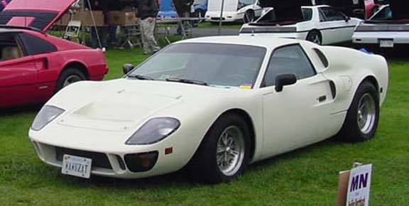
First, here's the car in which I'll be installing a '95 Northstar with 4T80E transaxle. This photo was taken at the Fiero gathering at Carlisle in 2002.
I've been working on this car since 1992 when I installed the NAF (prior to becoming ASPP) GT40 MKII body kit. I've got the body mods where I want them, the suspension has been completely redone, though I'll probably add a heavy rear anti-swaybar after this N* swap.
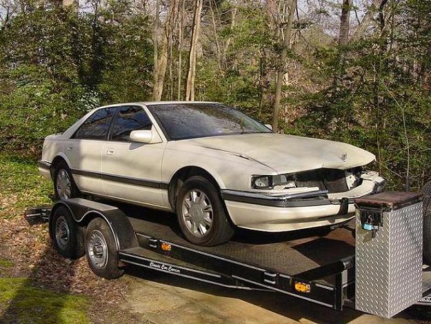
Here's a shot of the donor car for the Northstar drive train ... a 1995 Seville SLS ... VIN-Y engine. This pic was taken in March of 2005.
This is going to be a fun rip-out ...
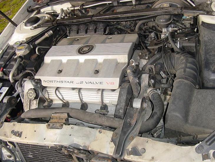
In June of 2005, I finally got around to yanking the drivetrain from the Caddy ...
Will add some more in a while. ------------------ GT40 rebody on an '85 GT ... soon to have N*-power // '05 Excursion // '05 Mustang // '06 Harley
[This message has been edited by WAWUZAT (edited 06-02-2007).]
IP: Logged
08:58 PM
PFF
System Bot
WAWUZAT Member
Posts: 563 From: Newport News, VA Registered: Jun 2002
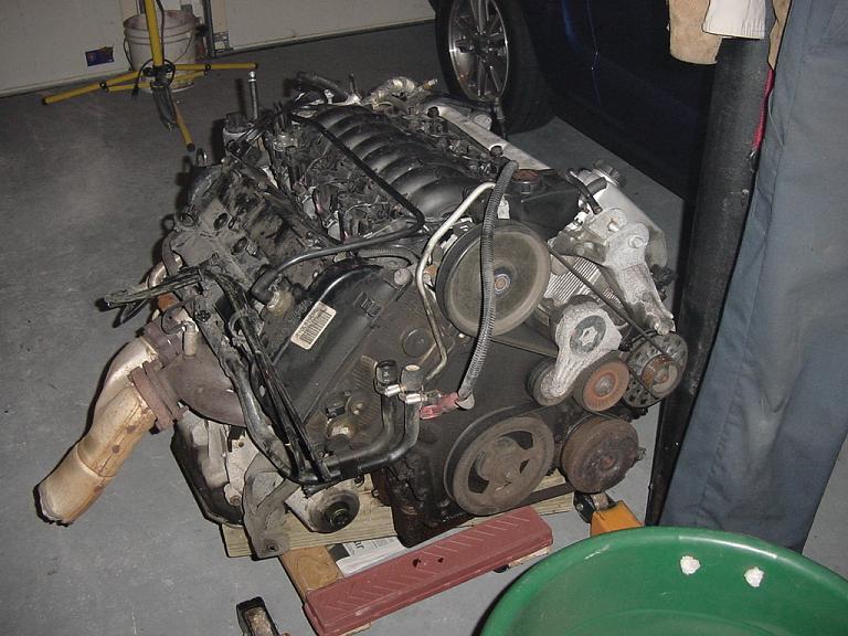
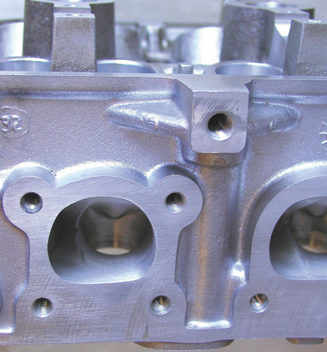
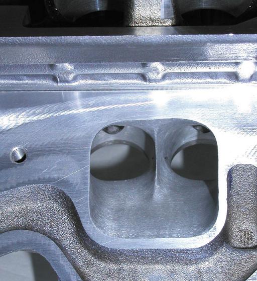
The N* sat on that moving dolly for a couple years. I've been busy building an item I designed for Ford Excursions (google "Landyot" if you want to see that stuff). While the engine sat, I did a little research, and a lot of drooling at the CHRF website. While there, I found a couple images on porting N* heads. The following two pix show the D-shaped exhaust port, and the knife-edge inside the intake port.
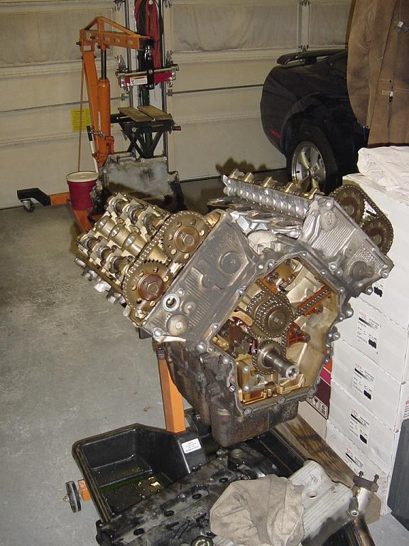
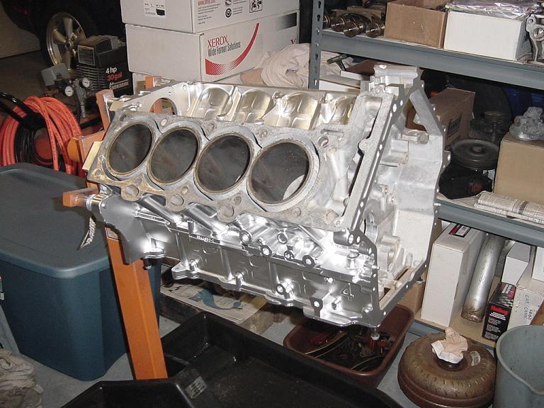
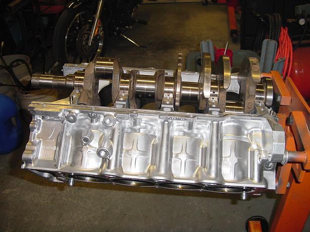
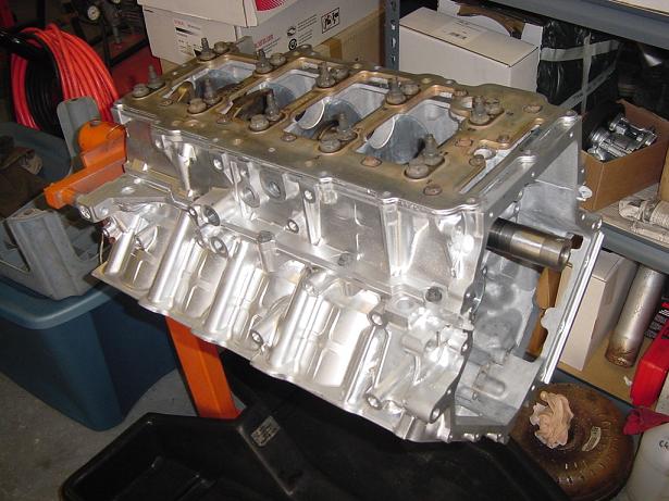
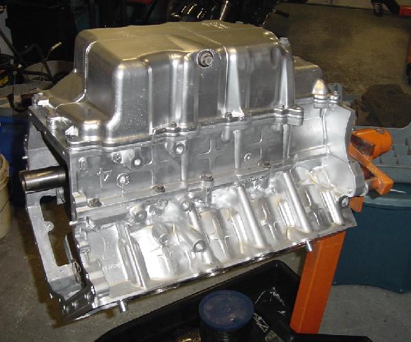
This year is the year I'll get this swap done, but since the engine had 150K miles on it, I wanted to do a basic rebuild first. I want her to last at least another 100K miles before having to pull it out of the car again. Of course, that assumes I won't be hankering to do some high performance mods ... like bigger camshafts. Here's a naked shot of the N* on the engine stand.
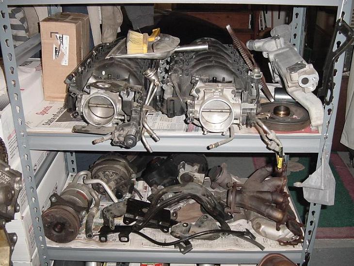
And some of my parts stash, which includes an extra intake that has the newer metal fuel rail. Man, I love eBay!
More later.
IP: Logged
09:09 PM
WAWUZAT Member
Posts: 563 From: Newport News, VA Registered: Jun 2002
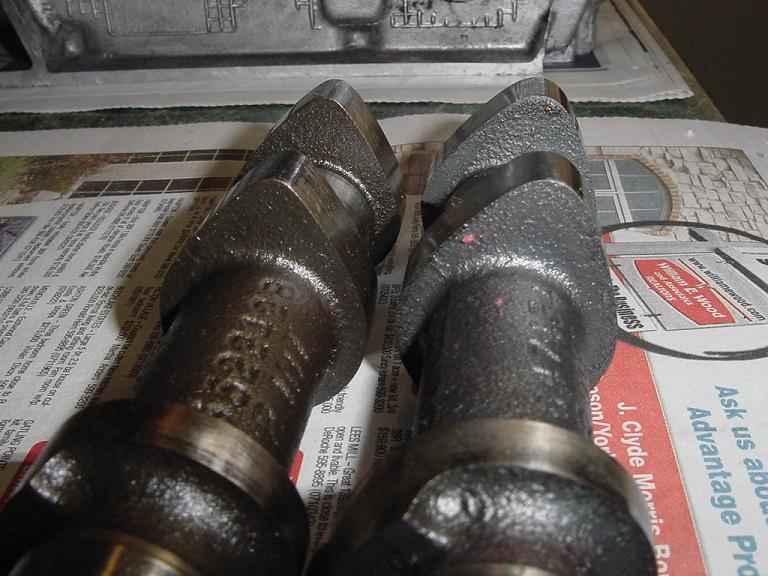
I guess I should clarify that the two pix above of the int & exh ports were copied from an article about CHRF. Elsewhere in this forum, I posted the following pic that compares the VIN-Y (shown on the left below) & VIN-9 (on the right) camshafts. I bought a pair of rebuilt heads on (you guessed it) eBay that were advertised as being VIN-Y. After measuring the camshafts, I was pleased to learn I had scored a pair of VIN-9 heads.
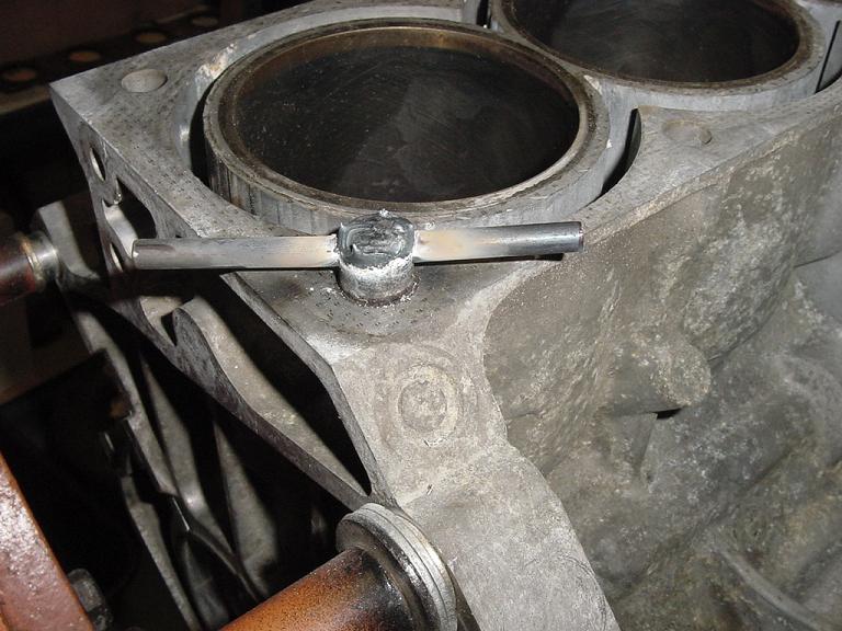
I had a tough time getting the dowel pins out of the cylinder decks. After ripping the end off of one, I welded a 1/4" rod that was inserted through a drilled hole, and wedged them out. Even with this method, I still had to apply a little heat to one corner in order to get the aluminum block to let go of that wimpy little dowel.
This past weekend saw me cleaning the exterior of the block, crankcase & oil pan, and get some paint on them before the nor'easter blew into town ...
The exterior had previously shown some oxidizing, and I don't want to see that stuff again.
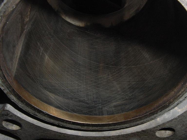
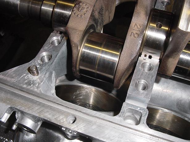
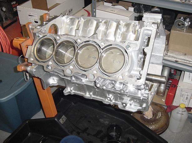
You can still see the original cross-hatching in the cylinder walls ... and this is after 150K miles!
That ugly looking stuff hanging inside the cylinder on the left side of the pic above is nothing more than some residue after having the block cleaned at a local machine shop.
OK, that's enough for tonight.
[This message has been edited by WAWUZAT (edited 04-16-2007).]
IP: Logged
09:22 PM
ryan.hess Member
Posts: 20784 From: Orlando, FL Registered: Dec 2002
You can still see the original cross-hatching in the cylinder walls ... and this is after 150K miles!
That type of crosshatch is not good. It is a compression leak. In the near future " next 5 years" you will see a big change in cylinder wall finishing. . . Normal production engine. Factory build and most Machine shops. You bore the block out and the bore square for the most part. Next it is honed very course. Like a cheese grater on bondo. Next it is honed Finer about 120 grit. This may be the end for some stock applications. Next it may be honed to 240 grit even at the factory. This was not to common 10 years ago. The cross hatch is in place the hold oil and lube the cylinder walls. The ring that are used in todays vehicles ar for the most part low tension. If I remember correctly something like 80% of all the drag in an engine is in the cylinders. It is mostly the rings. Now most top rings are rounded for better sealing. I will look for more info . . Set up a login and look at this http://www.cleviteelearning.com/index.aspx http://engineparts.com/
IP: Logged
02:35 PM
GKDINC Member
Posts: 1813 From: East Tawas MI Registered: Dec 2001
I read an interesting thing while researching welding on aluminum. Aluminum oxide (that oxidation you said you don't want to see) is second in hardness only to diamonds. It is very thin though. Melting point is higher than steel. (1200 pure aluminum versus 2300 for steel versus 3300 for aluminum oxide).
Its hardness is why aluminum oxide is used for a grinding medium.
IP: Logged
04:01 PM
WAWUZAT Member
Posts: 563 From: Newport News, VA Registered: Jun 2002
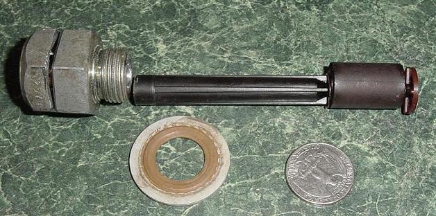
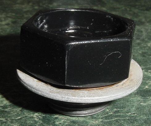
I'll be using a Holley 950 Commander "Pro" engine management system (Thanks, Daviero!), and it does not utilize the Northstar's oil level sensor. I could just screw the old one in the oil pan and hope it never leaks, but I've seen oil sensors go bad before ... once in my own car. What a mess, let alone almost frying an engine. So I cut up the old sensor as shown in this pic ...
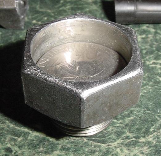
The quarter? It fit so nicely inside the old sensor housing, that I'll silver-braze it tomorrow to make a solid plug ... with no worries of oil leaks. I'll use Grade IV silver solder for brazing ferrous to non-ferrous metals.
------------------ GT40 rebody on an '85 GT ... soon to have N*-power // '05 Excursion // '05 Mustang // '06 Harley
IP: Logged
08:17 PM
WAWUZAT Member
Posts: 563 From: Newport News, VA Registered: Jun 2002
Originally posted by ryan.hess: Looks like you had a leaker! You replacing the case half seals? What are you going to do to it? Or have you decided yet?
Yeah, this block was filthy on the outside, but the internals were in terrific shape. At assembly time, I'll follow the instructions of a TSB document that AJxtcman posted (or sent me ... I forgot how I got it, but I saved it on my PC) using a special GM RTV-type sealant. In fact, I already have a couple tubes of the stuff on hand.
IP: Logged
08:24 PM
WAWUZAT Member
Posts: 563 From: Newport News, VA Registered: Jun 2002
Originally posted by AJxtcman: That type of crosshatch is not good. It is a compression leak. In the near future " next 5 years" you will see a big change in cylinder wall finishing.
AJ - Are you saying I should not use a similar method of honing my cylinders as the engine originally had? While the cross-hatching inside my cylinders is still visible, the cylinder walls have a shiny glaze. Also, the ring ridge at the tops of the bores only measures about 0.001" to 0.002" ... not enough to use a ridge-reamer IMHO. I was going to run a hone with medium grit stones through the bores, using kerosene as a wetting solution, and make only 5 or 6 passes. Now you got me wondering.
IP: Logged
08:32 PM
Apr 18th, 2007
AJxtcman Member
Posts: 1098 From: Rock Hill SC Registered: Nov 2006
If the bore is not square and you can help it become square without oversizing it out of clearance spec then a light hone is good. . . First you need to scrub down the block. I use liquid floor soap "simple green" this is a water based degrease. I use scotch brite pads either the green or maroon pads. You will need to wash the block off with lots of water and then apply a moisture displacement oil. I used CRC for years in 55 gal drums. WD40 will work. I now dry the block and spay it with ATF. Now you can get an accurate reading. It is amassing how much is built up on the cylinder walls and how much the reading vary from before the block was scrubbed. . . If you find the tapper at .002 - .003 I would not be concerned. If you find the Out Of Round at .002 - .003 you could hone .001 out if the piston clearance does not go above .002 If you find the Out Of Round at .003 - .0039 you will be OK, but do not touch the block. If you find the out Of Round above .004 You will need to do something else. another block? I have an alternative repair.
--Piston Clearance @ 41 mm below deck face ........0.0008-0.0020 in
--Cylinder Bore Out-of-Round -- Maximum ...............0.004 in
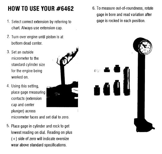
--Cylinder Bore Taper -- Maximum ..........................0.004 in . . . .004 is junk as the industries standards is .002. This is the service spec for a Northstar. Before I started at this dealer they had a Machinist would come in and measure the bores. He found them all junk. He was looking at .002 or less as a rule of thumb. . ----=-Cylinder Bore Taper Measurement Procedure #1 Measure the cylinder bore along the thrust surfaces (perpendicular to the crankshaft center line) at 5 mm (0.20 in) below the deck surface and record your measurement.
#2 Measure the cylinder bore along the thrust surfaces (perpendicular to the crankshaft center line) at 102 mm (4.00 in) below the deck surface and record your measurement.
#3 Calculate the difference between the two measurements. The result will be the cylinder taper.
#4 Compare your results with the engine mechanical specifications. If the cylinders exceed these specifications, replace the cylinder block.
--------Cylinder Bore Out-of-Round Measurement Procedure #1 Measure both the thrust and non-thrust cylinder diameter 5 mm (0.20 in) below the deck surface. Record your measurements. #1B Calculate the difference between the two measurements. The result will indicate out-of-round at the upper end of the cylinder.
#2 Measure both the thrust and non-thrust cylinder diameter 102 mm (4.00 in) below the deck surface. Record your measurements. #2B Calculate the difference between the two measurements. The result will indicate out-of-round at the lower end of the cylinder.
#3Compare your results with the engine mechanical specifications. If the cylinders exceed these specifications, replace the cylinder block.
------------------ Cadillac Tech ASE MASTER TECH since 1988 86 Northstar Fiero 85 RX7 former SCCA car 56 TR3 small mouth 6.0L Formerly Washougal WA Resident A.J. Whiteley
IP: Logged
07:52 AM
PFF
System Bot
AJxtcman Member
Posts: 1098 From: Rock Hill SC Registered: Nov 2006
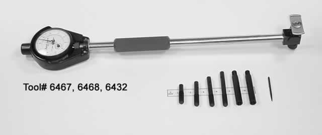
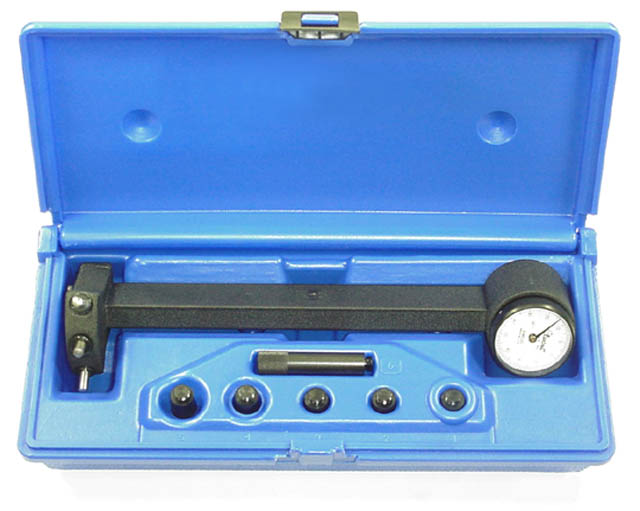
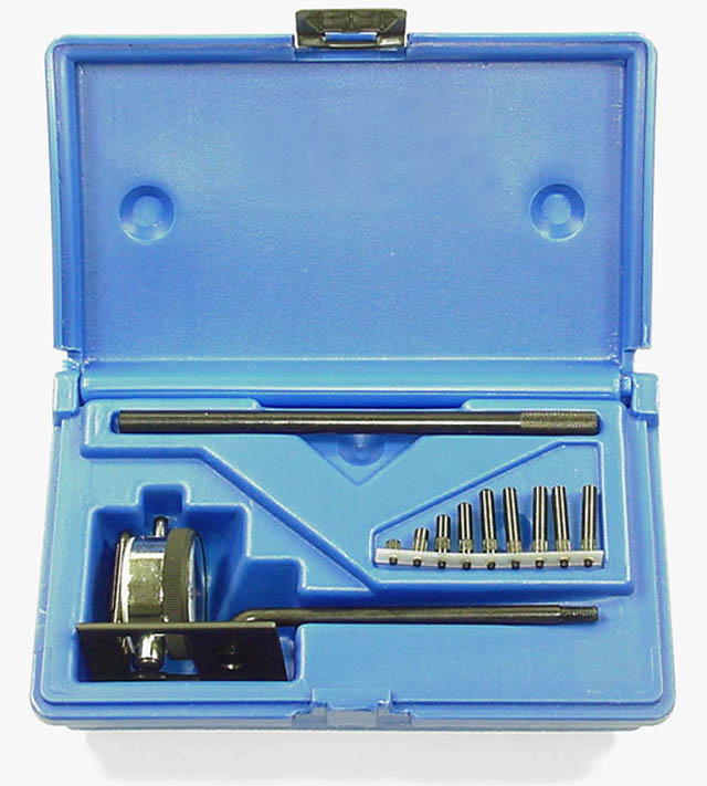
This would be a nice cylinder bore gauge . . . This is a middle of the road gauge and the one I use. . . This is a cheap one and it will take some extra time to get acurate readings . . Instructions from central tools.
IP: Logged
02:26 PM
Apr 21st, 2007
WAWUZAT Member
Posts: 563 From: Newport News, VA Registered: Jun 2002
Had a machinist friend come over today and we measured most everything. In return, I did some welding for him. I've yet to analyze the numbers ... will plug & chug 'em using an Excel spreadsheet ... but the bore diameters are all within 0.0015" of each other at high/mid/low locations in both longitudinal & transverse directions. I also found an error in the spec's listed in the GM factory service manual. More details on that later.
Finished silver-brazing & painting the plug I made from the old oil level sensor.
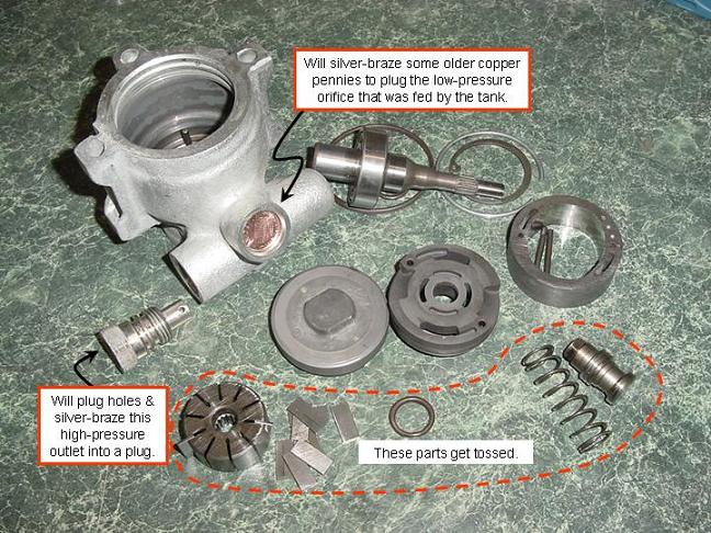
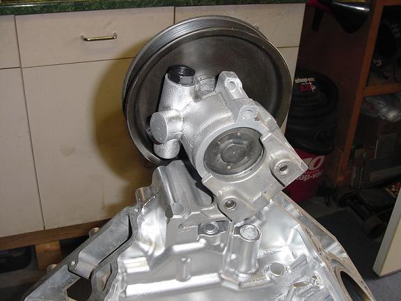
A few years back, I fit a 3800SC engine into a buddy's Fiero (all I did was get the engine in the car, modify his cradle & fabricate the motor mounts, he did all the outfitting work). During that swap, we decided to keep the 3800SC's serpentine belt pulley arrangement, and just modify the PS pump's plumbing. What we did was route the high-pressure line right back into the tank with a small orifice fitting inline to provide some fluid restriction (keep turbulance & foaming down). This time with my N*, I got a little more brave and disassembled my PS pump. Turns out that I can remove the pumping vanes, plug the holes, fill it halfway with oil, and ditch the reservior tank. Another photo ...
[This message has been edited by WAWUZAT (edited 04-21-2007).]
IP: Logged
08:04 PM
Apr 22nd, 2007
WAWUZAT Member
Posts: 563 From: Newport News, VA Registered: Jun 2002
OK, now I am somewhat concerned, and not sure what I should believe. I'm losing confidence in the GM data.
The GM manual says the cylinder bore is "93 mm (3.66 in.)", but when I convert 93 mm to inches, I come up with 3.6614 in. All of my cylinder bores measure 3.664" to 3.665" diameter at (near) top/mid/bottom locations in both longitudinal and transverse directions.
On another page, the GM manual says the (crankpin) rod journal diameter on the crankshaft is "53.995 mm (0.069 in.)" WHAT??? By my calculations, 53.995 mm equals 2.1242 in. All of my rod journals measure 2.124" diameter.
The GM manual also says the crankshaft's main journals should be "64.358 mm (2.52 in.)". Again, I calculate 64.358 mm to equal 2.5338 in. All of my main journals measure 2.5330" to 2.5335" diameter.
My pistons still show the original machining surface around the skirts, and I have 0.0015" to 0.002" of clearance between the pistons and cylinder walls. The bores have no more than 0.001" out of round or taper in them. When I compare the crankshaft main journals against bearings inside the torqued down block & crankcase, I have 0.002" clearance. When I compare the crankshaft rod journals against bearings inside the torqued down connecting-rod & cap, I have 0.002" clearance. I haven't measured thrust dimensions yet, but after seeing the minimal wear on all these components, I'm not concerned about it (though I will double-check it when I assemble the bottom end).
If any of you have opinions on these findings, please chime in.
------------------ GT40 rebody on an '85 GT ... soon to have N*-power // '05 Excursion // '05 Mustang // '06 Harley
IP: Logged
11:23 AM
WAWUZAT Member
Posts: 563 From: Newport News, VA Registered: Jun 2002
I had a thought about another aspect of the N* swap. The front cradle crossmember must be moved forward. No big deal in and of itself, and fabricating a crossmember should be a breeze. Years back, I modfied the cradle to lower the car. But since the Northstar will require a cross-over tube for the cooling system, I'm curious if anyone has given any thought to making that front cradle crossmember function as the cooling system's crossover tube? I'll decide later whether to use round or square steel tubing for the crossmember, but sealing its ends, and plumbing in some hose connections could free up a little space at the forward end of the engine compartment.
IP: Logged
08:43 PM
Apr 24th, 2007
Totty Member
Posts: 149 From: Winchester, KY Registered: Aug 2004
i used 1" round tubing and welded some mandrel bends into it. turned out real nice and i can still fit factory style radiator hoses over it.
Totty - Are you saying you used 1" round tubing to make the front crossmember in the cradle? 1" O.D. tube or 1" NPS? Either way, I would think something more substantial would be needed. I'll probably use some square tubing (size yet to be deternined) and weld on some hose connections to route the coolant through it. I also like the idea of having that square tube penetrate through both walls of each side-rail in the cradle ... have it protrude to the outside of the cradle a bit to allow for more stiffness. This will also allow me to weld on a 90-degree hose fitting on the right-hand side, then use a fairly short rubber hose to connect to the under-chassis coolant pipe.
IP: Logged
09:02 PM
Apr 25th, 2007
WAWUZAT Member
Posts: 563 From: Newport News, VA Registered: Jun 2002
I've gotten to a point where I can install the NS300L head bolt inserts I bought via eBay. You can find those inserts on eBay by doing a search for "Northstar inserts" ... and I've heard several folks (and GM technicians) claim they're much better than Timeserts.
When I disassembled my engine, all the head bolts broke loose with a definite crack-crack sound. None of them eased out, which would be an indication of bad threads in the block. Being the cautious type, I wanted some sort of thread insert for when I torque the new head bolts down. The last thing I want is to wait until that time to find I really need them. It is so much easier to do it now while everything's disassembled, and cleaning out the drilling & tapping debris won't be a tedious task.
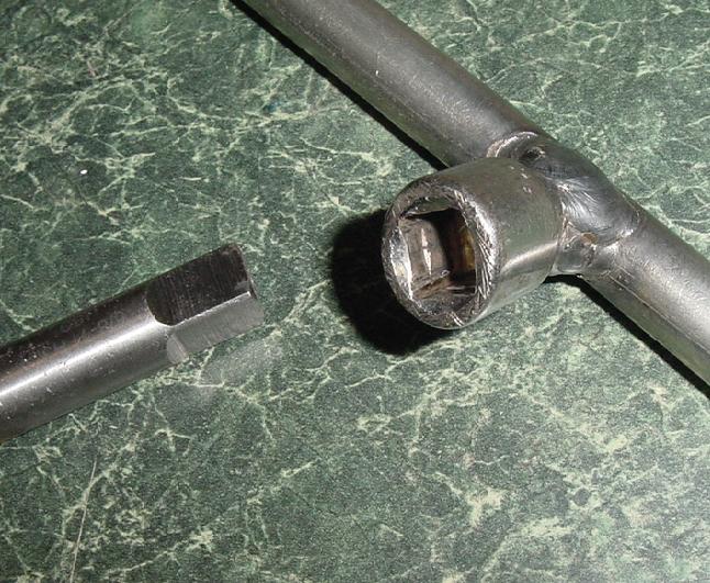
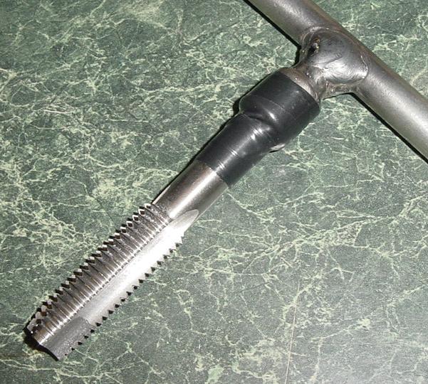
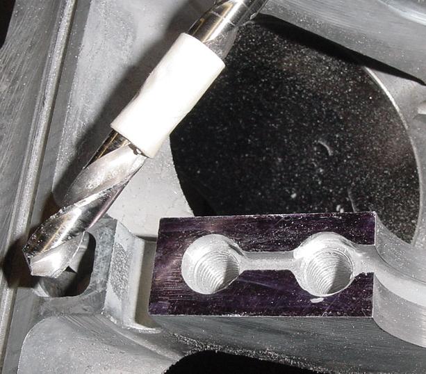
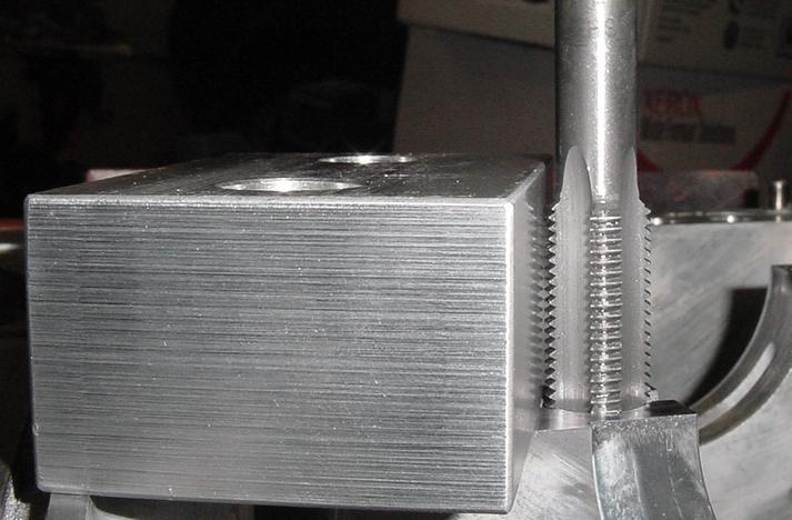
In the past, I've tapped holes that were 1/2" diameter and smaller. But I needed a larger tap-holder to use the taps that came with the insert kit, something that would accomodate a 3/8" square. I shopped around locally, but what I found was way too expensive ($70) for a tool that will only be used one time. Instead, and as shown in the following pix, I cut up an old broken 3/8"-drive socket extension, and welded it to a 1/2" diameter by 12" long round bar (a scrap piece I had left over from some other project). It's not pretty, and I have to tape the tap to the "driver" to keep it from falling out, but it works like a champ.
IP: Logged
09:07 PM
May 1st, 2007
WAWUZAT Member
Posts: 563 From: Newport News, VA Registered: Jun 2002
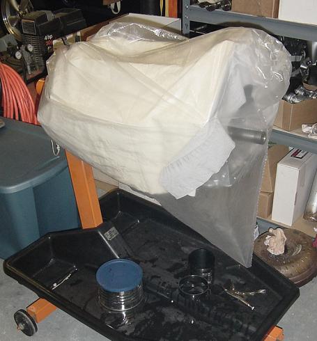
A week ago Sunday, we had a crew here replacing the front porch columns, posts & rails. I spent many hours over the last week caulking, sealing and painting the new stuff (composite columns & wood everything else). So, I've been away from the N* for awhile. Tonight, I gave the bores a very light scuffing with a hone (enough to break up the glazing), then did a final blow-out of the holes with compressed air, hosed off the block, and used the air again to dry everything. Then I lubed the cylinder sleeves (steel), put a plastic bag over it, and called it a night. I am now in assembly mode.
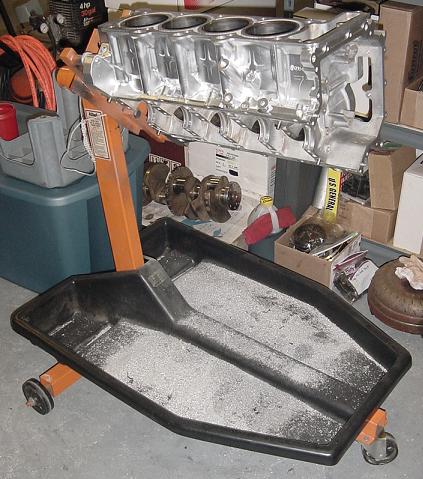
The photo below shows the amount of aluminum that got drilled and tapped out of the head bolt holes in order to install Norm Huhn's inserts ... which will be installed tomorrow evening. More importantly, the photo shows a relatively inexpensive item that saves a LOT of mess getting on the floor. I paid about $45 with shipping for that catch-all pan that rests on the legs of the engine stand. It caught all sorts of gook & oil during disassembly, the aluminum as shown, and will keep assembly oils from reaching the garage floor. This thing is well worth the money.
IP: Logged
08:39 PM
ryan.hess Member
Posts: 20784 From: Orlando, FL Registered: Dec 2002
Originally posted by ryan.hess: You should smooth out those windage holes while you've got the block on the stands... I think Will has pictures somewhere. That's like +10hp for free.
Ryan - Ya' made me go look! I did find the pix of the windage hole mods Will did on his block. While I can appreciate the purpose of rounding off those edges, I have my doubts that it's worth 10 HP ... 2 to 4 maybe, but 10? I'm also at a point where I'd have to reclean a lot if I attempted that mod now.
FWIW in the area of additional ponies, I will be doing some minor porting work on my cylinder heads. I'll contour the exhaust ports to a D-shape as shown in an earlier photo, but will not remove much from the runners. My goal is to D-shape the exhausts, knife-edge the splits between the valves, and then only smooth the cast surfaces. I think I read somewhere that CHRF removes almost 0.100" all around from the ports.
IP: Logged
09:06 PM
May 3rd, 2007
WAWUZAT Member
Posts: 563 From: Newport News, VA Registered: Jun 2002
Ryan - It now looks like I'll get the chance to deburr those edges on the windage holes. Read on ...
Tonight I was all ready to assemble the bottom end. New main bearings, crankshaft, crank case, and seal it up using information from AJxtcman's TSB document (use a GM sealant in lieu of gaskets). I had all the parts, bolts, and wrenches laid out in an orderly fashion. Also had a cardboard template pre-cut for torquing the main bolts. The GM manual calls for 15 ft-lbs first pass, followed by a second pass of another 65-degrees ... on all twenty main bolts. In lieu of a single pass at 65-degrees, I opted to make two passes at 32.5-degrees each ... a total of three passes over the tightening sequence.
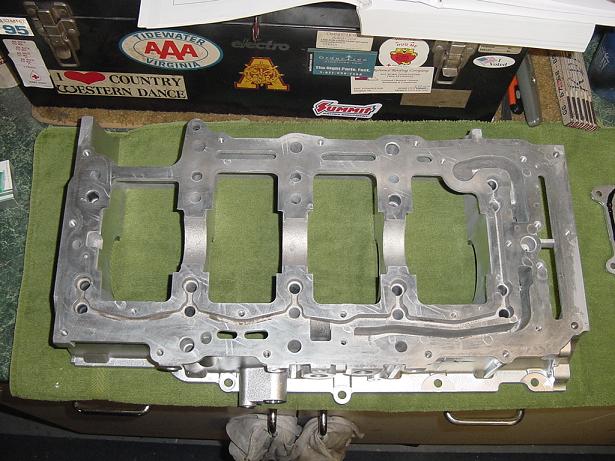
Here's the lower crankcase ready to go ...
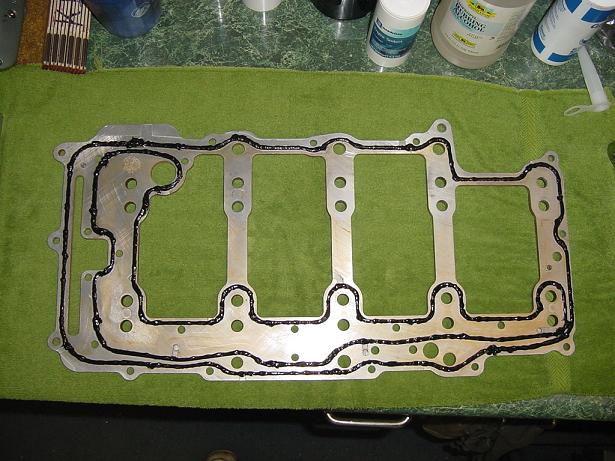
Here's the oil manifold with black RTV sitting awhile to allow the sealant to "skin" ...
Here's the block with the crankshaft in place, sitting on new bearings with a coating of assembly-lube ...
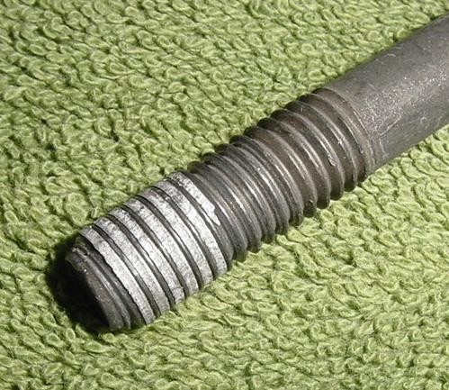
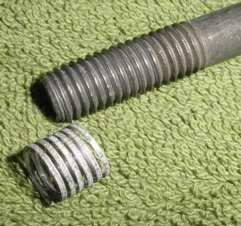
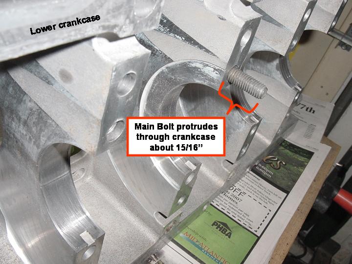
Then this happened !!! Caused me to use the French translation for "Darn it!"
Here's another shot ...
Months ago, I posed the question in this forum about inserts for the main bearing bolts. It just seemed like a logical progression if one installs inserts for the head bolts, that one should also do likewise for the mains. I was assured by some (will leave their names out of this post) that installing main bolt inserts was rarely, if ever needed. Looks like I found the need.
Anyone have any inexpensive sources before I go inquiring at a GM dealer? The manual says I'll need insert package R1084-10-20, insert length of 29.5mm, tap #2093-10, and insert tool 3747-10.
[This message has been edited by WAWUZAT (edited 05-20-2007).]
IP: Logged
08:56 PM
AJxtcman Member
Posts: 1098 From: Rock Hill SC Registered: Nov 2006
The Timesert kit is advertised for about $300 ... way too much $$$ for inserts that do not impress me much. Even if I did find a good deal on them at eBay, I'm reluctant to buy them. I already have the NS300L inserts installed in the head bolt holes, which means I already have all the tools on hand to install inserts with the same external thread (external thread is 5/8" x 11 TPI). I'll have a machinist friend of mine make me some shorter inserts with M10 x 10.5mm internal threads, then drill and tap the block to install those. Being that they're replacing aluminum threads, I would think that I could make the new inserts from Grade 2 threaded rod.
IP: Logged
09:27 PM
May 6th, 2007
WAWUZAT Member
Posts: 563 From: Newport News, VA Registered: Jun 2002
Ryan (and anyone else that's interested) - I got the block apart again this weekend, AND did the bay-to-bay window deburring treatment today as was discussed on page 6 of Will's N* thread ... https://www.fiero.nl/forum/F...2/HTML/044924-6.html
I did not break out the carbide deburring tips and pneumatic die grinders. All I did was run some strips of emory cloth through the holes to round-off the edges. Also used a small rat tail file to get at some edges. I believe the advantage of the rounded edges is to allow oil to weep down the walls easier, without accumulating inside each "window ledge" to eventually meet with a fast turning crankshaft. With the sharp edges removed, it's less likely the oil will experience liquid adhesion in close proximity to the crankshaft.
IP: Logged
07:46 PM
May 8th, 2007
WAWUZAT Member
Posts: 563 From: Newport News, VA Registered: Jun 2002
Originally posted by WAWUZAT:I already have the NS300L inserts installed in the head bolt holes, which means I already have all the tools on hand to install inserts with the same external thread (external thread is 5/8" x 11 TPI). I'll have a machinist friend of mine make me some shorter inserts with M10 x 10.5mm internal threads, then drill and tap the block to install those.
Well, I changed my mind after checking some dimensions, and decided against a 5/8-11 external thread. I'm going with a 9/16-18 external thread. First I looked at several aspects of the lower crankcase & block.
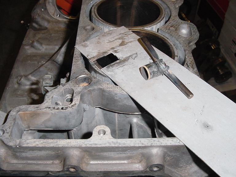
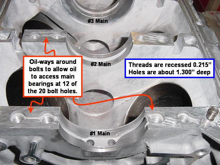
One thing I noticed is that the cast oil passages around the main bolts are not centered with the bolt hole.
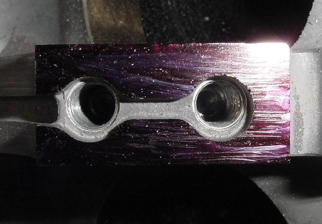
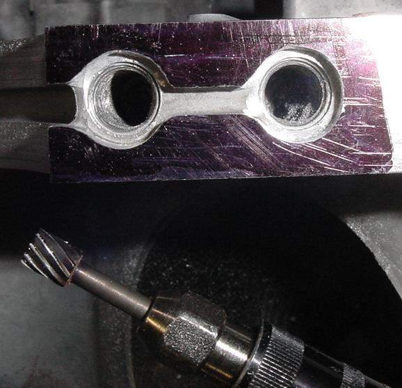
So out comes the Dremel tool and an appropriate bit for the task. This little bit of surgery is done so the 1/2" drill bit will not get hung up on the sides of the oil passages, and will allow the drill bit to stay centered.
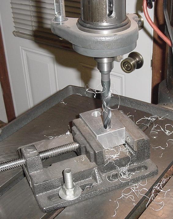
Actually, I drilled the holes open in three passes ... first with a 3/8" bit, then a 7/16", and finished with a 1/2" bit. Drilling the holes in steps allowed for much easier self-centering of the bits. Here's a shot after the first pass with the 3/8" bit ... barely removed the threads. You can also see my "poor man's" drill-stop (tape wrapped around the bit).
And here's a shot after the last pass with the 1/2" bit ...
[This message has been edited by WAWUZAT (edited 05-08-2007).]
IP: Logged
09:24 PM
WAWUZAT Member
Posts: 563 From: Newport News, VA Registered: Jun 2002
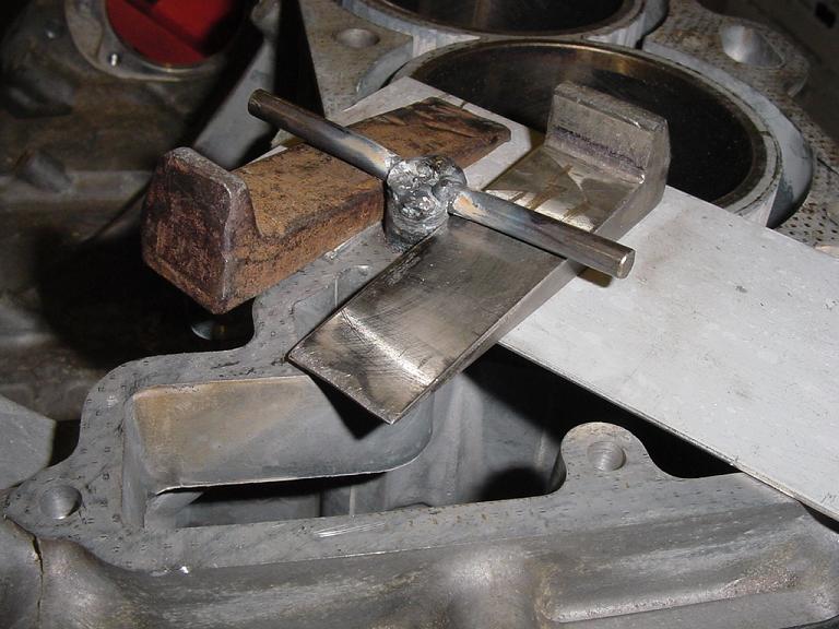
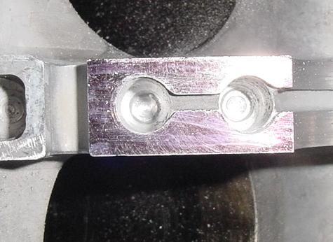
Before running the 9/16-18 tap into the holes, I need to make a guide block so the tap will remain square with the surface. Since I was finished using the guide block that came with the NS300L head bolt insert kit, I opened up the smaller hole in that block to 9/16" diameter.
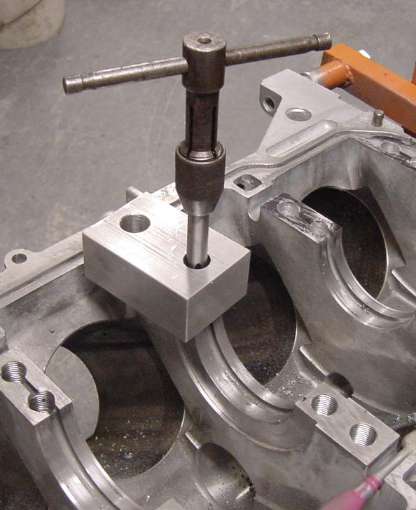
Here's the guide block in use while tapping ...
And the guide block comes in handy as a small square to ensure the tap is going into the hole at the correct angle ...
IP: Logged
09:31 PM
May 9th, 2007
WAWUZAT Member
Posts: 563 From: Newport News, VA Registered: Jun 2002
Finished tapping & bottom-tapping the main bolt holes tonight. The inserts should be in my hands early next week. So the next step is to roll this block outside, spray some degreaser on it (and in it), hose it off and blow-dry with compressed air. While waiting for the inserts, I can start making my own tool adapter to use with a valve spring compressor. I need to get the heads disassembled so I can do some minor porting work. Removing N* valves looks like it can be a tedious task. I tried to buy the GM tool adapter, but was told it's not available.
IP: Logged
09:06 PM
May 14th, 2007
WAWUZAT Member
Posts: 563 From: Newport News, VA Registered: Jun 2002
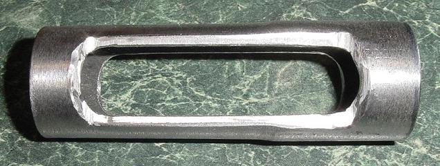
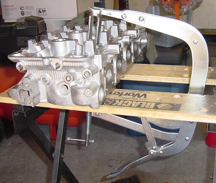
Fabricated an extension to be used with a valve spring compressor ... I used a 4" length of 1" NPS Schedule 80 carbon steel pipe, and turned it against a bench grinder to reduce the O.D. to where it will easily fit inside the cam follower holes with about a 1/16" clearance all around. Then I drilled a series of 5/8" holes along the side, removed the metal in between the holes, and finished with some long slots.
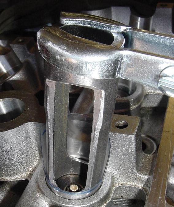
To protect the machined surfaces inside the cam follower holes on the N* heads, I cut up a 2-liter Pepsi bottle, and wrapped a piece of it a couple times around a valve spring. A Sharpie and a pair of scissors were the tools needed to make this item. This "protector" also came in handy when I was removing the valve seals.
And here's the tool being used to remove the valve springs from one of my heads.
IP: Logged
09:06 PM
PFF
System Bot
May 20th, 2007
WAWUZAT Member
Posts: 563 From: Newport News, VA Registered: Jun 2002
Some have said the only differences between the 275HP VIN-Y (LD8 engine) and the 300HP VIN-9 (L37 engine) are the camshafts and the valve springs. I posted a photo earlier that shows the physical difference between the camshafts. Just for kicks, I compared the valve springs today. The VIN-Y springs are wound from 0.125" diameter wire, and have six-and-a-half 360-degree coils. The VIN-9 springs are made from 0.130" diameter wire, and have only six 360-degree coils.
Spent yesterday getting my heads and valves ready to take to the shop. The valves need a minor grind, especially the exhaust valves. The seats look good, but they'll be touched-up, too. Some, if not all of the valve guides may need replacing ... at least I think they could stand replacing. Some of 'em "felt" like they were moving more than the 0.005" sideways tolerance. I didn't bother setting up my dial indicator to measure the movement.
When I took my connecting rods to the shop to have them replace the wrist pin bushings, they called me up and said there was no charge. The shop said the pin to bushing clearances were all within the GM-spec tolerance (0.0002" ... yes, 2 ten-thousandths), and that couldn't make them any better than they already are. Remember, this engine had 150K miles on it! I wish I could locate the previous owner so I could find out what lubricant he used.
Today was a miscellaneous parts clean-up & painting day.
[This message has been edited by WAWUZAT (edited 05-20-2007).]
IP: Logged
05:35 PM
May 28th, 2007
WAWUZAT Member
Posts: 563 From: Newport News, VA Registered: Jun 2002
Back to the main bolts ... My machinist buddy finally finished making the inserts for me. He had them almost three weeks, but since his daughter was home from Iraq for a couple weeks, I wasn't going to push him for the parts ... I can wait. Got them home, found they were a little long, (only by 1/8"), trimmed the lengths, pre-fit them in place, then final installed with Loctite.
Made a lot of progress today. Installed the crankshaft, then the pistons & rods with new rings and bearings. Dunked each piston in a can of fresh oil, and used Clevite77 assembly lube on all bearing surfaces.
Once assembly starts, cleanliness is very important, so the last thing was to tuck her in for the night ...
IP: Logged
08:28 PM
May 29th, 2007
WAWUZAT Member
Posts: 563 From: Newport News, VA Registered: Jun 2002
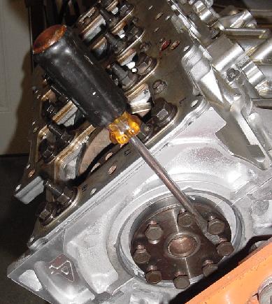
After spending most of yesterday assembling the bottom end, the only task left to complete the "short block" assembly was to torque the rod bolts. I installed all new torque-to-yield GM rod bolts, and the GM manual specifies tightening them to 18 ft-lbs plus 110-degrees. Well, the first order of business was to make turning the crankshaft by hand an easier task so I could get to all of the rod caps. Since I already have new flex plate bolts on hand, I screwed in the old bolts so I could turn the crank with a screwdriver ...
The first pass of tightening the rod bolts was simple since I used a click-type torque wrench set to 18 ft-lbs. However, turning 110* was going to be a challenge using the tools I have in house. I broke down the 110* into three 30* turns plus a final 20*. That way, I could use a magnetic-based degree indicator in a much easier method ... dangling on the bottom edge of the wrench handle.
IP: Logged
08:33 PM
AJxtcman Member
Posts: 1098 From: Rock Hill SC Registered: Nov 2006
AJ - Thanks for the links! I may order one for when I install the heads. I don't mind investing in tools when I think I will use them again.
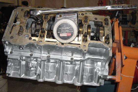
Got a little more done this evening. Installed the windage tray and oil pick-up tube. After reading another post where someone suspects their pick-up tube came loose, I dabbed some Loctite on my fasteners.
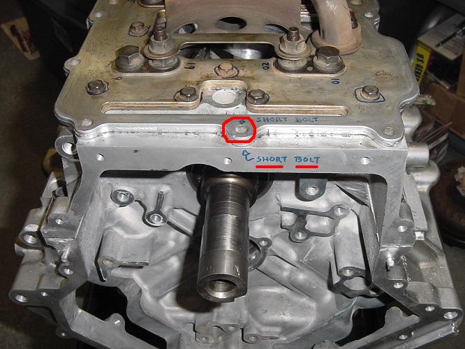
There is one short bolt among the 13 oil pan bolts, and I wanted to ensure I installed it in the right location. This tapped hole is more shallow than all the rest.
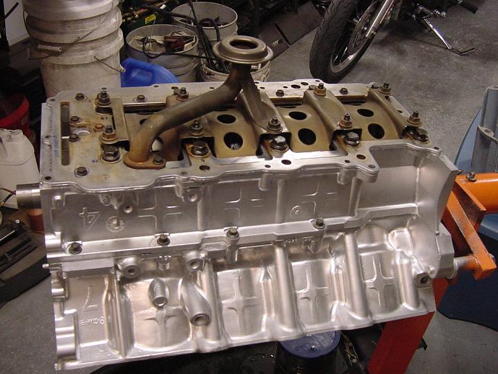
Finally, I got the oil pan on, and the bottom end is now all buttoned-up. I used a Fel-Pro neoprene gasket in the oil pan's machined groove, but backed it up with a small fillet of black silicone sealant ... ran a small bead around the inside, and tapered it using my finger.
[This message has been edited by WAWUZAT (edited 05-30-2007).]
IP: Logged
09:15 PM
AJxtcman Member
Posts: 1098 From: Rock Hill SC Registered: Nov 2006
Originally posted by WAWUZAT: The first pass of tightening the rod bolts was simple since I used a click-type torque wrench set to 18 ft-lbs. However, turning 110* was going to be a challenge using the tools I have in house. I broke down the 110* into three 30* turns plus a final 20*. That way, I could use a magnetic-based degree indicator in a much easier method ... dangling on the bottom edge of the wrench handle.
I tried to use a rod bolt stretch gauge on my Eagles, but only half the bolts are accessible once the lower crank case is bolted on... Next time I'm going to do the rods first.
IP: Logged
05:56 AM
AJxtcman Member
Posts: 1098 From: Rock Hill SC Registered: Nov 2006
Originally posted by WAWUZAT: Here's a shot of the donor car for the Northstar drive train ... a 1995 Seville SLS ... VIN-Y engine. This pic was taken in March of 2005.
Will - I gave a lot of thought to doing the rods before the crankcase, and I (obviously ... as shown in the pix) decided against it. I certainly can understand the advantages of doing the rods first, mostly for the extra working space. When I installed the pistons, I was turning this motor over and over on that engine stand to fit the bearings and rod-caps. To do the rods first, you'd have to install the pistons from below unless you fashioned some method to keep the crankshaft from falling out. Something else that didn't appeal to me was the idea of turning that crank many times with only the upper halves of the bearings in place. Granted, it wouldn't be hard to reposition them if they moved. I just wanted to avoid any scoring of surfaces if they did move ... worried about the surfaces between the bearing inserts and the block.