I'm having a troubles with a problematic 84 Speedometer. I don't know if it has ever worked because the car wasn't running when I got it. The needle doesn't even move when ignition is on (always sits at 0), so I assume the original speedo is dead.
I tried swapping in another speedo that I know is good and works (tested in my 87 GT). With this speedo the needle "sets" itself to 0 when ignition is turned on, so it's "live" and power and ground to speedo seems OK. But no other response when car is moving. Tried with another loose VSS (Vehicle Speed Sensor) that I plugged into the harness and spun with a drill in both directions, with no response.
I tested the yellow/purple wires in speedo connector with an ohm-meter - gets about 385 ohms. That's the same as what I get across the terminals of the loose VSS I have. That seems to indicate the wiring from VSS to speedo connector is intact.
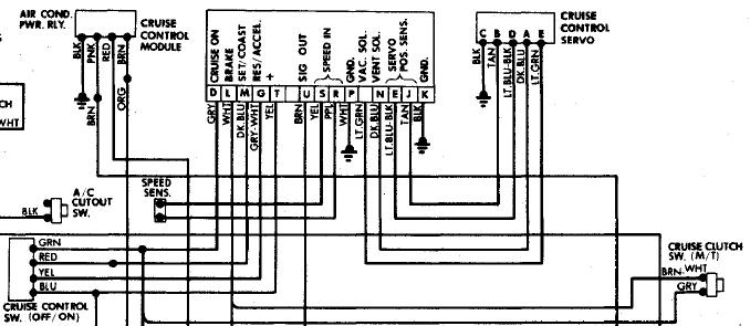
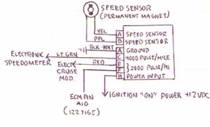
So I have, power, ground and VSS signals to the speedo, but the connector has 14 wires (84 unit with internal cruise control). It should be more correctly identified as Cruise Control/Speedometer Module for the 84 in this picture.
I was extremely careful, but I must have messed something up following this guys directions on replacing the cruise control. Mostly concerned with the wiring changes at the speedo end. https://www.fiero.nl/forum/A...030531-2-030708.html
Has anyone else done this upgrade on an 84? Maybe we can compare notes.
------------------ 3.4L S/C 87 GT www.fierosound.com 2002/2003/2004 World of Wheels Winner & Multiple IASCA Stereo Award Winner
[This message has been edited by fierosound (edited 11-01-2007).]
IP: Logged
12:06 PM
PFF
System Bot
Fiero STS Member
Posts: 2045 From: Wyoming, MN. usa Registered: Nov 2001
The 84 speedo with cruise is different from all others. I don't have any manuals in front of me but you could look at a newer cars connector and see if the purple and yellow from the speed sensor go to the same terminals. Also there is a ground wire that runs from the speedo back if this is bad the speedo won't work.
IP: Logged
12:26 PM
jscott1 Member
Posts: 21676 From: Houston, TX , USA Registered: Dec 2001
I tested the yellow/purple wires in speedo connector with an ohm-meter - gets about 385 ohms. That's the same as what I get across the terminals of the loose VSS I have. That seems to indicate the wiring from VSS to speedo connector is intact.
The 84 speedometer uses the same connectors for the VSS/Ground and power connections. An 85-88 speedo should work just for testing.
Putting an ohmeter across the VSS is not a reliable test. Those are AC signals that travel through those wires. What you need to do is a continuity from the Purple/yellow wire back to the VSS. Or better, get a signal generator and put it right to the speedometer and see if it works. I'm guessing from your description that you have bad continuity from the VSS forward through to te speedometer. Unlike later years the VSS DOES go through C500 and you might have a problem there.
IP: Logged
03:36 PM
SuperchargedV6 Member
Posts: 1966 From: Hinckley, Oh, US Registered: Jan 2006
The 84 cruise is built into the speedo board. You need the larger one. After 84 it was a box under the dash so if you are not using a 84 Crusie speed circuit board you will not get anything there. Rick
IP: Logged
03:49 PM
Nov 2nd, 2007
fierosound Member
Posts: 15258 From: Calgary, Canada Registered: Nov 1999
The 84 cruise is built into the speedo board. You need the larger one. After 84 it was a box under the dash so if you are not using a 84 Crusie speed circuit board you will not get anything there. Rick
I only need to get the speedo working, as the wiring changes now bypass the cruise circuits in the thing. As I said, I was careful when trying to follow his directions using the above wiring diagram as a guide, but I have to have another look to see what may have been done wrong.
It would be extremely helpful if someone else who has done this upgrade on an 84 would speak up.
On a side note: If the speedo is not working properly, will that affect the TCC lockup and prevent the ECM from controlling that properly?? All the more reason to get this fixed.
[This message has been edited by fierosound (edited 11-05-2007).]
IP: Logged
07:42 AM
Nov 5th, 2007
jscott1 Member
Posts: 21676 From: Houston, TX , USA Registered: Dec 2001
Yes, if your speedo is not sending a VSS signal to the ECM then it will not only affect TCC lockup, it will also affect the driveability of the engine and eventually set a code for no VSS.
If you are not concerned about the stock 84 cruise circuit then ANY Fiero speedometer will work in the 84. The non-cruise part of the speedometer uses the same terminals.
[This message has been edited by jscott1 (edited 11-05-2007).]
IP: Logged
02:07 AM
Mickey_Moose Member
Posts: 7597 From: Edmonton, AB, Canada Registered: May 2001
Sorry Tony - I need the actual diagrams, I do NOT work from someone else's pinout charts, not that I don't trust them, I want to see what it is that I am doing (you also can't effectively troubleshoot from a chart) - I have and always work from actual diagrams (the way I learned to do things).
IP: Logged
12:20 PM
fierosound Member
Posts: 15258 From: Calgary, Canada Registered: Nov 1999
Sorry Tony - I need the actual diagrams, I do NOT work from someone else's pinout charts, not that I don't trust them, I want to see what it is that I am doing (you also can't effectively troubleshoot from a chart) - I have and always work from actual diagrams (the way I learned to do things).
The clipped portion above is from 1984Schematics.pdf under Downloads here: www.edmontonfieros.com As for the electronic cruise module, the charts is all I had to work with.
[This message has been edited by fierosound (edited 11-06-2007).]
IP: Logged
01:58 PM
Mickey_Moose Member
Posts: 7597 From: Edmonton, AB, Canada Registered: May 2001
Not sure what you have done, so I will start at square 1.
Does the speedo work with the cruise module disconnected? With the cruise module disconnected, connect your spare VSS up and measure voltage at the speedo plug yellow and purple wires - with the VSS turning you should measure some kind of voltage (measure AC voltage, you may read some sort of DC voltage as well) - then try with the cruise module hooked up. If you get a voltage (both times), then the problem is in the gage assembly or plug if not then the wiring back to the VSS (or with the module if nothing once it is connected).
I am assuming the wiring goes from the VSS straight to the speedo (you didn't change any of this). The 84 diagram that I have does not show connectors, but the signal should go from the VSS sender through the C203 plug and then the speedo plug (have no ideal if it goes through the C500 on the 84). This is from memory, been a few years since I worked on a 84.
On the speedo board you need the following wires: Pin U - output to ECM Pin S & R - input from sender Pin P & K - ground Pin T - power
The rest will be removed from the plug a routed over to the Cavalier module. Pins D, L, M & G get connected to module A, D, B & C respectively. The vac sol, vent sol, servo pos wires are not needed and can be removed.
ok, diagram for the 96 Cavalier. Looks the this module uses 2 brake inputs, pin D will have to connect to the brake/clutch switches, pin G might be able to leave this unconnected unless you have a brake switch from the Cavalier as well (pin D is normally closed, and pin G is normally open (brake not pressed)). Pin H have not found any info what to connect this to:
IP: Logged
11:23 AM
Nov 12th, 2007
fierosound Member
Posts: 15258 From: Calgary, Canada Registered: Nov 1999
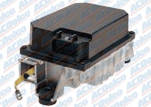
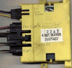
The problem was in the cruise control wiring. Unmentioned in KlingonFiero's original writeup is the requirement for a VSS buffer that takes the VSS signal and has an output to the cruise module. I had installed one of these and had forgotten it was in there.
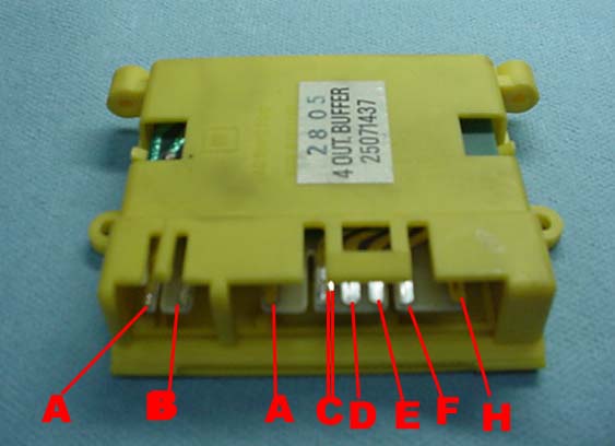
The connector that came with the unit had the wires A & B (Yellow/Purple) reversed. Purple is grounded in the speedo and is also in this VSS buffer. I reversed them in the connector to the VSS buffer. So the speedo now works. Haven't managed to get the cruise control working yet.
ive been having a hell of a time trying to get mine to work. i have all the wiring correct except for the vss wire. i tried using the 2kppm output from the speedometer that went to the original fiero cruise and couldnt get it to work. then i tried tapping into the yellow vss wire like his instructions said that should be 4kppm like needed, but when i tap into that wire my speedo stops working. clip the wire and the speedo works again. anybody know why that would happen? i have a 3800 with manual, so if i run cruise to the pcm, id never get it to work. the pcm reads 1/4 my actual speed and the cruise needs to see 30mph to engage. on my scanner it reads 20 mph at 75-80 mph
what is that buffer unit youre talking about? is that a stock part in an 84 or an aftmkt part?
[This message has been edited by Hurricane (edited 11-13-2007).]
if you look at the caprice schematic, youll see pins D & G are both open with brake pedal depressed, which means that both of those have power unless the brake pedal is activated which is contrary to what he says in his thread. secondly, he claimed to have hooked up the yellow wire to pick up his vss signal, which is the positive lead of the vss circuit. the purple wire is the pulsed ground which is what it needs to work as shown in the schematic.
now according to what he said and what the schematic shows, i simply dont understand how his cruise works. perhaps he cited the wrong make/model, i dont know
edit
i checked a schematic for a 93 caprice and it has pin g normally open and pin d normally closed. either they changed it or perhaps there was a mistake in the diagram my head is now spinning from all this studying of the diagrams, hopefully somebody else will have some input
i found out that you need to tap into the yellow vss wire, but for some reason if i tap into it up front it kills my speedometer, but if i tap in at the back by the trans then it still works and i can measure the signal at the cruise unit then. i hooked my drill up to the vss to make diagnosing easier. im at a complete loss here
[This message has been edited by Hurricane (edited 11-13-2007).]
IP: Logged
11:25 AM
Nov 14th, 2007
KlingonFiero Member
Posts: 1503 From: Littleton,Co USA Registered: Feb 2002
I would have sworn I had added the part about needing a VSS Amplifier for the Electronic CC unit.
I discovered it was needed to let the cc unit work more consistently.
I have also recently discovered that the speedometer/VSS wiring is DIFFERENT on different years.
I cannot recall which is which at the moment, but On eof the speedo's I have grounds the Yellow wire at the speedo and the other speedo grounds the purple wire...
Strange....
IP: Logged
11:03 AM
jscott1 Member
Posts: 21676 From: Houston, TX , USA Registered: Dec 2001
I have also recently discovered that the speedometer/VSS wiring is DIFFERENT on different years.
I cannot recall which is which at the moment, but On eof the speedo's I have grounds the Yellow wire at the speedo and the other speedo grounds the purple wire...
Strange....
If that's true, I have yet to see a speedometer with reversed wires (yellow to ground), and I've taken about 20 of them apart so far.
IP: Logged
11:22 AM
fierosound Member
Posts: 15258 From: Calgary, Canada Registered: Nov 1999
I have also recently discovered that the speedometer/VSS wiring is DIFFERENT on different years. I cannot recall which is which at the moment, but On eof the speedo's I have grounds the Yellow wire at the speedo and the other speedo grounds the purple wire...
That definitely seems to be the case. This is how the VSS buffer I used had the Yellow/Purple (top two) wires connected. OPPOSITE of what the diagram above showed. As I said, reversing them solved the problem and the speedo now works.
[This message has been edited by fierosound (edited 11-14-2007).]
IP: Logged
04:05 PM
PFF
System Bot
jscott1 Member
Posts: 21676 From: Houston, TX , USA Registered: Dec 2001
That definitely seems to be the case. This is how the VSS buffer I used had the Yellow/Purple (top two) wires connected. OPPOSITE of what the diagram above showed. As I said, reversing them solved the problem and the speedo now works.
Was that on an 84?? It wouldn't surprise me if the 84 was the oddball connections.
IP: Logged
05:12 PM
fierosound Member
Posts: 15258 From: Calgary, Canada Registered: Nov 1999
Was that on an 84?? It wouldn't surprise me if the 84 was the oddball connections.
No, no, no. None of the Fieros have this module in them. The 84's have a "buffer chip" in the speedo, later year Fieros have the cruise control module. This is the VSS buffer that is needed to make the electronic cruise control work according to KlingonFiero. You need it to get the correct pulse information for the electronic cruise module. I think only 92-94 GM's with electronic cruise had them and later years had the ECM doing the job of this VSS buffer which is why you won't find them in 95/96 and up GMs.
where would that module be located at usually? i guess ill have to get one this weekend
Under the dash on the driver's side, usually above the steering column, attached to the firewall. It's easy to spot now that you know what you're looking for (yellow or white, size of a cigarette pack). If it's a GM car between 92-94 with and electronic cruise under the hood, it SHOULD have one of these in it. It seems more "upper end" GMs have them, so look at full size cars like Roadmaster, Bonnevilles, Caprice etc.
IP: Logged
08:54 AM
Nov 16th, 2007
jscott1 Member
Posts: 21676 From: Houston, TX , USA Registered: Dec 2001
Well, it's starting to get warm enough to get out in the garage again (maybe). I'll have to think about taking another stab at getting this cruise control working. I have an 84, my friend has an 86. Neither of us has gotten it working and we've double checked everything against Darth's diagrams too http://dtcc.cz28.com/files/electcrz.zip
Beside KingonFiero, has nobody else had any success getting one of these things working??
IP: Logged
11:50 AM
Mar 29th, 2008
Fino Member
Posts: 813 From: St. Johns, MI. USA Registered: Jan 2002