Hi this simple question is for the electronics department.
I'm looking to install 2 LED setup in my Fiero, It's a direct connection to the power source (Parallel?) with 2 LEDs running direct. The LED I've got is:
5mm 2.2V @ 100mA
What resistor should I use for each LED ? According to this formula the result is 98ohm
Run the LED's in series, and the forward voltage drop is the sum of the individuals. The current is the same (100ma). That will let you use a smaller resistor that will make less heat.
For example - two 2.2V @100ma LED's in series = 4.4V @100ma. (14V-4.4V)/0.1A = 96 ohms
Originally posted by ryan.hess: Run the LED's in series, and the forward voltage drop is the sum of the individuals. The current is the same (100ma). That will let you use a smaller resistor that will make less heat. For example - two 2.2V @100ma LED's in series = 4.4V @100ma. (14V-4.4V)/0.1A = 96 ohms I^2*R = 0.amp1*0.1amp*96ohm = 0.96 watts dissipated
Thanks Ryan, Sorry 4 the newbie questions 1. So for automotive use we calculate a Source voltage of 14V? 2. Should I'll use the same "2W 100 ohm resistor. brown black brown." and connect them one to the other and then to the source? 2. Or Should it be an exact 96 ohm - White blue black? 3. If I would like to connect just a single LED do I use that same 100ohm resistor ?
Thanks again.
IP: Logged
06:09 PM
Marvin McInnis Member
Posts: 11599 From: ~ Kansas City, USA Registered: Apr 2002
Is that the "absolute maximum" rating of the LED, the "maximum continuous" rating, or the "typical operation" rating? As Ryan said, 100 ma is pretty high current for normal continuous (not pulsed) LED operation.
You should never use the "absolute maximum" or "maximum continuous" ratings in design, since these represent "do not exceed" values. Smoke often accompanies operation at or above "maximum continuous" conditions.
quote
1. So for automotive use we calculate a Source voltage of 14V? 2. Should I use the same ... resistor ... and connect them one to the other and then to the source? 2. Or Should it be an exact 96 ohm ... ? 3. If I would like to connect just a single LED do I use that same ... resistor ?
1. Yes. 14 volts is typical alternator output voltage.
2. Yes. Connect the resistor and the two LEDS all in series. Make sure that the cathode ends of both LEDs are oriented in the same electrical direction ... toward ground.
3. No. The exact resistance is far from critical, and 96 ohms is a non-standard value. Standard value resistors are much cheaper and much more widely available.
4. In this example using one LED vs. two LEDs in series, yes you could ... but I would suggest a resistance of at least 120 ohms (a standard value). With a 14 volt supply and a 120 ohm resistor, the operating current through one LED would be would be ~98 ma and the current through two LEDs in series would be ~80 ma.
[This message has been edited by Marvin McInnis (edited 12-17-2006).]
IP: Logged
06:33 PM
DrDave Member
Posts: 333 From: Port Angeles, Wa. U.S.A. Registered: May 2001
We almost always use 1k resistors 1/4 watt. Ya might increase the resistance to 1.4k for the green leds, don't have a feel for the blue leds. I'm assuming these are for inside the cabin, and not the new High intensity LEDs.
[This message has been edited by DrDave (edited 12-17-2006).]
IP: Logged
07:24 PM
DMaxME Member
Posts: 184 From: Rochester, NY Registered: Dec 2006
Just out of curiosity, where are you putting these LEDs? I ask because I was thinking about building some for the dash lights, to make all the warning lights actually bright and warning like, rather than dim and easily ignorable
IP: Logged
08:21 PM
Dec 18th, 2006
Mister Member
Posts: 1975 From: Calgary, Alberta, Canada Registered: Aug 2004
Originally posted by Marvin McInnis: 4. In this example using one LED vs. two LEDs in series, yes you could ... but I would suggest a resistance of at least 120 ohms (a standard value). With a 14 volt supply and a 120 ohm resistor, the operating current through one LED would be would be ~98 ma and the current through two LEDs in series would be ~80 ma.
Thanks a lot 4 the info (+)
quote
Originally posted by DrDave: We almost always use 1k resistors 1/4 watt. I'm assuming these are for inside the cabin, and not the new High intensity LEDs.
Thanks, So what happens if I'll use a 1K resistor? will it produce less light? I've got a few of those.
quote
Originally posted by DMaxME:Just out of curiosity, where are you putting these LEDs?
These will be out side the "Box", I promise to post when I have it running
IP: Logged
07:34 AM
Marvin McInnis Member
Posts: 11599 From: ~ Kansas City, USA Registered: Apr 2002
If you use a resistance value greater than 120 ohms, the light output of the LED will be reduced somewhat (higher resistance => less light) but it won't hurt anything.
Assuming a 14 volt supply voltage, for most LEDs I'd suggest starting with a 470 ohm resistor. (470 ohms is a standard value.) This will operate the circuit at about 20 ma and produce a surprising amount of light from the LED(s). Then you can experiment with higher or lower resistance values, all the way down to 120 ohms.
[This message has been edited by Marvin McInnis (edited 12-18-2006).]
IP: Logged
11:37 AM
Mister Member
Posts: 1975 From: Calgary, Alberta, Canada Registered: Aug 2004
to make all the warning lights actually bright and warning like, rather than dim and easily ignorable
Thanks I got a chuckle out of this quote.
The stock Fiero cluster is the dimmest thing I have ever seen. Especially the side lit ones. The firebird cluster is very bright and uses LEDs for the warning lights.
IP: Logged
02:17 PM
TrotFox Member
Posts: 138 From: Carrollton, TX USA Registered: Feb 2005
You know you've gotta post pix when you're done, right? This is another project I've wanted to do for years but never gotten around to. Too many other hobbies. ; ]
Actually, I expect to eventually have LEDs in every illuminated spot on the car with the exception of the headlights. I've done one 3rd brake light which is currently in the car...
This is not the way to do it though! I built this years ago before LEDs were really bright enough to get the job done so to make as much light as the stock bulb I blanketed the lens with 105 5mm red superbright LEDs from RadioShack (5000 MCD?) They are arranged in groups of 6 with a 100 Ohm resistor for each series group. It works but it's not in any way elegant.
Red 5spd Formula Trot, the dim, fox...
(edited for 3rd light photo)
[This message has been edited by TrotFox (edited 12-18-2006).]
IP: Logged
09:32 PM
PFF
System Bot
jscott1 Member
Posts: 21676 From: Houston, TX , USA Registered: Dec 2001
Good gracious! You're right, that is not the way to do it.
*chuckle* My current plans are split between doing what Acura did with the twin'd diffracted 10mm LEDs (this is a guess based on observations from the road) and wimping out with the 3W Luxeon units from theledlight.com/ I've all but given up on the indirect lighting idea I was considering for the rear running lights...
I've also had in mind for a number of years to recreate the 'Pontiac' emblem on the rear fascia out of clear material with red EL wire backlighting. I found a company that makes resin molding kits and has clear resin for use in them. I just haven't spent the money on it yet because there's always something that needs fixing. : ]
Red 5spd Formula Trot, the gray, fox...
IP: Logged
04:38 AM
Mister Member
Posts: 1975 From: Calgary, Alberta, Canada Registered: Aug 2004
Originally posted by TrotFox: I've also had in mind for a number of years to recreate the 'Pontiac' emblem on the rear fascia out of clear material with red EL wire backlighting. I found a company that makes resin molding kits and has clear resin for use in them. I just haven't spent the money on it yet because there's always something that needs fixing. : ] Red 5spd Formula Trot, the gray, fox...
Good one TrotFox, I had my mind on a similar idea for a while now...But there's always the chance it's just going to look amateurishly and cheap which I can't except...Gotta come up with a really good looking surface finish.
As for this little LED project of mine, it's so simple it hurts LOL Will post results soon�
IP: Logged
07:50 AM
TrotFox Member
Posts: 138 From: Carrollton, TX USA Registered: Feb 2005
I have a brand-new from the dealer (still in the wrapper) Pontiac emblem just waiting to be used for mold making for the lit emblem project. I'm real good about gathering half the parts I need for something and then forgetting about it for years. Damned ADD! } ; ]
Red 5spd Formula (neglected) Trot, the many-hobbied, fox...
IP: Logged
11:46 PM
Mar 5th, 2007
Mister Member
Posts: 1975 From: Calgary, Alberta, Canada Registered: Aug 2004
Hi all, I need to revive this old question thread cause there is a new project cooking
Thanks to Fieromaniac, I've read the LED Circuitry Tutorial - http://www.theledlight.com/ledcircuits.html And have a good understanding of how things work, but I always like your input to make sure I'm getting the best out of it, and don't mess it up.
I've got a setup of LEDs to be used for backup light, mounting surface is limited.
I'm using:
- 8 LEDs
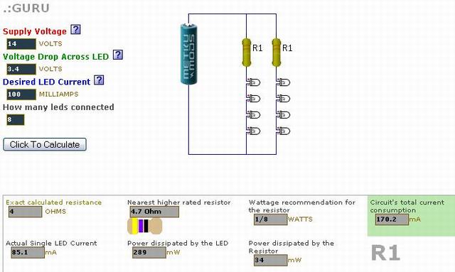
LED Specs as printed on package sticker: 10mm 0.5w Iv - 280,000 mcd Vf - 3.6-4.0 V (on eBay it said 3.4V) Current - 100ma
From the eBay page: * Reverse Voltage: 5.0 V * DC Forward Voltage: Typical: 3.4 V Max: 3.8 V * Luminous Intensity MCD: Typ: 280,000 mcd * DC Forward Current: 100mA * Viewing Angle: 40±5degree * Lead Soldering Temp: 260oC for 5 seconds
Using the Current Limiting Resistor Calculator for Leds here: http://ledcalc.com/#calc It gave me a few options for wiring, the easiest looks like a series connection of 4 and 4 with a 4.7 Ohm resistor.
Questions:
1. These are for back-up light (will be used maybe 20-30 seconds once a day) but I need it to be as BRIGHT as possible. I would like to wire them at peak performance. Do I get the max light output with the above connection method and resistor?
2. Do I really need such a small resistor or can I just hook it up direct to the Car's voltage supply?
3. Is it O.K to bend the LED's leads, cut and solder them together like in this pic from Fieromaniac? (The 10mm leads are thicker)
4. If not, What wire do I need to connect between the LEDs?
5. Since these won't be ON when I start the car, do you think I need to use some sort of power source stabilizer like Fieromaniac did?
quote
Originally posted by Fieromaniac: i will install stabilized powersources for every cirquit to save the LED from powerspikes of the starter
6. Did I miss anything ?
Thanks for your input.
[This message has been edited by Mister (edited 05-18-2008).]
IP: Logged
04:33 PM
Marvin McInnis Member
Posts: 11599 From: ~ Kansas City, USA Registered: Apr 2002
1. Do I get the max light output with the above connection method and resistor?
2. Do I really need such a small resistor or can I just hook it up direct to the Car's voltage supply?
3. Is it O.K to bend the LED's leads, cut and solder them together ... ?
4. If not, What wire do I need to connect between the LEDs?
5. Since these won't be ON when I start the car, do you think I need to use some sort of power source stabilizer ... ?
1. Yes, assuming simple DC operation.
2. YES! The resistor is needed to limit the current through the LEDs to a safe value. Without a resistor, you will definitely let the smoke out of the LEDs.
3, 4. Yes. Be careful, though. The proper technique is always to grip the lead firmly with needle nose pliers between the LED body and the point of the bend.
5. Probably not. Besides limiting the operating current, the resistor provides a small measure of spike protection already. If it were me, I would probably include a power diode (such as a member of the 1N4001 family) in parallel with each LED string to provide reverse-voltage spike protection. The cathode end of each diode (the end marked with the band) should connect at the junction between a resistor and the topmost LED, and the anode end of each diode should go to ground.
While you didn't ask, I would strongly suggest that you start with a design current of 50 ma rather than 100 ma, and only increase it if you need a lot more light. It's seldom a good idea to design using the published maximum specs for semiconductor devices.
[This message has been edited by Marvin McInnis (edited 05-18-2008).]
IP: Logged
07:04 PM
Mister Member
Posts: 1975 From: Calgary, Alberta, Canada Registered: Aug 2004
Hey Marvin and thank you, that answered most of the questions BTW - Since you responded earlier on this thread I already have you rated with a (+) Thanks again for your help.
~~
quote
Originally posted by Marvin McInnis: I would strongly suggest that you start with a design current of 50 ma rather than 100 ma, and only increase it if you need a lot more light. It's seldom a good idea to design using the published maximum specs for semiconductor devices.
With the current design @ 100mA and a 4.7 Ω the Actual Single LED Current is 85.1mA which is below max specs of 100mA (On the eBay page they advertise Peak Forward Current at 120 mA)
1A. Do you think it would be a problem operating it at this rate? I don't think one could have enough back-up light
2A. Should I use 1/4w or 1/8 resistor? 2 online calculators say different things.
[This message has been edited by Mister (edited 05-18-2008).]
IP: Logged
07:29 PM
Marvin McInnis Member
Posts: 11599 From: ~ Kansas City, USA Registered: Apr 2002
1A. Do you think it would be a problem operating it at this rate?
2A. Should I use 1/4w or 1/8 resistor? 2 online calculators say different things.
1A. Unfortunately, it's not just a matter of staying below the rated current, it's also a matter of heat dissipation. At 85 ma, each LED will have to dissipate about 0.3 watts as heat. That doesn't sound like much, but the LED package may not be able to dissipate that much heat (without an external heat sink) and still keep the junction temperature below 200 C, where most silicon-based semiconductor devices begin to fail. Compounding the problem, I think the light output of most LEDs drops off somewhat with increasing junction temperature.
2A. At 4.7 ohms and 85 ma, the power dissipation in each resistor will be about 0.034 watts (P = I2 * R), so any resistor rating higher than that will be OK. I would choose 1/4 watt resistors for this application, though, because they are more widely available, cheaper, and more rugged mechanically than 1/8 watt resistors.
[This message has been edited by Marvin McInnis (edited 05-20-2008).]
IP: Logged
11:08 PM
Mister Member
Posts: 1975 From: Calgary, Alberta, Canada Registered: Aug 2004
So when you say "experiment" from 50mA and up how do I know when it's getting to hot for the LED? Is there a magic number for max brightness with no excessive heat? (once again these would operate in very short intervals)
Thanks Marvin
IP: Logged
11:14 PM
PFF
System Bot
May 19th, 2008
Robert 2 Member
Posts: 2401 From: St Hubert Quebec Canada Registered: Jan 2006
So when you say "experiment" from 50mA and up how do I know when it's getting to hot for the LED? Is there a magic number for max brightness with no excessive heat? (once again these would operate in very short intervals)
Thanks
IP: Logged
11:02 AM
Marvin McInnis Member
Posts: 11599 From: ~ Kansas City, USA Registered: Apr 2002
when you say "experiment" from 50mA and up how do I know when it's getting to hot for the LED?
"Experiment" means just that, and you're likely to kill some of your LEDs along the way. (The fancy name for this is "destructive testing.") The LEDs will reach a stable operating temperature after only a second or two of operation, and you may be able to measure temperature with a simple infrared (non-contact) thermometer. If the LEDs ever get too hot to touch, then they are almost certainly running too hot internally.
quote
Is there a magic number for max brightness with no excessive heat?
No. All design is a series of tradeoffs. Some manufacturers' data sheets do include thermal data for various LED power levels, ambient temperatures, and mounting configurations. I would ask your vendor if they can provide this information.
You might also want to consider what happens as the supply voltage varies throughout its normal range. In the circuit you posted above, four 3.4 volt LEDs in series will work fine at 14 volts but they won't work as expected (and produce no light at all) when the system voltage drops below 13.6 volts. To use those LEDs in a car, I think that a maximum of three of them in series, with a necessarily higher value resistor, would be a much better design choice. An even better, if slightly more complex, solution would be to replace the single current limiting resistor with a constant-current source; this would require at least two resistors and two inexpensive transistors.
[This message has been edited by Marvin McInnis (edited 05-20-2008).]
IP: Logged
04:06 PM
Mister Member
Posts: 1975 From: Calgary, Alberta, Canada Registered: Aug 2004


 this simple question is for the electronics department.