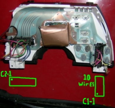
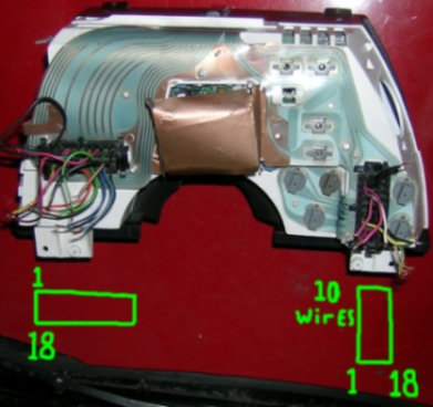
Unfortunately, it appears that the connectors will fit in Either hole in any position. Can anyone tell me if the way I have indicated below is the correct position ?
ALSO - is the gold paper (square) folded across the back just a protector or something else ?
[This message has been edited by PaulJK (edited 08-17-2007).]
IP: Logged
04:10 AM
PFF
System Bot
jscott1 Member
Posts: 21676 From: Houston, TX , USA Registered: Dec 2001
C1-1 Ign Power Pnk/Blk C1-2 SES Light Brn/white C1-3 Seatbelt light (power for 5 secs) Yellow C1-4 Ground/blk C1-5 Shift light ?????? C1-6 Not Used C1-7 Tach Imput Wht C1-8 Ign Power from fuse Pnk/blk C1-9 Ground/blk C1-10 Speed sig. Out to ecm C1-11 Speed sig. Out to cruise C1-12 Not Used C1-13 Not Used C1-14 Not Used C1-15 Not Used C1-16 Brake Light Tan/Wht C1-17 Low Collant (Not used on the fiero) C1-18 Ign Power from fuse Pnk/Blk
C2-1 Ground/Blk C2-2 Ground/Blk C2-3 Ign Power Pnk/Blk C2-4 Ign Power Pnk/Blk C2-5 Collant Temp Drk/Grn C2-6 Oil Pressure Tan C2-7 Fuel guage Pink C2-8 Outside Temp Tan C2-9 VSS Gound Blk C2-10 Dim Display BRN C2-11 LH Turn Lt Blue C2-12 RH Turn Drk Blue C2-13 High Beam Lt Grn C2-14 Illumion Battery voltage Gray ????? C2-15 Battery Power from fuse (Controls Trip) C2-16 Not Used C2-17 Not Used C2-18 VSS Imput Yellow http://home.comcast.net/~fiero_addict/index.htm
[This message has been edited by ig88vsbobafett (edited 08-17-2007).]
IP: Logged
03:57 PM
PaulJK Member
Posts: 6638 From: Los Angeles Registered: Oct 2001
Jon, yep, i'm surprised that these connectors will fit in any way you want to put them in. I looked ta the wires in the connectors and the traces on the mylar and got to this point by trying to match them up. Strange thing is that there are wires that don't line up to traces, no matter what you do . I was just looking for verification before I put the power to it .
ig88 - thanks; i guess i can figure out C1 and C2 from the wire colors, but i still won't know which connector goes into which hole.
[This message has been edited by PaulJK (edited 08-17-2007).]
IP: Logged
04:59 PM
ig88vsbobafett Member
Posts: 3446 From: Cheyenne Wyoming Registered: Oct 2001
Thanks very much for your input ... i will be working on this more tonight. (i just finished the S10 brake booster upgrade and had to re-wire my brake light sockets (OEM ferrari) because they were shorting out the wires and blowing the fuse - PS if you have a choice of parts, buy japanese parts NOT italian )
IP: Logged
12:53 AM
sjmaye Member
Posts: 2468 From: Hendersonville, TN USA Registered: Jun 2003
After studying the tracing and wires coming from the connectors, i decided that the configuraration shown above is correct.
The connector on the left in the pic has (3) black wires followed by (3) pink wires across the top starting left and moving right (positions 1,2,3 4). ONLY the wide traces in that spot woud keep all the blacks together and all the pinks together - in any other position (or with the other connector) different color wires would short on the wide traces in this spot. So i concluded that this connector in this position MUST be correct.
Assuming that all the WIRES must meet a trace (but NOT all the traces have to be used), the way shown for the connector on the right is the only way THAT works. If you turn this connector and insert it, there are wires that meet no trace.
Feeling confident, i twisted the pinks together, twisted the blacks together and used wires with alligator clips to connect the pinks (power) and blacks (grounds) to the car battery. YEP, the dash lit up and the CHECK GAGES light came on for a few seconds then went out.
I didn't keep it lit too long because none of the other connections were made, but i did verify that the speedo showed "0", odometer and trip features were working, and successfully switched between english and metric units
[This message has been edited by PaulJK (edited 08-20-2007).]
IP: Logged
08:35 AM
PaulJK Member
Posts: 6638 From: Los Angeles Registered: Oct 2001
ig88 - thank you for posting the info. Using your chart and the pic, the connector on the right is C1 and the connector on the left is C2. The C2-18 yellow wire is in position 18 in the lower left .
IP: Logged
09:33 AM
Daviero Member
Posts: 382 From: Thunder Bay, ON Canada Registered: Jan 2006
Very interesting alternative. How are you mounting this in your dash - do you have a stock, custom or Cavalier dash? Any pictures of this aspect of your project? Thanks, Dave
------------------ Daviero - 88 N* GT
IP: Logged
09:48 AM
ig88vsbobafett Member
Posts: 3446 From: Cheyenne Wyoming Registered: Oct 2001
daviero - it took a dremel tool, carpet knife and a few hours, but i modified the fiero dash pod to accommodate the cavalier instrument. it's not hard just tedious and dusty . rather than screw, i think i'm just gonna epoxy it together after i verify that everything is working properly.
ig88 - thanks for the link. i just re-read the thread. looks like the (2) wires for the temp sensor are still unknown - at least no one posted how the outside temp sensor hooked up . Do you know if one wire is from the digital dash to the sensor and the other from the sensor to ground ?
Can you go back into your posts and fix the pics ? a LOT of them just show as a white box with red X .... (maybe they just need re-sized smaller)
[This message has been edited by PaulJK (edited 08-20-2007).]
IP: Logged
02:31 PM
jscott1 Member
Posts: 21676 From: Houston, TX , USA Registered: Dec 2001
The connector on the left in the pic has (3) black wires followed by (3) pink wires across the top starting left and moving right (positions 1,2,3 4). ONLY the wide traces in that spot woud keep all the blacks together and all the pinks together - in any other position (or with the other connector) different color wires would short on the wide traces in this spot. So i concluded that this connector in this position MUST be correct.
That was what I suggested earlier, you could match the populated wires to the copper traces...
Does anyone know why these clusters have multiple power and grounds? Every cluster I have looked at has at least 3 power wires and at least 2 grounds. At first I thought it was just lazy designers from the 80s but even the more modern ones from the 90s are just as bad.
IP: Logged
04:26 PM
Aug 24th, 2007
PaulJK Member
Posts: 6638 From: Los Angeles Registered: Oct 2001
as always, thanks for the good advice, Jon. When i installed gauges in my kitcar, the manufacturer recommended giving each one its own seperate ground - i think this prevents some kind of electrical feedback from one gauge to another. ... don't know about power though; maybe the same idea ....
[This message has been edited by PaulJK (edited 08-24-2007).]
IP: Logged
02:55 AM
sjmaye Member
Posts: 2468 From: Hendersonville, TN USA Registered: Jun 2003
This is a dumb question, but bear with me. The cavalier housing is noticably curved in comparison to the Fiero. Are you taking the gauge guts out out of the Cavalier housing and putting them in the Fiero housing?
IP: Logged
03:57 AM
PaulJK Member
Posts: 6638 From: Los Angeles Registered: Oct 2001
No, i am mounting the cavalier instrument cluster shown in the very first pic into the fiero pod. I removed the fiero instrument panel (with speedo and tach) and then dremelled the remaining pod enclosure to accommodate the cavalier piece you see in the pic. The top of the cavalier piece is flat across the top so it mates up fine, but the places on the fiero enclosure where the dimmer switch and defroster button are mounted needed to be trimmed out for the curved sides of the cavalier piece to fit.
[This message has been edited by PaulJK (edited 08-24-2007).]


 . I was just looking for verification before I put the power to it
  .
. )
)