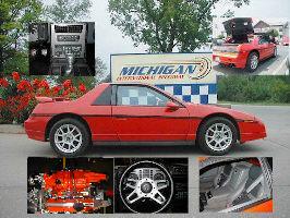
to answer some questions in another thread, i thought id start my own with answers to a few questions that i couldnt find before doing it on my own. ill show some of the things ive done to swap in a 3800 into my 86 gt. just got the transmission rebuilt and trying to do a very thorough job on the install because my wife and i are planning a route 66 trip in this car once its finished. so if you see anything that needs to be addressed, please speak up.
****** this low mount is a design of loydes from fastfieros.com his site had the only pics of this alternator that i could find, so all credit goes to him, i simply copied what i saw there
**********
low mount alternator with new style from 02 gtp-
youll need a 10mm spacer between the alt and the aluminum dogbone bracket, on the lower left hole the support bracket i made with 1/8" steel plate and part of the original support bracket for the gtp alt. i bolted it to where the power steering pump originally was. i machined the dog bone bracket down to line up the idler pulley to the alt and crankshaft. the tensioner is off a mid 90's taurus. the pulleys are within 1 mm alignment. after machining, i cut & welded 1/4" aluminum plate to reinforce the bracket which was significantly weakened by removing enough material to mount the tensioner
*******some more info********** dogbone bracket is machined to 25mm thickness, just enough to allow the tensioner to sit flat and not move. i used a machinist vise in a drill press with a burr to remove just a little at a time until i got a perfect fit, it also leaves it much more uniform and flat than doing it by hand.
tensioner is auto zone #353967, i believe its a dayton #305217
the belt youll need if you keep the ac like i did is a gates K060790, 20mmx2018mm i had to buy 4 different belts before i found one that fit nice, this one is perfect on my setup
i used 4 washers, that were a total of 10mm thick between the alternator and the dogbone bracket. i recommend you do something similar to what i did once you machine the dogbone bracket down. theres a significant amount removed from the gussets, so reinforce now or fix later.
boost bypass valve and thermostat neck -
ive seen lots of people saying that you cant run a fiero thermostat housing AND the boost bypass valve. since i think the valve was put there for some good reason, by somebody who is a lot smarter than me, i figured i would leave it there. after modifying the thermostat neck, the vacuum nipple on the boost bypass would be touching it. i ground off the plastic rivets underneath and rotated the valve so they wouldnt interfere. i then used a small screw in place of each plastic rivet and added a dab of rtv over the top to keep them from backing out. you have to be careful you dont run them in very far at all, or else youll puncture the valve. you only get about 1/8" into the remainder of the rivet
4 speed shift cable clearance -
my issue here was two fold, first i had zero clearance for one of the shift cables, and secondly, i dont like how most 3800 exhausts are run. i needed to have a cat and a full size muffler because of emissions testing, and didnt like the idea of those 2 being crammed in between the engine and trunk (which i didnt want to cut either).
so what i did was take a page from PBJ's play book and make a crossover pipe that would dip down to give me clearance for the shift cable and exit towards the front of the car so that i could run a stock style exhaust. i used 2" j bends from summit to make the crossover and ran 2.5" exhaust the rest of the way. i also relocated the 02 sensor so that it would get the correct reading for both cylinder banks. plugged up the old sensor location and welded some plate to a flange that bolted in the stock exhaust location so that i would have that option down the road if i needed it. i cut off the spring retainers form the old exhaust and welded them to the new so that it would mount in the same fashion as before
[This message has been edited by Hurricane (edited 04-26-2007).]
IP: Logged
08:45 PM
PFF
System Bot
darkhorizon Member
Posts: 12279 From: Flint Michigan Registered: Jan 2006
I think that exhaust looks quite restrictive. Even going to a 3 inch exhaust in the gtp's people are seeing anywhere from 10-15HP, along with it being supportive of more boost, which = horsepower. I think your on the right track with the rear exhaust, by running the 2inch cross over and such, but having it splice into a 2.5, all while going through a very tight almost 180 degree bend is just a scary thought. If this was N/A, or a modded 3800 with a 3.8 pulley I dont think it would matter so much, but if your just going to leave everything stock, or god forbid mod with this exhaust I would monitor it closely.
I love the therm housing, youll thank yourself for doing that. And its great that somone finally attempted the "fiero esk" exhaust on a 3800, but I think you should look into a mustang header for the rear, and some 3inch components if you ever plan on seeing some extra power out of this 3800.
its a completely stock engine and it will remain that way. do you still think that its an issue? i dont plan on doing anything to this except drive it and put gas in it
after looking at club gp, it seems as though the stock exhaust is far more restrictive than mine is. other than that 180 at the manifold, everything else is free flowing 2.5 mandrel bends.
the stock gp has this, which is less than 2" diameter and a 2.25" downpipe
im not looking for maximum power. stock performance is fine by me, but at the same time i dont want to cause any kr issues. let me know what you think
Ok, I was just warning you that we have plenty of problems with things like that ubend and such, if your staying really stock, then it shouldnt be a problem.
Not that I want to discourage you even more, but my friends 4speed swap just shattered 3rd gear 2 days ago.
Ok, I was just warning you that we have plenty of problems with things like that ubend and such, if your staying really stock, then it shouldnt be a problem.
Not that I want to discourage you even more, but my friends 4speed swap just shattered 3rd gear 2 days ago.
thats a big part of why im staying stock too. i had the trans rebuilt when i pulled the 2.8 did your friend abuse his or what? i really dont want to have to convert to a auto, but if i blow the tranny thats what ill end up doing unless the 6 speed proves to be more reliable
IP: Logged
07:39 AM
p8ntman442 Member
Posts: 1747 From: portsmouth RI Registered: Sep 2003
While its out, remove your clutch arm and replace it with the cast iron one. Or weld the **** out of that one to make it strong. That will be a first point of failure on your swap, especially if your running an upgraded clutch.
IP: Logged
11:29 AM
darkhorizon Member
Posts: 12279 From: Flint Michigan Registered: Jan 2006
I agree with the clutch arm suggestion, at least replace it and put new bearings in as it is a failure point.
As far as the transmission, he was at the track.. but he is fairly hard on it, so I would imagine that if you were to be overly paranoid about it, you could possibly not have to many problems. But if you get some go fast bugs, which I wouldnt doubt most people get driving this setup, then you might tend to forget some time. IMO, the manual just isnt at all ready to handle this motor, not so much for the horsepower, but honestly its just the low end torque that competes with even the stoutest v8 swaps, and we all know they have problems with this too. These transmissions worked just fine with the hampster in wheel motors that they came with, but its a whole different story when you are more than doubleing the torque these were designed for, and trippleing the torque that the hampster wheel stock motors put out.
can anybody tell me what i need to do to get the gtp ac compressor to function? it has a 3 wire switch needed to run to the pcm, but it doesnt have any sensors on the compressor like the fiero had. also, im trying to wire my c203 and none of the pins /colotrs match up to any pinouts ive seen. for instance, slot A doesnt even have a wire in it, when most things say it should be the upshift lamp, which i have and was working fine before i pulled the motor
IP: Logged
11:11 PM
darkhorizon Member
Posts: 12279 From: Flint Michigan Registered: Jan 2006
I wire in a new A/C clucth relay and have it fed by the blue wire on the C203 pin D this is +12volts that has gone through the Fiero's stock pressure sensors so there is no need to use the GTP sensors at the compressor. basically the black wire from C203 pin N is the power that the relay will switch to feed the clutch solenoid. So on the newer relays pin 86 is ground pin 85 is connected to C203 pin D pin 30 is connected to C203 pin N and pin 87 connects to the green wire going to the A/C clutch relay. Also do not forget to include the clutch solenoid diode that is used in the A/C cars. Dan
I wire in a new A/C clucth relay and have it fed by the blue wire on the C203 pin D this is +12volts that has gone through the Fiero's stock pressure sensors so there is no need to use the GTP sensors at the compressor. basically the black wire from C203 pin N is the power that the relay will switch to feed the clutch solenoid. So on the newer relays pin 86 is ground pin 85 is connected to C203 pin D pin 30 is connected to C203 pin N and pin 87 connects to the green wire going to the A/C clutch relay. Also do not forget to include the clutch solenoid diode that is used in the A/C cars. Dan
so do i still send any wires to the pcm? i thought the blue wire should go to pcm 22. im doing obd2 if that matters.
IP: Logged
10:46 AM
darkhorizon Member
Posts: 12279 From: Flint Michigan Registered: Jan 2006
If I remember correctly, the pcm wants to know when the ac is going to turn on so it can raise the idle, so it is basicly ran through it like a sensor to know when the body is going to turn on the ac.
IP: Logged
12:39 PM
ohio86se Member
Posts: 1308 From: akron, ohio, summit Registered: Mar 2002
Hey could you please give some more info and pics on the alt bracket that looks real good and I need to make one for mine still. Info on the machining of the dogbone bracket and then the lower mount it looks good!
well how much did you machine off the dog bone mount. do you have a part number to that tensioner? and any spacers or bolts used to make the alt and idler line up right?
ok here it is. took a few trips to the garage to find all the stuff.
dogbone bracket is machined to 25mm thickness, just enough to allow the tensioner to sit flat and not move. i used a machinist vise in a drill press with a burr to remove just a little at a time until i got a perfect fit, it also leaves i much more uniform and flat than doing it by hand.
tensioner is auto zone #353967, i believe its a dayton #305217
the belt youll need if you keep the ac like i did is a gates K060790, 20mmx2018mm i had to buy 4 different belts before i found one that fit nice, this one is perfect on my setup
i used 4 washers, that were a total of 10mm thick between the alternator and the dogbone bracket. i recommend you do something similar to what i did once you machine the dogbone bracket down. theres a significant amount removed from the gussets, so reinforce now or fix later.
any more questions just ask, i wish i had found that info before i did mine, would have made it much simpler
IP: Logged
08:44 PM
FIERO1985 Member
Posts: 801 From: Columbus Oh, USA Registered: Nov 2000
Ok thanks so much. the only question I have is I am having the plate machined for the alt mount and all I need to do is have it machined to a thickness of 25mm? that allows for the tensioner to line up with the rest of the pulleys? and also how do you know where to drill the hole for the pin on the tensioner to poke through?
can you post a picture of the alternator bracket, without the tensioner attached, I think that's what these guys are looking for, I'd like to see a picture of the whole setup done, with the alt and belt installed a bit father out so you can see the belt routing etc...
Ok thanks so much. the only question I have is I am having the plate machined for the alt mount and all I need to do is have it machined to a thickness of 25mm? that allows for the tensioner to line up with the rest of the pulleys? and also how do you know where to drill the hole for the pin on the tensioner to poke through?
Thanks a bunch +1 for sure
Dan
my bracket is 25mm thick where the tensioner mounts. take off only enough to get it to sit flat. there is no need to drill a hole for the pin, there is already a notch in between the gussets that the pin fits into once its been machined down so the tensioner wont move. youll see what i mean when you do it.
if you use the same tensioner that i did, all the pulleys will be in alignment. the first thing i did was align the alt to the crank, thats where i came up with the 10mm spacer. then i machined off a small amount off the bracket at a time until the tensioner lined up with the alt. i got them both within 1mm.
id recommend doing yours in the same order i did mine to be sure everything ends up in alignment
IP: Logged
06:51 AM
Apr 28th, 2007
FieroGTguy Member
Posts: 3087 From: Indianapolis , IN Registered: Mar 2001
well i got the engine installed last weekend and got everything hooked up this weekend. just tried to start and it would not fire. fuel pump is kicking on, didnt get a chance to check spark. i plugged my scanner in and it said "can not link", so i guess ill start there and make sure the pcm is getting power and those wires are correct.


.jpg)
.jpg)

.jpg)

.jpg)
.jpg)
.jpg)


.JPG)
.JPG)
.JPG)
.JPG)
.JPG)