Pennock's Fiero Forum
  Technical Discussion & Questions - Archive
  problem with charging system on my 4.9

T H I S   I S   A N   A R C H I V E D   T O P I C
  

Email This Page to Someone! | Printable Version


problem with charging system on my 4.9 by wiccantoy
Started on: 03-31-2007 09:22 PM
Replies: 19
Last post by: MaxCubes on 04-04-2007 09:33 PM
wiccantoy
Member
Posts: 3372
From: northwales , pa / Williamstown nj
Registered: Mar 2002


Feedback score:    (9)
Leave feedback


Total ratings: 90
Rate this member

Report this Post03-31-2007 09:22 PM Click Here to See the Profile for wiccantoySend a Private Message to wiccantoyDirect Link to This Post
cant seem to figure this one out . alternator isnt charging my battery. i charge the battery over night and come out and start the car and things ar efine till i drive for about 5 minutes when the voltage starts to drop. ive had the alt. tested and they said it is good....wtf? i put a volt meter on the alt when it is running and it only shows the voltage on the battery and you can slowly watch it drop as it runs for a while. now if the parts store can verify the alt works why cant i see it working in the car? im confused about this one

------------------

DONE: 86gt 5 speed 4.9 complete rebuild with buds outback northstar pistons , delta cams E303 cam , full ported , polished , stronger head springs, and flow tested heads and manifolds. rockcrawl's custom chip , polished crank . too much to list

88 coupe t-top #656 1 of only 339 base coupes made
85 t-top
87gt parts car
86 and 87 fiero database www.geocities.com/cwandall/fiero.html

IP: Logged
PFF
System Bot
86soon3.4
Member
Posts: 1537
From: Sobieski,WI,USA
Registered: Dec 2005


Feedback score:    (15)
Leave feedback

Rate this member

Report this Post03-31-2007 09:42 PM Click Here to See the Profile for 86soon3.4Send a Private Message to 86soon3.4Direct Link to This Post
Run a jumper wire (8 or 10 gage) from alternator hot terminal direct to the battery and then check if it is charging.
If it charges you have a wire broken or missing from the alternator to battery.

Steve
IP: Logged
wiccantoy
Member
Posts: 3372
From: northwales , pa / Williamstown nj
Registered: Mar 2002


Feedback score:    (9)
Leave feedback


Total ratings: 90
Rate this member

Report this Post03-31-2007 09:52 PM Click Here to See the Profile for wiccantoySend a Private Message to wiccantoyDirect Link to This Post
thats what i dont understand. there are only 2 wires on the alt. the main red one and a small brown one. when i put the volt meter to the red one i can read the voltage on the battery, so that one must be connected. the other one im not sure about
IP: Logged
Cooter
Member
Posts: 6328
From: Alabama, USA
Registered: Jun 99


Feedback score:    (11)
Leave feedback


Total ratings: 138
Rate this member

Report this Post03-31-2007 10:34 PM Click Here to See the Profile for CooterSend a Private Message to CooterDirect Link to This Post
You need to add a 'pull up resister' into the brown wire to supply enough voltage to excite the regulator enough for it to start charging. The regulator gets its power through the dash bulb and for the Caddy alternator, it may/may not be enough. I tapped into one of the 12v injector feeds, added a resister (I think 300~500 ohm- it has been a while) and connected it to the brown wire. The 'no-charge' light on the dash still works and the extra current through the resister is enough to run the alternator.
IP: Logged
wiccantoy
Member
Posts: 3372
From: northwales , pa / Williamstown nj
Registered: Mar 2002


Feedback score:    (9)
Leave feedback


Total ratings: 90
Rate this member

Report this Post03-31-2007 10:49 PM Click Here to See the Profile for wiccantoySend a Private Message to wiccantoyDirect Link to This Post
 
quote
Originally posted by Cooter:

You need to add a 'pull up resister' into the brown wire to supply enough voltage to excite the regulator enough for it to start charging. The regulator gets its power through the dash bulb and for the Caddy alternator, it may/may not be enough. I tapped into one of the 12v injector feeds, added a resister (I think 300~500 ohm- it has been a while) and connected it to the brown wire. The 'no-charge' light on the dash still works and the extra current through the resister is enough to run the alternator.


thats where i am having a problem understanding. this swap isnt new only the mods are new. it all worked fine before the mods now i need help finding out where it has failed to alow the alt to charge
IP: Logged
wiccantoy
Member
Posts: 3372
From: northwales , pa / Williamstown nj
Registered: Mar 2002


Feedback score:    (9)
Leave feedback


Total ratings: 90
Rate this member

Report this Post04-01-2007 10:27 AM Click Here to See the Profile for wiccantoySend a Private Message to wiccantoyDirect Link to This Post
i did look at it today. brown wire seems to have no breaks in it but i didnt run power through it to check it. red wire has a inline fuse on it .... now if that is bad will i still be able to read power through the wire from the battery to the alt? and does the computer have anything to do with the charging of the battery? reason i ask i just had the chip reprogramed.
IP: Logged
MaxCubes
Member
Posts: 693
From: El Paso, TX
Registered: Aug 2004


Feedback score: N/A
Leave feedback

Rate this member

Report this Post04-01-2007 10:59 PM Click Here to See the Profile for MaxCubesSend a Private Message to MaxCubesDirect Link to This Post
Bump!............I am having the same problem!....... Alternator not charging! I took it to Autozone to get tested and they said it is good. I had the brown wire connected to positive but it doesn't charge. Now I have a light bulb spliced in but it still doesn't charge!

..... exactly what ohm resistor must be used to make this alternator charge!?!?!?!?
IP: Logged
DrDave
Member
Posts: 333
From: Port Angeles, Wa. U.S.A.
Registered: May 2001


Feedback score: N/A
Leave feedback

Rate this member

Report this Post04-01-2007 11:30 PM Click Here to See the Profile for DrDaveSend a Private Message to DrDaveDirect Link to This Post
used to be there was a bulb that provided the voltage drop.
IP: Logged
GT
Member
Posts: 911
From: Silver Spring, MD USA
Registered: May 2003


Feedback score: N/A
Leave feedback

Rate this member

Report this Post04-02-2007 08:09 AM Click Here to See the Profile for GTSend a Private Message to GTDirect Link to This Post
I had the same problem. I can only suggest you try a new battery. If the alternator isn't getting enough voltage to turn on it won't charge. I don't remember exactly the voltage, but if the alternator is not sensing that the battery has somewhere around 12.1-12.5vdc or sometimes higher it won't charge. So if you have a dead cell, you may be able to charge the battery to 12.0 or a little higher, but it may not be as much as a new battery which is around 13 or so vdc. That is all I can suggest other than doing what I did and getting a single wire alternator like they use on race cars (and a new battery) which bypasses the whole brown wire circuit but then you don't get the battery light. Make sure you check the RESISTANCE of the B+ red wire coming from the alternator to the junction block. Mine looked like it was connected but the copper wasn't touching the connector internally so the alternator wasn't seeing battery voltage and wouldn't charge.

Good luck with it.

-Rick
IP: Logged
J Gunsett
Member
Posts: 1358
From: KY
Registered: Apr 2003


Feedback score: (2)
Leave feedback


Total ratings: 50
Rate this member

Report this Post04-02-2007 12:08 PM Click Here to See the Profile for J GunsettClick Here to visit J Gunsett's HomePageSend a Private Message to J GunsettDirect Link to This Post
When you turn the key on does the Alt light in the dash come on?

Jack

------------------
If you can not run with the big dogs, stay on the porch!

IP: Logged
wiccantoy
Member
Posts: 3372
From: northwales , pa / Williamstown nj
Registered: Mar 2002


Feedback score:    (9)
Leave feedback


Total ratings: 90
Rate this member

Report this Post04-02-2007 08:13 PM Click Here to See the Profile for wiccantoySend a Private Message to wiccantoyDirect Link to This Post
 
quote
Originally posted by J Gunsett:

When you turn the key on does the Alt light in the dash come on?

Jack


will check tommorow thnx

 
quote
Originally posted by GT:

I had the same problem. I can only suggest you try a new battery. If the alternator isn't getting enough voltage to turn on it won't charge. I don't remember exactly the voltage, but if the alternator is not sensing that the battery has somewhere around 12.1-12.5vdc or sometimes higher it won't charge. So if you have a dead cell, you may be able to charge the battery to 12.0 or a little higher, but it may not be as much as a new battery which is around 13 or so vdc. That is all I can suggest other than doing what I did and getting a single wire alternator like they use on race cars (and a new battery) which bypasses the whole brown wire circuit but then you don't get the battery light. Make sure you check the RESISTANCE of the B+ red wire coming from the alternator to the junction block. Mine looked like it was connected but the copper wasn't touching the connector internally so the alternator wasn't seeing battery voltage and wouldn't charge.

Good luck with it.

-Rick


i can leave the battery on the slow charger all night (which i have been doing) and it still wont charge. may just need to try a different battery . even if its to see if it works and i know for sure that is the problem thnx . will try just about anything right now
IP: Logged
PFF
System Bot
AJxtcman
Member
Posts: 1098
From: Rock Hill SC
Registered: Nov 2006


Feedback score: N/A
Leave feedback

Rate this member

Report this Post04-02-2007 09:32 PM Click Here to See the Profile for AJxtcmanSend a Private Message to AJxtcmanDirect Link to This Post
Charging System Description
The charging system consists of the following components:

The battery
The generator
A voltage regulator
Indicator lamp or voltmeter circuitry
The generator supplies the electrical power for charging the battery and for operating the accessories.

CS-Series Generators
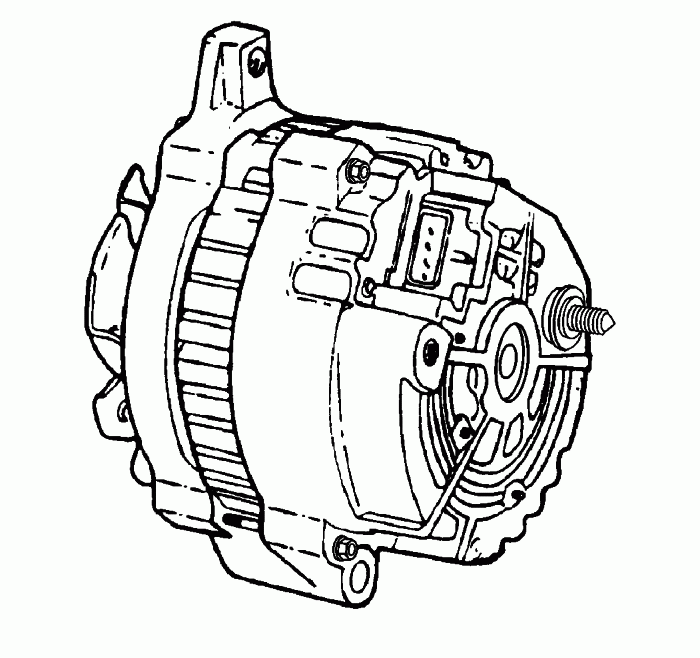


CS-Series generators feature a high ampere output per pound of weight. The CS stands for charging systems. The 130 or 144 is the measurement, in millimeters, of the outside diameter of the stator laminations.
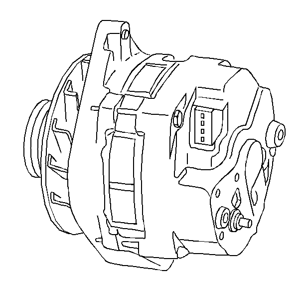


The CS-144 generator is a larger version of the CS-130. Unlike the CS-130, the CS-144 is serviceable.
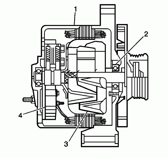


The CS-144 generator, with an internal regulator, does not have a diode trio. The delta stator (1), the rectifier bridge (4), and the rotor with slip rings and brushes (3), are electrically similar to other CS Series generators.

The generator uses a conventional fan and pulley. An internal fan cools the slip rings, the end frame, the rectifier bridge, and the regulator.

The charge indicator turns on when the ignition switch (gasoline engines) or the engine control switch (diesel engines) is closed and the engine is not running, and turns off when the engine is running. If the charge indicator is on with the engine running, this indicates a charging system condition. The indicator will glow at full brilliance, not half lit, if any of the following conditions occur:

Any charging condition
System voltage is too high or too low
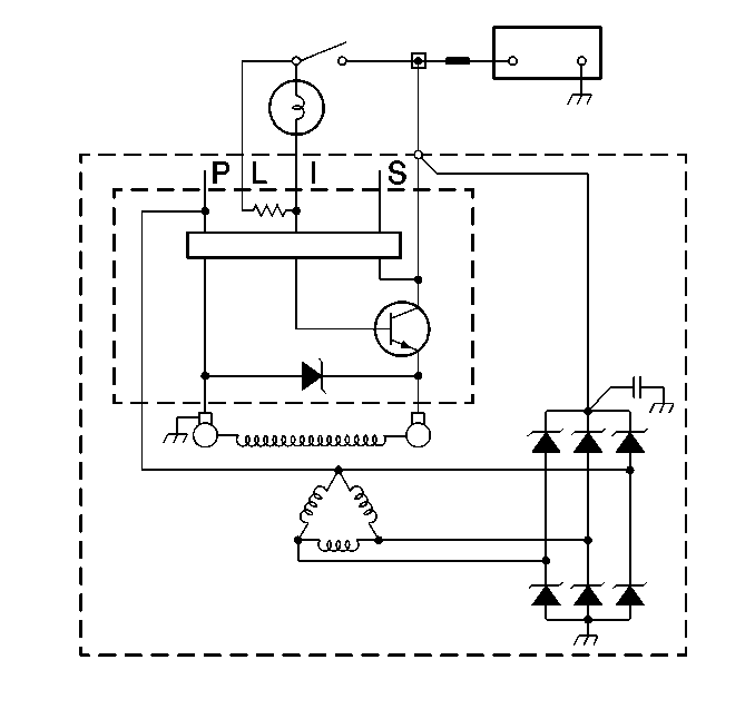


The regulator limits system voltage by controlling the rotor field current. When the field current is on, the regulator switches the rotor field on and off at a fixed rate of about 400 cycles per second. By varying the overall on/off time, correct average field current for proper system voltage control is maintained. At high speeds, the on time may be 10 percent and the off time may be 90 percent. At low speeds, and with high electrical loads, the on/off time may be 90 percent and 10 percent respectively.

The regulator has four terminals-- P, L, I, and S. On all P applications, P, L, I/F, and S is stamped on the regulator.

The L or the I terminal, or both, turns on the regulator and allows field current flow when the switch is closed. The L terminal must connect through an indicator lamp or a suitable resistor. The I terminal connects to B+ or through a resistor. These two terminals are often used in parallel and connected to two different vehicle circuits.

The P terminal connects internally to the stator and may be wired to a tachometer or other device. The S terminal may be used to "sense" voltage at another location on the vehicle for voltage control. If the S terminal is not used, the generator will use an integrated circuit in the regulator to "sense" voltage.

P model vehicles use a voltmeter in place of an indicator lamp. For schematics of the specific generator circuits, refer to Starting and Charging Schematics .

The CS-144 generator requires no periodic maintenance or adjustment. The CS-130 generator must be replaced. Do not disassemble the CS-130 generator.


--------------------------------------------------------------------------------
Charging Schematics
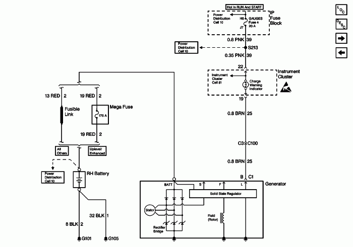
------------------
Cadillac Tech
ASE MASTER TECH since 1988

86 Northstar Fiero
85 RX7 former SCCA car
56 TR3 small mouth 6.0L
Formerly Washougal WA Resident
A.J. Whiteley

IP: Logged
wiccantoy
Member
Posts: 3372
From: northwales , pa / Williamstown nj
Registered: Mar 2002


Feedback score:    (9)
Leave feedback


Total ratings: 90
Rate this member

Report this Post04-02-2007 09:37 PM Click Here to See the Profile for wiccantoySend a Private Message to wiccantoyDirect Link to This Post
 
quote
Originally posted by AJxtcman:

Charging System Description


i like the discription but the local auto parts store has shown that the alt still works .
IP: Logged
AJxtcman
Member
Posts: 1098
From: Rock Hill SC
Registered: Nov 2006


Feedback score: N/A
Leave feedback

Rate this member

Report this Post04-02-2007 10:34 PM Click Here to See the Profile for AJxtcmanSend a Private Message to AJxtcmanDirect Link to This Post
Do you have power between the large Batt terminal and the case. I would use a Halogen head lamp bulb with two wires attached to it. If that is bright NOT DIM then it is OK. Then test the brown wire. A DVOM will not test this circuit properly. You can use a DVOM to test for 12 Volts with the key on between the brown wire and the case. You should read Battery voltage. If the battery only has 9.2 Volts it must be at least 9.0 volts. Next the wire will need to be tested with a test light it will be very dim or the GEN light will be on in the dash. If every thing is OK or you just want to skip to this test you can. Look on the back of the Alternator near the regulator for a opening shaped like a ...D.... about 3/8 to 1/2 inch you will find a Tab. The tab is part of the Regulator and is to full field the Alternator. You need to ground the Tab to the case while it is running. Use a small allen wrench, nail, pocket, screw driver. This will energize the alternator. I have got many new alternators that will not charge until this is done. Some times it take two times. The second time is after you shut off the car. I have used a DVOM and a logic test lamp on the Brown wire and have got false positives

------------------
Cadillac Tech
ASE MASTER TECH since 1988

86 Northstar Fiero
85 RX7 former SCCA car
56 TR3 small mouth 6.0L
Formerly Washougal WA Resident
A.J. Whiteley

[This message has been edited by AJxtcman (edited 04-02-2007).]

IP: Logged
wiccantoy
Member
Posts: 3372
From: northwales , pa / Williamstown nj
Registered: Mar 2002


Feedback score:    (9)
Leave feedback


Total ratings: 90
Rate this member

Report this Post04-02-2007 10:50 PM Click Here to See the Profile for wiccantoySend a Private Message to wiccantoyDirect Link to This Post
i have tryed 2 different alt's on the car. one of them i had tested and is good. the other im sure is good but cant be sure till i get it checked. i have the red thick wire that i can read power that the battery is holding , today i tryed the jumper trick on the red wire ( notta ) . ill have to try also useing your idea;s on the brown wire. i was kinda hopeing it was the inline fuse on the red. but since the jumper option didnt work , that option is out.
IP: Logged
AJxtcman
Member
Posts: 1098
From: Rock Hill SC
Registered: Nov 2006


Feedback score: N/A
Leave feedback

Rate this member

Report this Post04-03-2007 07:49 AM Click Here to See the Profile for AJxtcmanSend a Private Message to AJxtcmanDirect Link to This Post
I maybe wrong. I am not sure if this alternator has a opening to test for full field.
I have one at work and will check.
IP: Logged
wiccantoy
Member
Posts: 3372
From: northwales , pa / Williamstown nj
Registered: Mar 2002


Feedback score:    (9)
Leave feedback


Total ratings: 90
Rate this member

Report this Post04-03-2007 04:22 PM Click Here to See the Profile for wiccantoySend a Private Message to wiccantoyDirect Link to This Post
[i had i nice long post but i dont see it . oh well im off to try a few things posted

[This message has been edited by wiccantoy (edited 04-03-2007).]

IP: Logged
wiccantoy
Member
Posts: 3372
From: northwales , pa / Williamstown nj
Registered: Mar 2002


Feedback score:    (9)
Leave feedback


Total ratings: 90
Rate this member

Report this Post04-03-2007 04:42 PM Click Here to See the Profile for wiccantoySend a Private Message to wiccantoyDirect Link to This Post

wiccantoy

3372 posts
Member since Mar 2002
ok i pull the brown wire off and turn the ignition on and there is no power to that brown wire. is that what i was supposed to check for ?
IP: Logged
wiccantoy
Member
Posts: 3372
From: northwales , pa / Williamstown nj
Registered: Mar 2002


Feedback score:    (9)
Leave feedback


Total ratings: 90
Rate this member

Report this Post04-03-2007 05:03 PM Click Here to See the Profile for wiccantoySend a Private Message to wiccantoyDirect Link to This Post

wiccantoy

3372 posts
Member since Mar 2002
ok before i SCREAM i figured out my problem . ......... the alt and factory wireing REQUIRE that the rally guage is still hooked up. the brown wire from the alt goes to the rally guage. when i took it out i cut the loop . so now i need to figure out a way to use the circuit board from the rally guage so i can still use my auto meter guages..

from what i just tryed if the rally guage is in your car like mine. you need the volt light to work , i took the rally guages hooked them up and when i pulled the light for the alt light the alt stoped charging..... intresting. so im about to try putting a fuesable link between the 2 circuits and see if the alt will still charge without the guage and just the wires connected completeing the circuit. will report back

OK i completed the circuit with a 15 amp fuse connected and everything works . man i hate this car , no i dont , yes i do , no i dont... grrrrr. oh well i hope someone learns something from this post. thanks to all that helped...


only problem i can see with what i did when i completed the circuit it is like the light is on all the time . so the alt will always be trying to charge the battery. when it is running it is showing 16volts on the guage but 18 on the old guage is too high. so i guess ill be ok . anyone tend to disagree?

[This message has been edited by wiccantoy (edited 04-03-2007).]

IP: Logged
MaxCubes
Member
Posts: 693
From: El Paso, TX
Registered: Aug 2004


Feedback score: N/A
Leave feedback

Rate this member

Report this Post04-04-2007 09:33 PM Click Here to See the Profile for MaxCubesSend a Private Message to MaxCubesDirect Link to This Post
I did a search on the web and found a site that recommended and 10 ohm/ 10 watt (10% wire wound) resistor.

PN # 271-132 from Radio Shack

just splice it into the brown wire to a switched +12V source..... now my Alternator is charging beautifully
IP: Logged


All times are ET (US)

T H I S   I S   A N   A R C H I V E D   T O P I C
  

Contact Us | Back To Main Page

Advertizing on PFF | Fiero Parts Vendors
PFF Merchandise | Fiero Gallery | Ogre's Cave
Real-Time Chat | Fiero Related Auctions on eBay


Copyright (c) 1999, C. Pennock