This will start as VIN Y & 9 engine controls
I hope the info is in here Ryan.
2000 Cadillac DeVille - Engine - Engine Controls - 4.6L - Description and Operation
Catagories list
Powertrain Control Module (PCM)
Information Sensors/Switches Description
Powertrain Control Module Controlled Air Conditioning
Knock Sensor (KS) System
Electric Cooling Fan
Electronic Ignition (EI) System
Air Induction System
Fuel System Description
Fuel Supply Component Description
Fuel Metering Modes of Operation
Fuel Metering System Component Description
Evaporative Emission Control System
Secondary Air Injection System Description
Exhaust Gas Recirculation (EGR) System
Crankcase Ventilation System
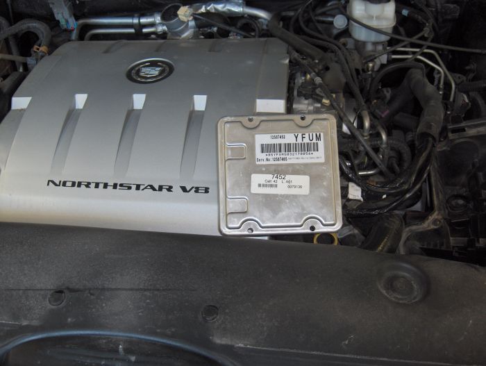
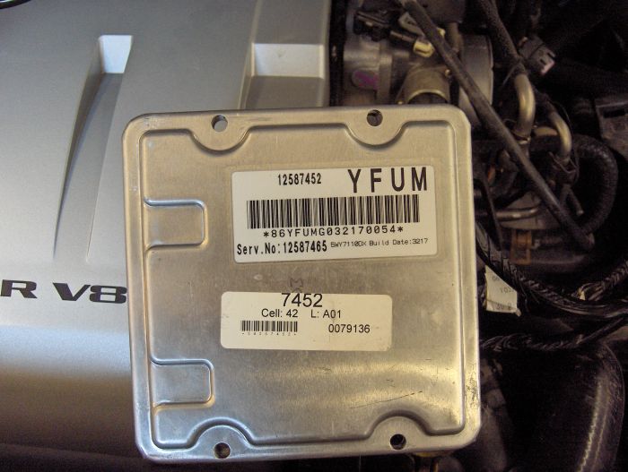
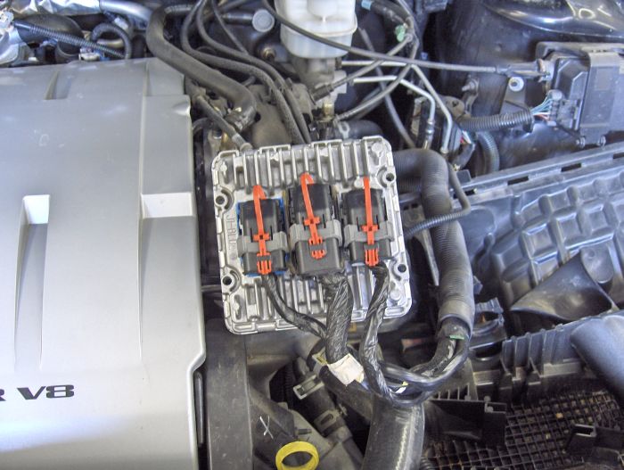
Powertrain Control Module (PCM)
Powertrain
The powertrain used in this vehicle consists of a twin cam V8 engine mated to a 4T80-E transaxle. The powertrain has electronic controls to reduce exhaust emissions while maintaining excellent driveability and fuel economy. The powertrain control module (PCM) manages the operation of the engine control system.
The powertrain control module is designed to maintain exhaust emission levels to Federal or California standards while providing excellent driveability and fuel efficiency. Review the components and wiring diagrams in order to determine which systems are controlled by the PCM. The PCM monitors numerous engine and vehicle functions. The following are some of the functions that the PCM controls:
� Engine fueling
� Ignition control (IC)
� Knock sensor (KS) system
� Evaporative Emission (EVAP) system
� Secondary Air Injection (AIR) system (if equipped)
� Exhaust Gas Recirculation (EGR) system
� Automatic transmission functions
� A/C clutch control
� Cooling fan control
Powertrain Control Module Function
The PCM constantly looks at the information from various sensors and other inputs, and controls systems that affect vehicle performance and emissions. The PCM also performs diagnostic tests on various parts of the system. The PCM can recognize operational problems and alert the driver via the malfunction indicator lamp (MIL). When the PCM detects a malfunction, it stores a diagnostic trouble code (DTC). The problem area is identified by the particular DTC that is set. The PCM supplies a buffered voltage (5V or 12V) to various sensors and switches. The input and output devices in the control module include analog to digital converters, signal buffers, counters, multiple function drivers, and output drivers. The multiple function drivers (i.e., EGR control, fuel pump relay) are electronic switches that supply ignition voltage to energize the circuit. The output drivers are electronic switches that, when energized, complete the ground path. Most PCM controlled components are operated via output drivers. The PCM monitors these driver circuits for proper operation. In most cases, if a problem is detected, a DTC corresponding to the controlled device will set.
Torque Management
Torque management is a function of the PCM that reduces engine power under certain conditions. Torque management is performed for three reasons:
� To prevent overstress of powertrain components
� To limit engine power when brakes are applied
� To prevent damage to the vehicle during certain abusive maneuvers
The PCM uses manifold vacuum, intake air temperature, spark retard, engine speed, engine coolant temperature, A/C clutch status, and EGR valve position to calculate engine output torque. It then looks at torque converter status, transaxle gear ratio, and brake switch inputs and determines if any torque reduction is required. If torque reduction is required, the PCM retards spark as appropriate to reduce engine torque output. In the case of abusive maneuvers, the PCM may also shut off fuel to certain cylinders to reduce engine power.
There are four instances when engine power reduction is likely to be experienced:
� During transaxle upshifts and downshifts
� Heavy acceleration from a standing start
� If brakes are applied with moderate to heavy throttle
� When the driver is performing stress-inducing (abusive) maneuvers such as shifting into gear at high throttle angles
In the first two instances, the driver is unlikely to even notice the torque management actions. In the other cases, engine power output will be moderate at full throttle.
When the PCM determines that engine power reduction is required, it calculates the amount of spark retard necessary to reduce power by the desired amount. This spark retard is then subtracted from the current spark advance. In the case of abusive maneuvers, the PCM will momentarily disable fuel injectors to obtain the necessary amount of torque reduction.
Traction Control
Traction control is a function of the PCM and electronic brake and traction control module (EBTCM) to reduce wheel slip during acceleration. When wheel slip is detected, the EBTCM applies the front brakes, and the PCM reduces engine power. Refer to Diagnostic System Check - ABS in Antilock Brake System for an explanation of the EBTCMs role in traction control. The PCM continuously sends the EBTCM a PWM signal to indicate the torque output of the powertrain. This signal, referred to as the Delivered Torque signal, is used by the EBTCM to determine the required action when it sees the front wheels slipping. The EBTCM may decide to apply the front brakes only, or apply the front brakes and signal the PCM to reduce the torque output of the powertrain. The EBTCM requests reduced torque using another PWM signal. This signal, referred to as the Desired Torque signal, is used by the PCM to determine the amount of torque reduction requested by the EBTCM. The PCM adjusts the ignition timing in response to the Desired Torque signal.
The Desired Torque signal varies within a range of 95 percent and 5 percent duty cycle. A duty cycle at 95 percent indicates no torque reduction. A duty cycle at 10 percent indicates full torque reduction. The Desired Torque signal to the PCM will normally be at a 90 percent duty cycle. The EBTCM will decrease the duty cycle of the signal by the amount of torque reduction desired. The PCM responds to the signal by adjusting the ignition timing. The PCM may shut off the fuel to one or more cylinders unless the following conditions are present:
� The coolant temperature is below -40�C (-40�F) or above 131�C (268�F).
� A low coolant level is present.
� The engine speed is below 600 RPM.
The PCM will re-enable the fuel injectors as the need for traction control ends.
Traction control will be disable when certain DTCs set. The PCM will request a TRACTION OFF light/message via Class 2 serial data when the DTCs set.
Class 2 Serial Data
The Class 2 serial data circuit allows the control modules to communicate with each other. The modules send a series of digital signals pulsed from high to low voltage (approximately 7 volts to 0 volts). These signals are sent in variable pulse widths of one or two bits. A string of these bits creates a message that is sent in a prioritized data packet. This allows more than one module to send messages at the same time without overloading the serial data line.
The speed, or BAUD rate, at which the control modules communicate depends on the message content. Large message content lowers the BAUD rate while small message content increases the BAUD rate. The average BAUD rate is approximately 10.4 kps (10,400 bits per second).
When the key is ON, each module sends a State of Health message to the other control modules using the Class 2 serial data line. This ensures that the modules are working properly. When the module stops communicating, a loss of the state of health message occurs. The control modules that expect to receive the message detect the loss, and will set a loss of the state of health diagnostic trouble code (DTC).
Data Link Connector (DLC)
The data link connector (DLC) provides a Class 2 data circuit that allows bi-directional communication between the scan tool, the PCM, and other system control modules. Usually located under the instrument panel, the DLC provides power and ground for the scan tool. Some common uses of the scan tool are listed below:
� Identifying stored diagnostic trouble codes (DTCs)
� Clearing DTCs
� Performing output control tests
� Reading serial data for diagnostic analysis
Service Engine Soon/Malfunction Indicator Lamp (MIL)
The service engine soon/malfunction indicator lamp (MIL) is located in the instrument panel cluster (IPC). The MIL is controlled by the PCM and is used to indicate that the PCM has detected a problem that affects vehicle emissions, may cause powertrain damage, or severely impacts driveability.
Trip
A trip is an interval of time during which the diagnostic test runs. A trip may consist of only a key cycle to power up the PCM, allow the diagnostic to run, then cycle the key off to power down the PCM. A trip may also involve a PCM power up, meeting specific conditions to run the diagnostic test, then powering down the PCM. The definition of a trip depends on the diagnostic. Some diagnostic tests run only once per trip (i.e., catalyst monitor) while other tests run continuously during each trip (i.e., misfire, fuel system monitors).
Warm-up Cycle
The PCM uses warm-up cycles to run some diagnostics, and to clear any diagnostic trouble codes (DTCs). A warm-up cycle occurs when the engine coolant temperature raises 22�C (40�F) from start-up. The engine coolant must also achieve a minimum temperature of 71�C (160�F). The PCM counts the number of warm-up cycles in order to clear the malfunction indicator lamp (MIL). The PCM will clear the DTCs when 40 consecutive warm-up cycles occur without a malfunction.
Diagnostic Trouble Code Display
DTCs can only be displayed with the use of a scan tool.
DTC Status
When the scan tool displays a DTC, the status of the DTC is also displayed. The following DTC statuses will be indicated only when they apply to the DTC that is set.
Fail This Ign. (Fail This Ignition): Indicates that this DTC failed during the present ignition cycle.
Last Test Fail: Indicates that this DTC failed the last time the test ran. The last test may have run during a previous ignition cycle if an A or B type DTC is displayed. For type C DTCs, the last failure must have occurred during the current ignition cycle to appear as Last Test Fail.
MIL Request: Indicates that this DTC is currently requesting the MIL. This selection will report type B DTCs only when they have requested the MIL. (failed twice).
Test Fail SCC (Test Failed Since Code Clear): Indicates that this DTC that has reported a failure since the last time DTCs were cleared.
History: Indicates that the DTC is stored in the PCMs History memory. Type B DTCs will not appear in History until they have requested the MIL (failed twice). History will be displayed for all type A DTCs and type B DTCs (which have requested the MIL) that have failed within the last 40 warm-up cycles. Type C DTCs that have failed within the last 40 warm-up cycles will also appear in History.
Not Run SCC (Not Run Since Code Clear): DTCs will be listed in this category if the diagnostic has not run since DTCs were last cleared. This status is not included with the DTC display since the DTC can not be set if the diagnostic has not run. This information is displayed when DTC Info is requested using the scan tool.
Clearing Diagnostic Trouble Codes
Use a scan tool to clear DTCs from the PCM memory. Disconnecting the vehicle battery to clear the PCM memory is not recommended. This may or may not clear the PCM memory and other vehicle system memories will be cleared. Do not disconnect the PCM connectors solely for clearing DTCs. This unnecessarily disturbs the connections and may introduce a new problem. Before clearing DTCs the scan tool has the capability to save any data stored with the DTCs and then display that data at a later time. Capture DTC info before beginning diagnosis (refer to Capturing DTC Info). Do not clear DTCs until you are instructed to do so within a diagnostic procedure.
Many PCM DTCs have complex test and failure conditions. Therefore, simply clearing DTCs and watching to see if the DTC sets again may not indicate whether a problem has been corrected. To verify a repair after it is complete, you must look up the test conditions and duplicate those conditions. If the DTC runs and passes, chances are good that the problem is fixed.
Freeze Frame Data
Government regulations require that engine operating conditions be captured whenever the MIL is illuminated. The data captured is called Freeze Frame data. The Freeze Frame data is very similar to a single record of operating conditions. Whenever the MIL is illuminated, the corresponding record of operating conditions is recorded as Freeze Frame data. A subsequent failure will not update the recorded information.
The Freeze Frame data parameters stored with a DTC failure include the following:
� Air fuel ratio
� Mass air flow sensor
� Fuel trim (both short term and long term for both cylinder banks)
� Engine speed
� Intake air temperature
� Engine coolant temperature
� Vehicle speed
� TP angle
� MAP/BARO
� Fuel System status
Freeze frame data can only be overwritten with data associated with a misfire or fuel trim malfunction. Data from these faults take precedence over data associated with any other fault. The Freeze Frame data will not be erased unless the associated history DTC is cleared.
Failure Records Data
When a diagnostic test fails, the PCM stores the information as Failure Records data. Unlike Freeze Frame data, Failure Records are stored for multiple DTCs or non-emission related DTCs (DTCs that do not illuminate the MIL). The Failure Records information is updated the first time the test fails during each ignition cycle.
Important: Always capture the Freeze Frame and Failure Records information with the scan tool BEFORE proceeding with diagnosis. Loss of this data may prevent accurate diagnosis of an intermittent condition.
Freeze Frame/Failure Records data may be retrieved through the scan tool. If more than one DTC is set review the odometer or engine run time data located in the Freeze Frame/Failure Records info to determine the most current failure. The stored information will look like normal PCM data.
Capturing DTC Info (Capture Info)
Selecting this option on the scan tool allows the technician to record the Freeze Frame and Failure Records that may be stored in the PCMs memory. Capture DTC info before beginning diagnosis. This is a step in the OBD System Check. At the end of the diagnostic tables, you are instructed to clear DTCs, verify that the repair was successful and then to review captured information. The captured information will contain any additional DTCs and related data that was stored originally (if multiple DTCs were stored).
Storing And Erasing Freeze Frame Data
Government regulations require that engine operating conditions be captured whenever the MIL is illuminated. The data captured is called freeze frame data. The freeze frame data is very similar to a single record of operating conditions. Whenever the MIL is illuminated, the corresponding record of operating conditions is recorded to the freeze frame buffer.
Each time a diagnostic test reports a failure, the current engine operating conditions are recorded in the freeze frame buffer. A subsequent failure will update the recorded operating conditions. The following operating conditions for the diagnostic test which failed typically include the following parameters:
� Air fuel ratio
� Air flow rate
� Fuel trim
� Engine speed
� Engine load
� Engine coolant temperature
� Vehicle speed
� TP angle
� MAP/BARO
� Injector base pulse width
� Loop status
Freeze frame data can only be overwritten with data associated with a misfire or fuel trim malfunction. Data from these faults take precedence over data associated with any other fault. The freeze frame data will not be erased unless the associated history DTC is cleared.
Storing and Erasing Failure Records Data
When a PCM DTC sets, the PCM does several things. Among them is to save useful data and input parameter information for service diagnosis. This information is referred to as Freeze Frame/Failure Records. You will see references to these in many PCM DTC diagnostic tables because this information can be useful in pinpointing a problem even if the problem is not present when the vehicle is in the service bay.
Freeze Frame/Failure Records data may be retrieved through the DTC menu on scan tool. If more than one DTC is set review the odometer or engine run time data located in the Freeze Frame/Failure Records info to determine the most current failure.
Keep in mind that once Freeze Frame or Failure Record is selected, the parameter and input data displayed will look just like the normal PCM data except the parameters will not vary since it is displaying stored data.
Capturing DTC Info (Capture Info)
Selecting this option on the scan tool allows the technician to record the Freeze Frame and Failure Records that may be stored in the PCMs memory. This can be useful if the PCM or battery must be disconnected and later review of the stored information may be desired.
PCM Snapshot Using A Scan Tool
The scan tool can be set up to take a snapshot of the parameters available via serial data. The snapshot function records live data over a period of time. The recorded data can be played back and analyzed. The scan tool can also graph parameters singly or in combinations of parameters for comparison. The snapshot can be triggered manually at the time a symptom is noticed, or set up in advance to trigger when a DTC sets. An abnormal value captured in the recorded data may point to a system or component that needs to be investigated further. The snapshot will remain in the scan tool memory even after the tool is disconnected from its power source. Refer to the scan tool user instructions for more information on the snapshot function.
Information Sensors/Switches Description
A/C Pressure Sensor
The PCM uses the A/C pressure sensor to monitor the high pressure side of the A/C system. The PCM supplies the sensor with a 5 volt reference and a ground. The sensor returns a signal voltage relative to the A/C refrigerant pressures. The PCM uses this information to turn ON the engine coolant fans when the A/C pressure is too high. If the sensor indicates that the A/C refrigerant pressure is too high or too low, the PCM will disengage the A/C compressor. If the PCM detects an A/C pressure sensor signal above or below the possible range of the sensor, DTC P0532 or DTC P0533 will set.
Crank Request
The crank request circuit is used to signal the PCM that the ignition switch is in the START position. With the ignition switch in the OFF position, the PCM should detect zero volts on the crank request circuit. With the ignition switch in the START position, the crank request circuit applies a fused ignition voltage to the PCM. The PCM uses the crank request signal, and other inputs to decide whether, or not to allow starter operation.
Engine Coolant Temperature (ECT) Sensor
The engine coolant temperature (ECT) sensor is a thermistor mounted in the engine coolant stream. The ECT sensor resistance varies from 100,000 ohms at -40�C (-40�F) to 70 ohms at 130�C (266�F). The PCM uses the ECT signal to calculate the coolant temperature. The PCM applies 5 volts to the ECT signal circuit through a pull-up resistor. When the engine coolant temperature is cold, the ECT sensor resistance is high. This causes the PCM to detect a high ECT signal voltage. When the engine coolant temperature increases, the sensor resistance lowers. The PCM should detect a low ECT signal voltage
The scan tool displays the engine coolant temperature in degrees. After engine startup, the coolant temperature should steadily rise to approximately 90�C (194�F). Then, when the thermostat opens, the temperature should stabilize. If the engine has not been run for several hours (overnight), the ECT sensor and IAT sensor scan tool displays should read close to each other. Engine coolant temperature affects most PCM controlled systems. A hard fault in the ECT sensor circuit should set DTC P0117 or P0118. An intermittent fault should set DTC P1114 or DTC P1115. To check ECT sensor resistance relative to temperature, refer to the Temperature vs Resistance table.
EGR Pintle Position Sensor
The EGR pintle position sensor is potentiometer used to indicate the amount of EGR valve opening. The PCM supplies the pintle position sensor with a 5 volt reference and a ground. The pintle position sensor provides a signal voltage to the PCM. By monitoring the voltage on the signal line, the PCM is able to determine if the EGR valve responds properly to commands from the PCM. As the EGR valve position changes, the pintle position signal voltage will change. With the EGR valve closed, the signal voltage is near 0 volts. However, the pintle position signal voltage increases as the EGR valve opens. When the PCM commands the EGR valve fully open, the pintle position signal voltage should be above 4 volts. If the PCM detects an excessively low pintle position signal voltage (circuit is open or shorted to ground), DTC P0405 will set.
When the ignition switch is in the RUN position, the PCM learns the EGR closed valve pintle position. When the PCM commands the EGR valve closed, the PCM compares the closed valve pintle position to the actual EGR position. If the actual EGR position indicates that the EGR valve is still open, DTC P1404 will set.
The PCM controls the EGR valve using an ignition voltage driver and ground located within the PCM. When the PCM commands the EGR valve open, the PCM compares the actual EGR position to the desired EGR position. If the actual EGR is less than the desired EGR by a calibrated amount, DTC P0404 will set. If an electrical malfunction occurs in the EGR valve control circuit, DTC P0403 will set.
Engine Oil Pressure Sensor
The engine oil pressure sensor is a rheostat mounted in the oil filter adapter. The PCM supplies the sensor with a 5 volt reference and a ground. The sensor varies the 5 volt input voltage relative to the oil pressure at various engine speeds. The PCM uses the signal voltage to calculate the amount of fuel in the tank.
The PCM sends the oil pressure information via Class 2 to the instrument panel cluster (IPC). The IPC uses the information to control the oil pressure indicator.
Fuel Tank Pressure Sensor
The PCM monitors the fuel tank pressure sensor to detect vacuum decay and excess vacuum during the EVAP system tests. The fuel tank pressure sensor measures the difference between the air pressure (or vacuum) in the tank and the outside air pressure. The PCM supplies a 5 volt reference and a ground for the fuel tank pressure sensor. The fuel tank pressure sensor provides a signal to the PCM that ranges between 0.1 and 4.9 volts.
Fuel Level Sensor PCM
The fuel level sensor is a rheostat mounted on the fuel sender assembly. The PCM supplies the sensor with a 5 volt reference and a ground. The sensor varies the 5 volt input voltage based on the level of fuel in the tank. The PCM uses the signal voltage to calculate the amount of fuel in the tank.
The fuel level sensor is part of the fuel sender assembly. The PCM uses the fuel level input to make sure that the level of fuel in the tank is sufficient to run the EVAP tests. The PCM also sends the fuel level information via Class 2 to the instrument panel cluster (IPC). The IPC uses the information to control the fuel level gauge.
The PCM performs the key ON and RUN tests to determine the status of the L-terminal circuit. During the key ON test, if the PCM detects a high signal voltage, DTC P0621 will set. DTC P0621 will also set if, during the RUN test, the PCM detects a low signal voltage. The PCM also sends a Class 2 serial data message to illuminate the charging telltale.
Generator L Terminal
The L-terminal circuit connects the generator to the PCM. The PCM applies ignition voltage to the L-terminal signal circuit through a resistor. The PCM should detect a low signal voltage input when the key is in the RUN position with the engine OFF, or when the charging system malfunctions. During engine operation, the PCM should detect a high signal voltage.
Generator F Terminal
The F-terminal circuit connects the generator to the PCM. The PCM uses this circuit to monitor the pulse width modulation (PWM) of the field circuit. When the key is in the RUN position and the engine is OFF, the PCM should detect a duty cycle near 0 percent. However, when the engine is running, the duty cycle should be between 5 percent and 100 percent.
The PCM monitors the PWM signal using a key ON test and a RUN test. During each test, if the PCM detects an out of range PWM signal, DTC P0622 will set. When the DTC sets, the PCM will send a Class 2 serial data message to illuminate the appropriate telltales.
Heated Oxygen Sensors (HO2S)
The heated oxygen sensors allow the PCM to maintain an air/fuel ratio that provides the best performance, fuel economy, and emission control. There are three heated oxygen sensors mounted in the exhaust gas stream. HO2S bank 1 sensor 1 and bank 2 sensor 1 are mounted in the right and left exhaust manifolds. HO2S bank 1 sensor 2 is mounted in the exhaust pipe after the converter. These sensors produce a voltage due to the difference in oxygen content between the air and the exhaust gas stream.
The PCM uses the fuel control heated oxygen sensors (HO2S bank 1 sensor 1 and bank 2 sensor 1) to decide what fuel mixture command to give the fuel injectors. The PCM supplies a 450 millivolt reference voltage to the sensors. The sensors vary the reference voltage in response to the oxygen content in the exhaust gas stream. When the oxygen content is low (a rich condition), the PCM will detect a signal voltage near 900 millivolts. When the oxygen content is high (a lean condition), the PCM will detect a signal voltage near 100 millivolts. The PCM adjusts the injector pulse width to correct for a rich or a lean condition. The PCM uses HO2S bank 1 sensor 2 to determine how well the three-way catalyst is controlling emissions.
The PCM compares the signals from HO2S bank 1 sensor 1 and bank 2 sensor 1 to the signal from HO2S bank 1 sensor 2. If the catalyst is operating efficiently, the PCM should detect a HO2S bank 1 sensor 2 signal less active than the signals from HO2S bank 1 sensor 1 and bank 2 sensor 1.
Intake Air Temperature (IAT) Sensor
The intake air temperature (IAT) sensor is a thermistor integrated with the mass air flow (MAF) sensor. The IAT sensor resistance varies from 100,000 ohms at 40�C (40�F) to 70 ohms at 130�C (266�F). The PCM uses the IAT signal to calculate the intake air temperature. The PCM applies 5 volts to the IAT signal circuit through a pull-up resistor. When the intake temperature is cold, the IAT sensor resistance is high. This causes the PCM to detect a high IAT signal voltage. As the underhood temperatures increase, the IAT sensor resistance lowers. The PCM should detect a low IAT signal voltage.
The scan tool displays the intake air temperature in degrees. The IAT sensor display should read close to ambient air temperature when the engine is cold. As the underhood temperature increases, the IAT sensor display should also increase. If the engine has not been run for several hours (overnight), the IAT sensor and ECT sensor scan tool displays should read close to each other. A hard fault in the IAT sensor circuit should set DTC P0112 or P0113. An intermittent fault should set DTC P1111 or DTC P1112. To check IAT sensor resistance relative to temperature, refer to the Temperature vs Resistance table.
Manifold Absolute Pressure (MAP) Sensor
The manifold absolute pressure (MAP) sensor responds to changes in intake manifold pressure. The PCM supplies a 5 volt reference and a ground for the MAP sensor. The MAP sensor provides a signal to the PCM relative to the pressure changes in the manifold. The MAP sensor signal voltage to the PCM varies from below 2 volts at idle (low manifold absolute pressure - high vacuum) to above 4 volts with the key ON, engine not running or at wide-open throttle (high manifold absolute pressure - low vacuum).
If the PCM detects a voltage that is lower than the possible range of the MAP sensor, DTC P0107 will set. A signal voltage higher that the possible range of the MAP sensor will set DTC P0108. An intermittent low or high voltage will set DTC P1107 or P1106 respectively.
Mass Air Flow (MAF) Sensor
The mass air flow (MAF) sensor measures the amount of air flow into the engine in a given time. The MAF sensor produces a signal as air passes through the sensor and into the engine. The amount of air flow determines the frequency of the signal. If the air flow through the sensor increases, the frequency of the signal will increase. If the air flow through the sensor decreases, the frequency of the signal will decrease. Normally, the frequency will vary from approximately 2000 hertz at idle to about 10,000 hertz at maximum engine load. The PCM uses the MAF sensor information to provide the correct fuel delivery for all engine operating conditions.
The scan tool displays the MAF value in grams per second (g/s). At idle, the scan tool should display a MAF value of 4 g/s - 7 g/s on a fully warmed engine. Values should change rather quickly on acceleration. However, the values should remain fairly stable at any given RPM.
If the PCM detects a signal frequency lower than the possible range of a normally operating MAF sensor, DTC P0102 will set. If the PCM detects a signal frequency higher than the possible range of a normally operating MAF sensor, DTC P0103 will set. If the actual MAF sensor frequency does not match a PCM calculated MAF value, DTC P0101 will set.
Throttle Position (TP) Sensor
The throttle position (TP) sensor is a potentiometer used to indicate the amount of throttle opening. The PCM supplies the TP sensor with a 5 volt reference and a ground. The TP sensor provides a signal voltage to the PCM relative to throttle blade angle. By monitoring the voltage on the signal line, the PCM calculates throttle position. As the throttle valve changes (accelerator pedal moves), the TP sensor output voltage will change. With the throttle closed, the signal voltage is low (below 1 volt). However, the TP sensor voltage increases as the throttle valve opens. At Wide Open Throttle (WOT), the TP sensor voltage should be above 4 volts.
The TP signal is one of the most important sensor inputs used by the PCM for controlling fuel and most of the PCM-controlled outputs. A malfunction in the TP sensor or related wiring should set DTC P0122 or DTC P0123. An intermittent condition will set DTC P1121 or DTC P1122. If the actual TP sensor signal does not match a PCM calculated TP value, DTC P0121 will set.
Knock Sensor
The PCM uses a knock sensor (KS) to detect abnormal vibration in the engine (detonation/spark knocking). Mounted in the engine block, under the intake manifold, the knock sensor produces an AC signal at all engine speeds and loads. The PCM then adjusts the spark timing based on the amplitude and frequency of the KS signal.
A knock sensor module is no longer used to diagnose the knock sensor system. The circuitry is integrated into the PCM. The PCM uses the knock sensor signal to calculate an average voltage. Then, the PCM assigns a voltage range above and below the average voltage value. The PCM checks the knock sensor and related wiring by comparing the actual knock signal to the assigned voltage range. A normal knock sensor signal should vary outside the assigned voltage range.
If the PCM malfunctions in a manner that will not allow proper diagnosis of the knock sensor and related wiring, DTC P0325 will set. If the PCM detects a knock signal input within the assigned voltage range, DTC P0327 will set. Refer to Knock Sensor (KS) System for a complete description of the knock sensor system.
Torque Converter Clutch (TCC)/Extended Travel Brake Switches
The PCM uses the input from the torque converter clutch (TCC) and extended travel brake switches to determine the state of the brake pedal (applied or released). The PCM uses the TCC switch input to mainly control the transaxle torque converter clutch (TCC). The PCM sends the extended travel brake switch input, via Class 2, to the EBTCM for braking and traction control management. The switches receive power through a fused ignition feed (hot in RUN and START). With the ignition in the RUN or CRANK position, and the brakes not applied, the PCM should detect ignition voltage. With the brakes applied, the PCM should detect zero volts.
The cruise control module also uses the input from the TCC brake switch. The cruise control system will disengage cruise operation when the TCC brake switch input indicates that the brakes are applied.
Powertrain Control Module Controlled Air Conditioning
I skipped this section
Knock Sensor (KS) System
Purpose
Varying octane levels in todays gasoline may cause detonation in some engines. Detonation is caused by an uncontrolled explosion (burn) in the combustion chamber. This uncontrolled explosion could produce a flame front opposite that of the normal flame front produced by the spark plug. The rattling sound normally associated with detonation is the result of two or more opposing pressures (flame fronts) colliding within the combustion chamber. Though light detonation is sometimes considered normal, heavy detonation could result in engine damage. To control spark knock, a knock sensor (KS) system is used. This system is designed to retard spark timing when spark knock is detected in the engine. The KS system allows the engine to use maximum spark advance for optimal driveability and fuel economy.
Operation
The PCM uses a knock sensor (KS) to detect abnormal vibration in the engine (detonation/spark knocking). Mounted in the engine block, under the intake manifold, the knock sensor produces an AC signal at all engine speeds and loads. The PCM then adjusts the spark timing based on the amplitude and frequency of the KS signal.
A knock sensor module is no longer used to diagnose the knock sensor system. The circuitry is integrated into the PCM. The PCM uses the knock sensor signal to calculate an average voltage. Then, the PCM assigns a voltage range above and below the average voltage value. The PCM checks the knock sensor and related wiring by comparing the actual knock signal to the assigned voltage range. A normal knock sensor signal should vary outside the assigned voltage range (as shown in the normal knock sensor figure). If PCM detects a signal voltage within the assigned voltage range, DTC P0327 will set (as shown in the abnormal knock sensor figure).
(1) Upper Fail Region
(2) Knock Sensor Calculated Average
(3) Knock Sensor Signal (Normal)
(4) Lower Fail Region
(1) Upper Fail Region
(2) Knock Sensor Calculated Average
(3) Knock Sensor Signal (Failed)
(4) Lower Fail Region
Diagnosis
If the PCM malfunctions in a manner which will not allow proper diagnosis of the KS circuits, DTC P0325 will set.
DTC P0327 is designed to diagnose the knock sensors, and related wiring. Problems encountered with the KS system should set a DTC. However, refer to Detonation/Spark Knock in Symptoms if no DTC sets, and the customers complaint of detonation points to the KS system.
Electric Cooling Fan
The electric cooling fans cool the engine coolant flowing through the radiator. The electric cooling fans also cool the refrigerant (R134a) flowing through the A/C condenser.
The engine cooling fan system consists of two electric cooling fans and three fan relays that are controlled by the PCM. The cooling fans receive power from two separate 30A maxifuses located in the Underhood Fuse Block Assembly. The relays are wired in a series/parallel arrangement that allows the PCM to operate both fans together at low or high speed.
During low speed operation, the PCM supplies the ground path for the low speed fans relay through the low speed fans control circuit. This energizes the relay coil, closes the relay contacts, and supplies current to the engine cooling fans. The ground path for the right engine cooling fan is through the series/parallel cooling fan relay and the left engine cooling fan. The result is a series circuit with both fans running at low speed.
To command high speed cooling fan operation the PCM first supplies the ground path for the low speed cooling fans relay through the low speed fans control circuit. After a 3 second delay, the PCM supplies the ground path for the high speed cooling fan relay and the series/parallel cooling fan relay through the high speed fans control circuit. During high speed operation, both engine cooling fans are supplied current through their respective maxifuse and each fan has its own ground path.
PCM will command fan operation under the following conditions:
Low Speed Fan Operation
The engine coolant temperature exceeds approximately 106�C (229�F).
The transmission fluid temperature exceeds 150�C (302�F).
The A/C operation is requested.
After the vehicle is shut OFF if the coolant temperature at key-off is more than 151�C (304�F) and system voltage was more than 12 volts. The fans will stay ON for approximately 3 minutes.
The fans will switch from low to OFF when the coolant drops below 102�C (216�F).
High Speed Fan Operation
The engine coolant temperature reaches 112�C (234�F).
The transmission temperature is more than 151�C (304�F).
When certain DTCs set
The fans will switch from high to low, except when DTCs set, when the coolant drops below 106�C (229�F).
Electronic Ignition (EI) System
Ignition System Overview
The electronic ignition system controls fuel combustion by providing a spark to ignite the compressed air/fuel mixture at the correct time. To provide optimum engine performance, fuel economy, and control of exhaust emissions, the PCM controls the ignition system. The electronic ignition system has the following advantages over a mechanical distributor system:
No moving parts
Less maintenance
Remote mounting capability
No mechanical load on the engine
More coil cool down time between firing events
Elimination of mechanical timing adjustments
Increased available ignition coil saturation time
Operation
The electronic ignition system does not use the conventional distributor and coil. The ignition system consists of the following components/circuits:
Eight ignition coils
Eight ignition control (IC) circuits
Two ignition control modules (one per cylinder bank)
Camshaft position (CMP) sensor
Crankshaft position (CKP) sensor A
Crankshaft position (CKP) sensor B
Related connecting wires
Powertrain control module (PCM)
Crankshaft Position Sensors
The PCM uses dual crankshaft position (CKP A and CKP B) sensors to determine crankshaft position. The CKP sensors are mounted in the engine block approximately 21.5 degrees apart from each other. Three wires connect each CKP sensor to the PCM. The PCM supplies an ignition voltage and a ground for each CKP sensor. During engine rotation, a slotted ring, machined into the crankshaft, causes the sensors to return a series of ON and OFF pulses to the PCM. The PCM uses these pulses to decode the position of the engine crankshaft.
The PCM uses two basic methods of decoding the engine position: Angle Based and Time Based (using either CKP A or CKP B sensor input). During normal operation, the PCM uses the angle based method. In order to operate in this mode, the PCM must receive signal pulses from both CKP sensors. The PCM uses the signal pulses to determine an initial crankshaft position, and to generate MEDRES (24X reference) and LORES (4X reference) signals. Once the initial crank position is determined, the PCM continuously monitors both sensors for valid signal inputs. As long as both signal inputs remain, the PCM will continue to use the angle based mode.
When either CKP signal is lost, the PCM will compare the MEDRES signal to the camshaft position (CMP) sensor signal. If the PCM detects a valid CMP signal, and the MEDRES to CMP signal correlation is correct, the PCM determines that CKP sensor A is at fault. However, if the MEDRES to CMP correlation is incorrect, the PCM determines that CKP sensor B is at fault.
If the PCM detects a loss of signal for CKP sensor A, DTC P0335 will set. The PCM will switch from angle based mode to Time Based mode B using CKP sensor B signal input. If the PCM detects a loss of signal for CKP sensor B, DTC P0385 will set. The PCM will switch from angle based mode to Time Based mode A using CKP sensor B signal input. A noisy signal input from either CKP sensor will cause the ignition system to re-sync. If the number of ignition system re-sync is more than a calibrated amount, DTC P1372 will set.
Camshaft Position Sensor
The camshaft position (CMP) sensor is mounted in the front of the right cylinder head assembly. The CMP sensor signal, when combined with the CKP sensor signal, enables the PCM to determine exactly which cylinder is on a firing stroke. The PCM can then properly synchronize the ignition system, fuel injectors and knock control. The PCM supplies an ignition voltage and a ground for the CMP sensor. If a problem is detected with the CMP circuit, DTC P0340 or P0341 will set.
Ignition Coils/Modules
The electronic ignition system uses an individual ignition coil for each cylinder. There are two separate ignition module assemblies located in the camshaft cover of each cylinder bank. Each ignition module assembly contains an ignition control module and four ignition coils. Each ignition coil connects directly to a spark plug using a boot. This arrangement eliminates the need for secondary ignition wires. The ignition module assemblies receive power from a fused ignition feed. Both ignition module assemblies connect to chassis ground. A Reference Low and four ignition control (IC) circuits connect each ignition module assembly to the PCM. The PCM uses the individual IC circuits to control coil sequencing and spark timing for each ignition coil. The IC circuits transmit timing pulses from the PCM to the ignition control module to trigger the ignition coil and fire the spark plug. The PCM controls ignition system sequencing and timing events.
This ignition system produces very high energy to fire the spark plug. There is no energy loss because of ignition wire resistance, or the resistance of the waste spark system. Also, since the firing is sequential, each coil has seven ignition events to saturate as opposed to the three in a waste spark arrangement.
Noteworthy Ignition Information
There are important considerations to point out when servicing the ignition system. The following noteworthy information will list some of these, to help the technician in servicing the ignition system.
The ignition coils secondary voltage output capabilities are very high - more than 40,000 volts. Avoid body contact with ignition high voltage secondary components when the engine is running, or personal injury may result!
The crankshaft position sensor clearance is very important! The sensor must not contact the reluctor wheel at any time, or sensor damage will result. If the reluctor wheel contacts the sensors, destruction of the sensors will occur.
Ignition timing is not adjustable. There are no timing marks on the crankshaft pulley.
If a boot remains attached to a coil or spark plug, twist the boot prior to removal using the correct tool. Do not use pliers, screwdrivers, or any unauthorized tools to remove the boot.
Check the boot for a missing or damaged internal spring.
Do not re-install any component that has visible signs of damage.
Install the boots onto the coils (until bottomed out). Then install the assembly onto the spark plugs. If this is not possible due to space limitations, just-start the boots onto the spark plugs and then install the coil assembly as straight down onto the plugs as possible.
Ensure the boots are installed right side up.
Repair a torn perimeter seal with RTV sealant.
Adhere to the torque specifications when installing the cassette to the cam cover and the module to the cassette.
Powertrain Control Module (PCM)
The PCM is responsible for maintaining proper spark and fuel injection timing for all driving conditions. To provide optimum driveability and emissions, the PCM monitors input signals from the following components in calculating ignition control (IC) spark timing:
Engine coolant temperature (ECT) sensor
Intake air temperature (IAT) sensor
Mass air flow (MAF) sensor
Trans range inputs from transaxle range switch
Throttle position (TP) sensor
Vehicle speed sensor (VSS)
Reference Low Circuits
The reference low circuits provide a common ground between the PCM, and the ignition control modules. These circuits reduce the electrical ground shifts that may occur between the PCM and the ignition control modules. A malfunction in the reference low circuits may cause a poor driveability condition.
Results of Incorrect Operation
An Ignition control circuit that is open, grounded, or short to voltage will set an ignition control circuit DTC. If a fault occurs in the IC output circuit when the engine is running, the engine will experience a misfire. DTCs P0351-P0358 indicate that a malfunction has been detected on an Ignition Control circuit. DTCs P1359 and P1360 will set when the PCM detects random malfunctions in ignition control circuit.
Air Induction System SKIPPED
Fuel System Description
System Operation
The function of the fuel and air control system is to manage fuel and air delivery to each cylinder to optimize the performance and driveability of the engine under all driving conditions. The fuel supply is stored in a high density polyethylene (HDPE) fuel tank located in front of the rear wheels. The fuel sender allows retrieval of fuel from the tank and also provides information on fuel level. A fuel pump contained in the modular fuel sender pumps fuel through nylon pipes and an in-line fuel filter to the fuel rail. The pump is designed to provide fuel at a pressure above the regulated pressure needed by the injectors. Fuel is then distributed through the fuel rail to eight injectors inside the intake manifold. Fuel pressure is controlled by a pressure regulator mounted on the fuel rail. The fuel system in this vehicle is recirculating, this means that excess fuel that is not injected into the cylinders is sent back to the fuel tank by a separate nylon pipe. This removes air and vapors from the fuel as well as keeping the fuel cool during hot weather operation. Each fuel injector is located directly above each cylinder's two intake valves. An accelerator pedal in the passenger compartment is linked to a throttle valve in the throttle body by a cable. The throttle body regulates air flow from the air cleaner into the intake manifold, which then distributes this air to each cylinder's two intake valves. This allows the driver to control the air flow into the engine, which then controls the power output of the engine.
Engine Fueling
Unleaded fuel must be used with all gasoline engines for proper emission control system operation. Using unleaded fuel will also minimize spark plug fouling and extend engine oil life. Leaded fuel can damage the emission control system, and its use can result in loss of emission warranty coverage.
All vehicles with gasoline engines are equipped with an evaporative emission control (EVAP) System that minimizes the escape of fuel vapors to the atmosphere. Information on this system is found in Driveability and Emissions (Powertrain and Emissions System).
The Northstar engine is fueled by eight individual injectors, one for each cylinder, that are controlled by the PCM. The PCM controls each injector by energizing the injector coil for a brief period generally once every other engine revolution. The length of this brief period, or pulse, is carefully calculated by the PCM to deliver the correct amount of fuel for proper driveability and emissions control. The length of time the injector is energized is called the pulse width and is measured in milliseconds (thousandths of a second).
While the engine is running, the PCM is constantly monitoring its inputs and recalculating the appropriate pulse width for each injector. The pulse width calculation is based on the injector flow rate (mass of fuel the energized injector will pass per unit of time), the desired air/fuel ratio, and actual air mass in each cylinder and it is adjusted for battery voltage, short term and long term fuel trim. The calculated pulse is timed to occur as each cylinders intake valves are closing to attain largest duration and most vaporization.
Fueling during crank is slightly different than during engine run. As the engine begins to turn, a prime pulse may be injected to speed starting. As soon as the PCM can determine where in the firing order the engine is, it begins pulsing injectors. The pulse width during crank is based on coolant temperature and barometric pressure.
The Northstar fueling system has several automatic adjustments to compensate for differences in fuel system hardware, driving conditions, fuel used, and vehicle aging. The basis for fuel control is the pulse width calculation described above. Included in this calculation are an adjustment for battery voltage, short term fuel trim, and long term fuel trim. The battery voltage adjustment is necessary since changes in voltage across the injector affect injector flow rate. Short term and long term fuel trims are fine and gross adjustments to pulse width designed to maximize driveability and emissions control. These fuel trims are based on feedback from oxygen sensors in the exhaust stream and are only used when the fuel control system is in closed loop.
Under certain stringent conditions, the fueling system will not energize injectors, individually or in groups, for a period of time. This is referred to as Fuel shut-off. Fuel shut-off is used to improve traction, save fuel, improve starting, and protect the vehicle under certain extreme or abusive conditions.
In case of a major internal problem, the PCM is equipped with a back-up fueling system that will run the engine until service can be performed.
Notice: Do not operate the engine in the back-up fuel for extended periods. Back-up fueling will negatively impact driveability and fuel economy, and may cause damage to the emissions system.
As part of the fueling system, the PCM records and sends data about fueling to the IPC from which the IPC calculates fuel economy, range, and fuel used displays. The PCM calculates the amount of fuel delivered to the engine through the injectors based on injector pulse width and flow rate. This data is accumulated and sent to the IPC periodically via the data link.
The PCM controls the fuel injectors based on information it receives from several information sensors. Each injector is fired individually in engine firing order, which is called Sequential Multiport Fuel Injection. This allows precise fuel metering to each cylinder and improves driveability under all driving conditions.
Fuel Quality
Due to increasing awareness towards vehicle emissions, evaporative and exhaust, and their impact on the environment, federal regulations are limiting certain characteristics of fuel. These limitations are causing driveability problems that are extremely difficult to diagnose. In order to make a diagnosis, a basic understanding of fuel and its effects on the vehicles fuel system must be gained.
Octane
Octane is a measure of a fuel's ability to resist spark knock. Spark knock occurs in the combustion chamber just after the spark plug fires, when the air/fuel mixture in the cylinder does not completely burn. The remaining mixture spontaneously combusts due to temperature and pressure. This secondary explosion causes a vibration that is heard as a knock (ping). Fuel with a high octane number has a greater resistance to spark knock. This vehicle requires 91 octane ([R+M]/2 method) in order to ensure proper performance of the fuel control system. Using fuel with an octane rating lower than 91 can create spark knock, which would cause the PCM to retard ignition timing to eliminate the knock. In a case such as this, poor engine performance and reduced fuel economy could result. Also, in severe knock cases, engine damage may occur.
Volatility
Volatility is a fuel's ability to change from a liquid state to a vapor state. Since liquid gasoline will not burn, it must vaporize before entering the combustion chamber. The rate at which gasoline vaporizes determines the amount of evaporative emissions released from the fuel system, and therefore has made volatility an environmental concern. The federal government has lowered the maximum allowable volatility, but certain driveability conditions have resulted.
Volatility can be determined through three different tests: the Vapor-Liquid Ratio, the Distillation Curve, and the Reid Vapor Pressure Test (RVP). The Vapor-Liquid Ratio test determines what temperatures must exist to create a vapor-liquid ratio of 20. The distillation curve is a graph showing the relationship between temperature and the percentage of fuel evaporated. The fuel components that boil at relatively low temperatures (below about 90�F) are known as light ends, and those that boil at about 300�F are known as heavy ends. The light ends are important for cold starting and cold weather driveability. Heavy ends provide engine power and are important for hot weather driveability. It is the proper mixture of these components that provide proper operation across a wide range of temperatures. However, the distillation curve of a gasoline usually requires laboratory testing. The Reid Vapor Pressure (RVP) test measures the pressure (psi) vaporized fuel exerts within a sealed container when heated to 100�F. Volatility increases proportional to RVP. While RVP can easily be measured in the field, it may be misleading because it is possible for two fuels with the same RVP to have different distillation curves, and therefore, different driveability characteristics.
As stated, improper volatility can create several driveability problems. Low volatility can cause poor cold starts, slow warm ups, and poor overall cold weather performance. It may also cause deposits in the crankcase, combustion chambers, and spark plugs. Volatility that is too high could cause high evaporative emissions and purge canister overload, vapor lock, and hot weather driveability conditions. Since volatility is dependent on temperature, different fuels are used during certain seasons of the year, thus creating problems during sudden temperature changes.
Fuel System Deposits
Fuel system deposits can cause various driveability problems. Deposits usually occur during hot soaks after key Off. Poor fuel quality or driving patterns such as short trips followed by long cool down periods can cause injector deposits. This occurs when the fuel remaining in the injector tip evaporates and leaves deposits. Leaking injectors can increase injector deposits. Deposits on fuel injectors affect their spray pattern, which in turn could cause reduced power, unstable idle, hard starts, and poor fuel economy.
Intake valve deposits can also be related to fuel quality. While most fuels contain deposit inhibitors, some do not, and the effectiveness of deposit inhibitors varies by manufacturer. If intake valve deposits occur, fuel may be suspected. These deposits can cause symptoms such as excessive exhaust emissions, power loss, and poor fuel economy.
Sulfur Content
The sulfur content in fuel is also regulated to a certain standard. Premium grades of fuel generally have a lower sulfur content than the less expensive blends. A high sulfur content can promote the formation of acidic compounds that could deteriorate engine oil and increase engine wear. It could also produce excessive exhaust emissions or a rotten egg smell from the exhaust system.
Oxygenated Fuels and Alcohol Content
Notice: Do not use fuels containing methanol in order to prevent damage and corrosion to the fuel system.
Methanol can corrode metal parts in the fuel system, and can also damage plastic and rubber parts.
Oxygenated fuels contain oxygen in their chemical structure. The advantages that oxygenated fuels offer are improved octane quality, better combustion, and reduced carbon monoxide emissions. To provide cleaner air, all gasolines in the United States are now required to contain additives that will help prevent deposits from forming in the engine and fuel system. Therefore, nothing should be added to the fuel. The most commonly used oxygenated fuels are ethanol (grain alcohol) and MTBE (Methyl Tertiary Butyl Ether).
Fuel Supply Component Description
On-Board Refueling Vapor Recovery System (ORVR)
The on-board refueling vapor recovery system (ORVR) is an on-board vehicle system to recover fuel vapors during the vehicle re-fueling operation. The flow of liquid fuel down to the fuel tank filler neck provides a liquid seal. The purpose of the ORVR is to prevent re-fueling vapor from exiting the fuel tank filler neck.
The ORVR components include:
� Fuel tank
� Fuel tank filler pipe
� EVAP canister
� Vapor lines
� Check valve
� Modular fuel sender--fuel tank pressure sensor located on modular fuel sender cover
� Fuel limiter vent valve (FLVV)
� Pressure vacuum relief valve
� Vapor recirculation line
� Variable orifice valve
The on-board refueling vapor recovery system (ORVR) is an on-board vehicle system designed to recover fuel vapors during the vehicle refueling operation. The flow of liquid fuel down the filler neck provides a liquid seal which prevents vapor from leaving the fuel system by transporting vapor to the EVAP canister for use by the engine. Listed below are the ORVR system components with a brief description of their operation:
� Fuel tank--Contains the modular fuel sender, fuel limiter vent valve, and three rollover valves.
� Fuel filler pipe--The pipe which carries fuel from the fuel nozzle to the fuel tank.
� EVAP canister--The EVAP canister receives refueling vapor from the fuel system, stores the vapor and releases the vapor to the engine upon demand.
� Vapor lines--Transports fuel vapor from the tank assembly to the EVAP canister.
� Check valve--The check valve limits fuel spit-back from the fuel tank during the refueling operation by allowing fuel flow only into the fuel tank. This check valve is located at the bottom of the fuel filler pipe.
� Modular fuel sender assembly--This assembly pumps fuel to the engine from the fuel tank.
� Fill limiter vent valve (FLVV)--This valve acts as a shut-off valve located in the fuel tank and has the following functions:
- Controls the fuel tank fill level by closing the primary vent from the fuel tank.
- Prevents fuel from exiting the fuel tank via the vapor line to the canister.
- Provides fuel-spillage protection in the event of a vehicle rollover by closing the vapor path from the tank to the EVAP canister.
� Pressure/vacuum relief valve--The pressure/vacuum relief valve provides venting of excessive fuel tank pressure and vacuum. The valve is located in the fuel filler neck on a plastic fuel tank.
� Vapor recirculation line--The vapor recirculation line is used to transport vapor from the fuel tank to the top of the fill pipe during the refueling to reduce vapor loading to the enhanced EVAP canister.
� Variable orifice valve--The variable orifice valve regulates the amount of vapor allowed to enter the vapor recirculation line.
Fuel Tank
The fuel storage tank is made of high density polyethylene and is located in front of the rear wheels. It is held in place by two metal straps attached to the under body of the vehicle. The tank shape includes a sump to maintain a constant supply of fuel around the fuel pump strainer during low fuel conditions or aggressive maneuvers. The tank also contains a fuel vapor vent valve with roll-over protection. The vent valve also features a two phase vent calibration which increases fuel vapor flow to the canister when operating temperatures increase the tank pressure beyond an established threshold.
Fuel Tank Filler Pipe
(1) Fuel Tank Filler Pipe
(2) Fuel Tank Filler Pipe Clamp
(3) Fuel Tank
To help prevent refueling with leaded fuel, the fuel filler pipe has a built-in restrictor and deflector. The opening in the restrictor will accept only the smaller unleaded gasoline fuel nozzle which must be fully inserted to bypass the deflector. The filler pipe is attached to the tank by a section of hose and a clamp. The tank is vented during filling by an internal vent tube inside the filler pipe.
Fuel Filler Cap
(1) Fuel Tank Filler Cap
(2) Fuel Tank Filler Pipe
(3) Fuel Filler Door
The Enhanced EVAP fuel tank pipe cap has a tether connected to the fuel filler pipe door.
Notice: If a fuel tank filler pipe cap requires replacement, use only a fuel tank filler pipe cap with the same features. Failure to use the correct fuel tank filler pipe cap can result in a malfunction of the fuel system. A loose or incorrect fuel tank filler pipe cap can set a DTC.
Fuel Tank Vapor Pressure Sensor
The fuel tank pressure sensor is used to detect small leaks in the evaporative emission system. The fuel tank pressure sensor is a three wire strain gauge sensor much like that of the common GM MAP sensor. However, this sensor has very different electrical characteristics due to its pressure differential design. The sensor measures the difference between the air pressure (or vacuum) in the fuel tank and the outside air pressure. The sensor mounts at the top of the fuel tank. A three wire electrical harness connects it to the powertrain control module (PCM). The PCM supplies a five volt reference voltage and ground to the sensor. The sensor will return a voltage between 0.1 and 4.9 volts. When the air pressure in the fuel tank is equal to the outside air pressure, such as when the fuel fill cap is removed, the output voltage of the sensor will be 1.3 to 1.7 volts.
Enhanced Evaporative Emission (EVAP) Service Port
The enhanced EVAP service port is located in the evaporative purge hose located between the purge solenoid and the EVAP canister. The service port is identified by a green colored cap. The port contains a schrader valve and fittings to allow the connection of the J 41413 , evaporative pressure/purge diagnostic system.
Modular Fuel Sender - Fuel Level Sensor
The modular fuel sender assembly mounts to the threaded opening of the plastic fuel tank with a multi-lipped seal and lock ring. The spring loaded reservoir, containing the exterior inlet strainer, electric fuel pump, and pump strainer, maintains contact with the tank bottom. This design provides:
� Optimum fuel level in the integral fuel reservoir during all fuel tank levels and driving conditions.
� Improved tank fuel level measuring accuracy.
� Improved coarse straining and added pump inlet filtering.
� More extensive internal fuel pump isolation for noiseless operation.
The modular fuel sender assembly consists of the following major components:
� A fuel sender cover assembly
� A fuel sender
� Fuel pipes--above cover
� A fuel sender support assembly
� A fuel pump
� A fuel pump strainer
� A fuel pump reservoir
� A fuel sender strainer
� A fuel level sensor assembly
Modular Fuel Sender - Fuel Flow
(1) Fuel Feed
(2) Fuel Return
(3) Convoluted Fuel Tube (Flex Pipe)
(4) Secondary Umbrella Valve
(5) External Fuel Pump Strainer
(6) Fuel Flow from External Strainer
(7) Fuel Pump Strainer
(8) Fuel Pump
The modular fuel sender assembly maintains optimum fuel level in the reservoir (bucket). Fuel entering the reservoir (bucket) is drawn in by:
� The first stage of the fuel pump through the external strainer. And/Or
� The secondary umbrella valve, Or
� The return fuel pipe, whenever the level of fuel is below the top of the reservoir.
The fuel pump used in this system is part of the fuel sender assembly. The fuel pump lower connector assembly prevents the transmission of vibration and noise generated by the pump to the fuel tank.
Fuel enters the lower inlet port (secondary umbrella valve located inside of lower inlet port) of the electric fuel pump after being filtered by the external fuel strainer, and the fuel pump strainer. The initial function of the pump is to fill the reservoir.
The second stage separates vapor from the fuel in the pump. This vapor separation maximizes hot fuel handling and permits the vapor to return to the fuel tank at lower pressure and temperature. By creating positive fuel pressure, the pump then discharges the liquid fuel into the third stage of the pump. The pump outlet allows the fuel volume to flow through a check valve into the fuel pump flex pipe. The check valve seat is molded inside the connector body. The check valve body and retainer are assembled into the connector body. The check valve restricts fuel back flow.
After the fuel pump flex pipe, the fuel exits the assembly through the fuel feed output fitting on the molded cover. The cover also contains a fuel return provision which connects to one of three hollow support pipes.
Modular Fuel Sender Assembly
(1) Fuel Tank Pressure Sensor
(2) Fuel Pipes
(3) Fuel Pump
(4) External Fuel Sender Strainer
(5) Fuel Level Sensor Assembly
(6) Fuel Sender Cover
These quick-connect end fittings allow fuel feed and fuel return. Electrical power to the fuel pump enters the unit by way of a connector which is attached to the cover. An internal wire harness and connector assembly connects to the fuel pump and level sensor. The modular design adds additional functions that improve accuracy and ensure constant, steady fuel supply under all conditions. All components and subassemblies of the modular sender attach to a common cover and access the fuel tank through a single opening. The modular fuel sender assembly is spring loaded to the bottom of the fuel tank. This bottom referencing permits continuous fuel pickup and accurate fuel level sensing. The reservoir assembly is the lower section of the modular unit which encases the fuel pump. A retainer attaches to the top of the reservoir. Fuel is captured and maintained in reservoir at a level sufficient to submerge pump.
A rubber bumper (pad) is assembled between the bottom of the reservoir and the fuel sender strainer. This promotes noise isolation by acting as a buffer between the reservoir bottom and the fuel tank, and provides a fastening mechanism for the fuel level sensor assembly to the reservoir.
Two quick-connect pipe end fittings are molded onto the cover of the modular unit for ease of unit removal from the fuel tank. These quick-connect end fittings allow fuel feed and fuel return.
The tank also contains a fuel vapor vent valve with roll-over protection. The vent valve also features a two phase vent calibration which increases fuel vapor flow to the canister when operating temperatures increase the tank pressure beyond an established threshold.
Modular Fuel Sender Serviceable Components
The serviceable components on the modular fuel sender are the fuel sender strainer, and the fuel level sensor assembly.
The strainer acts as a coarse filter to filter contaminants, separate water from fuel, and to provide a wicking action that helps draw fuel into the fuel pump.
Fuel stoppage at the strainer indicates that the fuel tank contains an abnormal amount of sediment or water. Therefore, the fuel tank should be removed, cleaned, and the filter strainer replaced. Refer to Fuel System Cleaning .
Fuel Level Sender Assembly
The fuel sender assembly consists of the float, the wire float arm, and the ceramic resistor card. The fuel level sensor is mounted on the modular fuel sender assembly and located in series with the voltage supply circuit from the PCM. As the position of the float varies with the fuel level, the ceramic resistor card produces variable resistance between the PCM and ground. The PCM uses the variable resistance to calculate the expected vapor pressures within the fuel system. The vapor pressure is critical in determining if the evaporative emission system is operating properly. The PCM also uses the variable resistance to indicate actual fuel level for the fuel level gauge. The fuel level gauge is controlled by the IP cluster. The IP cluster receives fuel level information from the PCM through the Class 2 communication circuit.
In-Line Fuel Filter (Typical)
(1) Fuel Filter Housing
(2) Fuel Filter Element
A in-line filter is used in the fuel feed pipe ahead of the fuel injection system. The filter element is made of paper, and is designed to trap particles in the fuel that may damage the injection system. A plastic quick-connect type fitting is used at the inlet of the filter and a threaded fitting is used on the engine side of the filter.
Fuel Feed, Return, and EVAP Pipes - Engine Compartment
The fuel feed pipe delivers the fuel from the fuel tank to the fuel rail assembly. The fuel feed pipe carries excess fuel from the outlet port of the fuel rail back to the fuel tank. The canister purge pipe transfers fuel vapors to the charcoal canister.
Fuel Feed, Return, EVAP Pipes, and Canister - Chassis
(1) Fuel Tank Vapor Hose To EVAP Canister
(2) Vent Hose To EVAP Canister
(3) Purge Hose To EVAP Canister
(4) In-line Fuel Filter
(5) Fuel Feed Pipe
(6) Fuel Return Pipe
(7) Retainer
The fuel feed, return, vacuum and EVAP pipes are assembled as a harness. Retaining clips hold the pipes together and provide a means for attaching the pipes to the vehicle. Quick-connect type fittings are used at the ends of the fuel feed and return and at the in-line fuel filter. They are described below. Sections of the pipes that are exposed to chafing, high temperature, or vibration are protected with heat resistant rubber hose and/or coextruded conduit.
Nylon Fuel Pipes
Nylon fuel pipes are designed to perform the same function as the steel or rubber fuel pipes they replace. Nylon pipes are constructed to withstand maximum fuel system pressure, exposure to fuel additives, and changes in temperature. Nylon fuel pipes are somewhat flexible and can be formed around gradual turns under the vehicle. However, if forced into sharp bends, nylon pipes will kink and restrict fuel flow. Also, once exposed to fuel, nylon pipes may become stiffer and more likely to kink if bent too far. Special care should be taken when working on a vehicle with nylon fuel pipes.
Caution: In order to Reduce the Risk of Fire and Personal Injury:
� If nylon fuel pipes are nicked, scratched or damaged during installation, Do Not attempt to repair the sections of the nylon fuel pipes. Replace them.
� When installing new fuel pipes, Do Not hammer directly on the fuel harness body clips as it may damage the nylon pipes resulting in a possible fuel leak.
� Always cover nylon vapor pipes with a wet towel before using a torch near them. Also, never expose the vehicle to temperatures higher than 115�C (239�F) for more than one hour, or more than 90�C (194�F) for any extended period.
� Before connecting fuel pipe fittings, always apply a few drops of clean engine oil to the male pipe ends. This will ensure proper reconnection and prevent a possible fuel leak. (During normal operation, the O-rings located in the female connector will swell and may prevent proper reconnection if not lubricated.)
Quick-Connect Fittings
Quick-connect type fittings provide a simplified means of installing and connecting fuel system components. There are two types of quick-connect fittings, each used at different locations in the fuel system. Each type consists of a unique female socket and a compatible male connector. O-rings, located inside the female socket, provide the fuel seal. Integral locking tabs or fingers hold the fittings together. The quick-connect fittings used at the fuel filter and other connections at the rear of the vehicle have hand releasable locking tabs. The fittings used at the engine fuel pipes have locking tabs that require a special tool to release.
Fuel Metering Modes of Operation
The PCM has several operating modes for fuel control, depending on the information it receives from the sensors.
Starting Mode
When the key is first turned On, the PCM will turn on the fuel pump relay for two seconds. The fuel pump runs and builds up pressure in the fuel system. The PCM then monitors the MAF, IAT, ECT, TP sensors and ignition control (IC) module signal to determine the required injector pulse width for starting.
Clear Flood Mode
If the engine is flooded with fuel during starting and will not start, Clear Flood Mode can be manually selected. To select Clear Flood Mode, push the accelerator to wide open throttle (WOT). With this signal, the PCM will completely turn Off the injectors and will maintain this as long as it sees a WOT condition with engine speed below 1000 RPM.
Run Mode
The run mode has two conditions: Open Loop and Closed Loop. When the engine is first started and engine speed is above 400 RPM, the system goes into Open Loop operation. In Open Loop, the PCM ignores the signals from the oxygen sensors and calculates the required injector pulse width based primarily on inputs from the MAF, IAT and ECT sensors. The system will stay in Open Loop until the following conditions are met:
One oxygen sensor has varying voltage output, showing that it is hot enough to operate properly.
The ECT sensor indicates above 80�C.
A calibrated time delay has elapsed after starting the engine. This delay allows all sensors to stabilize.
When these conditions are satisfied, the PCM goes into Closed Loop operation. In Closed Loop, the PCM adjusts the calculated injector pulse width for each bank of injectors based on the signals from each oxygen sensor.
Acceleration Mode
The PCM monitors changes in TP and MAF sensor signals to determine when the vehicle is being accelerated. The PCM will then increase injector pulse width to provide more fuel for improved driveability.
Deceleration Mode
The PCM monitors changes in TP and MAF sensor signals to determine when the vehicle is being decelerated. The PCM will then decrease injector pulse width or even shut Off injectors for short periods to reduce exhaust emissions.
Battery Voltage Correction Mode
When the PCM sees a low battery voltage condition, it can compensate to maintain acceptable vehicle driveability. It does this by:
Increasing the injector pulse width to maintain the proper amount of fuel delivered.
Increasing the idle speed to increase generator output.
Load Management Control Mode
When the HVAC controller has a request for rear window defog at idle, the HVAC controller sends a message via UART serial data to the PCM to increase the desired idle speed. The changes to desired idle speed are as follows. At idle in park/neutral desired idle speed will be at least 1040 RPM. When a gear other than park or neutral is selected, the desired idle speed will be at least 704 RPM.
Fuel Shutoff Mode
The PCM has the ability to completely turn all the injectors Off or selectively turn Off some of the injectors when certain conditions are met. These fuel shut-off modes allow the powertrain to protect itself from damage and also improve its driveability.
The PCM will disable all eight injectors under the following conditions:
Ignition Off--Prevents engine run-on
Ignition On but no ignition reference signal--Prevents flooding or backfiring
High engine speed--Above red line
High vehicle speed--Above rated tire speed
Extended high speed closed throttle coastdown--Reduces emissions and increases engine braking
The PCM will selectively disable up to four injectors under the following conditions:
Torque management enabled--Transaxle shifts or abusive maneuvers
Traction control enabled--In conjunction with front brakes applying
Low coolant condition--Protects engine from overheating
Fuel Metering System Component Description
The fuel metering system consists of the following parts:
The fuel supply components (fuel tank, pump, pipes).
The fuel pump electrical circuit.
The fuel rail.
The fuel injectors.
The fuel pressure regulator.
The throttle body.
The idle air control (IAC) valve.
The throttle position (TP) sensor.
System Overview
The fuel tank stores the fuel supply. An electric fuel pump attaches to the fuel sender assembly inside the fuel tank. The fuel pump sends fuel through the fuel feed pipe and an in-line fuel filter to the fuel rail assembly. The pump provides fuel at a pressure greater than is needed by the injectors. The fuel pressure regulator, part of the fuel rail assembly, keeps fuel available to the injectors at a regulated pressure. A separate fuel return pipe returns the unused fuel to the fuel tank.
Fuel Pump Electrical Circuit
The fuel pump relay is located below the rear seat inside the rear electrical center. The fuel pump relay allows the fuel pump to be energized by the PCM. When the ignition is first turned On, the PCM energizes the fuel pump relay for two seconds. This allows the fuel pump to run for two seconds and build up fuel pressure for cranking. The PCM then waits for ignition reference pulses from the ignition coils. Once the PCM sees references pulses, the PCM energizes the relay to run the fuel pump.
Fuel Rail Assembly
The fuel rail consists of five parts:
The pipe that carries fuel to each injector.
The fuel pressure regulator.
The fuel pressure test port.
The fuel rail ground strap.
Eight individual fuel injectors.
The fuel rail is mounted on the intake manifold and distributes fuel to each cylinder through the individual injectors.
Fuel is delivered from the pump through the fuel feed pipe to the inlet port of the fuel rail pipe. From the fuel feed inlet, fuel is directed to the front rail pipe, then a crossover to the rear pipe, then through the rear rail pipe to the fuel pressure regulator. Fuel in excess of injector needs flows back through the pressure regulator assembly to the outlet port of the fuel rail. Fuel then flows through the fuel return pipe to the fuel tank to begin the cycle again.
A eight digit identification number is stamped on the fuel rail assembly. The model identification contains the Julian date, the year, and the shift. Refer to this model identification number if servicing or part replacement is required.
Fuel Injectors
The top-feed fuel injector assembly is a solenoid operated device, controlled by the PCM, that meters pressurized fuel to a single engine cylinder. The PCM energizes the injector solenoid, which opens a ball valve, allowing fuel to flow past the ball valve, and through a recessed flow director plate. The director plate has multiple machined holes that control the fuel flow, generating a conical spray pattern of finely atomized fuel at the injector tip. Fuel is directed at the intake valve, causing it to become further atomized and vaporized before entering the combustion chamber. An injector stuck partly open can cause a loss of pressure after engine shutdown. Consequently, long cranking times would be noticed on some engines.
Fuel Pressure Regulator
(1) Regulator Assembly
(2) Pressure Regulator Spring
(3) O-Ring -- Backup
(4) O-Ring -- Large
(5) Filter Screen
(6) Relief Valve
(7) O-Ring -- Small
The fuel pressure regulator is a diaphragm-operated relief valve with fuel pump pressure on one side, and regulator spring pressure and intake manifold vacuum on the other side. The function of the regulator is to maintain a constant fuel pressure across the director spray plate under all operating conditions. The pressure regulator compensates for engine load by increasing fuel pressure as engine intake manifold vacuum drops. The pressure regulator is mounted on the fuel rail.
The cartridge regulator is serviced as a separate component. When servicing the fuel pressure regulator, insure that the back-up O-ring, large O-ring, filter screen, and small O-ring are properly placed on the pressure regulator.
With the ignition On, and engine Off (zero vacuum), system fuel pressure at the pressure test connection should be 284-325 kPa (41-47 psi). If the pressure regulator supplies fuel pressure which is too low or too high, a driveability condition will result.
Throttle Body Assembly
The throttle body assembly attaches to the intake manifold. The throttle body controls air flow into the engine, thereby controlling engine output. The vehicle operator opens the throttle valve within the throttle body through the accelerator controls. During engine idle, the throttle valves are almost closed. A fixed air bypass orifice and the idle air control (IAC) valve handle the air flow control. The throttle body also provides the location for mounting the throttle position (TP) sensor.
Idle Air Control (IAC) Valve
(1) IAC Valve Assembly
(2) Throttle Blade
(3) Pintle
The purpose of the IAC valve is to control engine idle speed, while preventing stalls due to changes in engine load. The throttle blade when closed allows a small amount of air into the intake manifold. However, most of the air for closed throttle engine operation passes through the IAC valve, bypassing the throttle blade. By moving a conical valve known as a pintle in toward the seat (to decrease air flow), or out away from the seat (to increase air flow), a controlled amount of air can be bypassed. If engine speed is too low, more air is bypassed in order to increase RPM. If engine speed is too high, less air is bypassed in order to decrease RPM. The PCM moves the IAC valve in small steps, called counts. These can be measured and displayed with a scan tool, which plugs into the data link connector (DLC). The PCM calculates the proper position of the IAC valve during idle based upon the battery voltage, the coolant temperature, the engine load, and the engine RPM. If the RPM drops below specification and the throttle valve is closed, the PCM senses a near stall condition and calculates a new valve position in order to prevent stalling.
Engine idle speed is a function of total air flow into the engine. Idle speed is based on IAC valve pintle position, crankcase ventilation valve flow, throttle valve opening, bypass orifice air flow, and calibrated vacuum loss through accessories.
Controlled idle speed is programmed into the PCM, which determines the correct IAC valve pintle position to maintain the desired idle speed for all engine operating conditions and loads.
The minimum idle air rate is set at the factory with a stop screw. This setting allows enough air flow by the throttle valve to cause the IAC valve pintle to be positioned a calibrated number of steps (counts), from the seat, during controlled idle operation.
If the IAC valve is disconnected or disabled with the engine running, the PCM may loose track of the IAC valve position causing erratic or incorrect idle speed. If this occurs, reset the IAC valve by doing the following:
Start and idle the engine foe 15 seconds.
Turn the ignition switch to the LOCK/OFF position.
Wait 15 seconds.
Restart the engine and inspect for proper idle operation.
Throttle Position (TP) Sensor
The TP sensor is a potentiometer that is mounted on the throttle body and provides the PCM with information on throttle valve angle. The PCM provides a 5 volt reference signal and a ground to the TP sensor and the sensor returns a signal voltage that changes with throttle valve angle. At closed throttle (close to 0 degrees) the TP sensor output signal is low (below 1 volt) and at WOT (greater than 80 degrees) the TP sensor output signal is high (above 4 volts). Because the TP sensor is not adjustable, the PCM must account for build tolerances that could affect the TP sensor output at closed throttle. The PCM uses a learning algorithm so that it can correct for variations of up to 6 degrees of throttle angle.
The PCM uses TP information to modify fuel control based on throttle valve angle. For example, power enrichment occurs when the throttle angle approaches WOT. Acceleration enrichment occurs when the throttle angle increases rapidly (similar to an accelerator pump on a carburetor). A faulty TP sensor may cause various driveability conditions and should set a DTC.
Accelerator Controls
The accelerator control system is cable type. There are no linkage adjustments. Therefore, the specific cable for each application must be used. The accelerator cable is routed through the groove in the throttle body lever.
(1) Accelerator Control Cable
(2) Accelerator Pedal Assembly
(3) Accelerator Pedal Retainer
Evaporative Emission Control System
EVAP System Components
The EVAP system contains the following components:
� The EVAP fuel vapor canister
� The EVAP purge solenoid valve
� The EVAP vent valve
� The EVAP fuel tank pressure sensor
� The fuel tank
� The fuel vapor and vent lines
Enhanced EVAP System Operation
The EVAP control system collects the fuel vapors from the fuel tank. When the engine is not running, a canister filled with activated carbon (charcoal) stores the fuel vapors. When the engine is running, the stored fuel vapors are drawn from the canister, then mixed with the intake air flow, and consumed in the normal combustion process.
The PCM uses the EVAP purge valve to control the flow of the fuel vapors from the canister. The PCM supplies the ground to energize the EVAP purge valve (purge ON). The PCM controls the ON and OFF time of the EVAP purge valve by a pulse width modulated (PWM) signal. The PCM determines the EVAP purge valve PWM duty cycle based on certain operating conditions (i.e., mass air flow, engine coolant temperature, manifold absolute pressure, and intake air temperature).
Diagnosis
The PCM tests the EVAP system by applying vacuum to a sealed system, then monitoring the rate of vacuum decay. The PCM determines the vacuum decay using the signal from the fuel tank pressure sensor. The PCM tests the EVAP system for the following conditions:
� Large and small leaks--P0440 and P0442
� Excess vacuum--P0446
� Purge flow during non-commanded conditions--P1441
� Fuel pressure sensor and--P0452, P0453
� Fuel level sensor faults--P0461, P0462 and P0463
� EVAP purge (P0443), and vent valve (P0449) solenoid malfunctions
The PCM tests the EVAP system, when the following conditions are met:
� No TP sensor, MAP sensor, VSS, IAT sensor, ECT sensor, HO2S sensor, fuel trim, fuel level sensor, misfire, fuel Injectors, EGR pintle position, fuel tank pressure sensor, fuel level sensor, or MAF sensor DTCs are set.
� Battery voltage is between 10 and 18 volts.
� Barometric pressure is more than 72 kPa.
� Fuel level is steady between 15 and 85 percent.
At an appropriate time, the PCM turns ON the EVAP purge and EVAP vent valves. This opens the EVAP purge valve and closes the EVAP vent valve. The engine draws a small vacuum on the entire EVAP system. After achieving the desired vacuum level, the PCM turns OFF the EVAP purge valve. The PCM detects a leak by monitoring decrease in the vacuum level over a period of time. A small leak in the system causes DTC P0442 to set. A large leak, EVAP or a malfunctioning purge valve will causes an insufficient vacuum level in the system and will set DTC P0440. A large leak may be the result of the following conditions:
� Disconnected or malfunctioning fuel tank pressure sensor
� Missing or malfunctioning fuel cap
� Disconnected, damaged, pinched, or blocked EVAP purge line
� Disconnected or damaged EVAP vent hose
� Disconnected, damaged, pinched, or blocked fuel tank vapor line
� Disconnected or malfunctioning EVAP purge valve
� Disconnected or malfunctioning EVAP vent valve
� An open ignition feed circuit to the EVAP vent or purge valve
� Damaged EVAP canister
� Leaking fuel sender assembly O-ring
� Leaking fuel tank or fuel filler neck
The PCM also tests the EVAP system for a restricted or blocked vent path. First, the PCM turns ON the EVAP purge and EVAP vent valves. As indicated above, this opens the EVAP purge valve and closes the EVAP vent valve. The engine draws a small vacuum on the entire EVAP system. Then, at the appropriate vacuum level, the PCM turns OFF the EVAP purge and EVAP vent valves. This closes the EVAP purge valve and opens the EVAP vent valve. At this time, the PCM monitors the vacuum decay using the signal from the fuel tank pressure sensor. Unless a blocked vent path is present, the PCM should detect a quick decay of the vacuum. DTC P0446 will set if a blocked vent path is present. DTC P0446 may be the result of the following conditions:
� Malfunctioning EVAP vent valve--stuck closed
� Plugged, kinked, or pinched vent hose
� Shorted EVAP vent valve control circuit
To check for a continuous purge condition, the PCM turns OFF the EVAP purge valve and turns ON the EVAP vent valve. This closes the EVAP purge valve and opens the EVAP vent valve. The PCM again monitors the vacuum level in the EVAP system. With the purge valve closed and the vent valve opened, the PCM should detect no vacuum in the EVAP system unless a continuous purge conditions is present. DTC P1441 will set if the PCM detects a continuous purge condition. Any of the following conditions will set DTC P1441:
� EVAP purge valve leaking
� EVAP purge and engine vacuum source lines switched at the valve
� EVAP purge valve control circuit grounded
Secondary Air Injection System Description
The two AIR pumps used on this vehicle lower tail pipe emissions during start-up. The AIR system consists of the following items:
AIR pumps
Check valves
Vacuum solenoid
System hoses/piping
AIR relays, fuses, and related wiring
The PCM uses the AIR relays to control the AIR pumps. The PCM also controls the AIR vacuum solenoid that supplies vacuum to the AIR check valves. With the AIR system inactive, the AIR check valves prevent air flow in either direction. With the AIR system active, the PCM applies ground to one of the AIR relays, and the vacuum solenoid. After a few seconds, the PCM applies ground to the other AIR relay. Fresh air flows from the pumps, through the system hoses, pass the check valves, and into the exhaust stream. The air helps the catalyst to quickly get to a working temperature; thus lowering the tail pipe emissions on a start-up.
The PCM tests the AIR system for the following conditions:
AIR system (overall system including both banks, and results in DTC P0410)
AIR system bank 1 (DTC P1415)
AIR system bank 2 (DTC P1416)
AIR relays (DTC P0418, and DTC P0419)
AIR vacuum control solenoid (DTC P0412)
The PCM runs two tests to diagnose the AIR system, Passive and Active. Both tests contain two parts, and involve a response from the fuel control HO2 sensors (HO2S bank 1 sensor 1 and HO2S bank 2 sensor 2) as follows:
PASSIVE TEST PART 1
The PCM performs the passive test part 1 during the normal operation of the AIR system (start-up). The PCM initiates this test only once per key cycle. When the PCM enables the AIR System, the PCM freezes the fuel trim system, then checks the voltage from the HO2 sensors. If the PCM detects HO2S voltages below the calibrated value for the calibrated amount of time, the PCM starts part 2 of the passive test.
PASSIVE TEST PART 2
The PCM performs part 2 of the passive test to watch the response of the HO2 sensors with the AIR system turned OFF. With the AIR system turned OFF, the PCM unfreezes the fuel trim system, then watches the HO2S voltages. If the PCM detects HO2S voltages that switch from lean to rich value for a specific amount of time, the PCM passes the AIR system.
ACTIVE TEST PART 1
The PCM performs part 1 of the active test during warmed-up, closed-loop fuel control. When the PCM turns ON the AIR system, the PCM freezes the fuel trim system, then checks the voltage from the HO2 sensors. If the PCM detects HO2S voltages below the calibrated value for the calibrated amount of time, the PCM starts part 2 of the active test.
ACTIVE TEST PART 2
The PCM performs part 2 of the active test to watch the response of the HO2 sensors with the AIR system turned OFF. During warmed-up, closed-loop fuel control, the PCM turns OFF the AIR system. The PCM unfreezes the fuel trim system, then watches the HO2S voltages. If the PCM detects HO2S voltages that switch from lean to rich value for a specific amount of time, the PCM passes the AIR system.
If both passive tests pass, the PCM takes no further action. If either part of the passive test fails, or is inconclusive, the PCM initiates the Active tests. If the PCM determines that the HO2S voltages did not respond as expected during the tests, DTC P0410 will set. If the PCM determines that the HO2S voltage for a specific bank did not respond as expected, DTC P1415 or DTC P1416 will set, depending upon the bank.
Exhaust Gas Recirculation (EGR) System
Purpose
The exhaust gas recirculation (EGR) system is used to lower the emission levels of oxides of nitrogen (NOx) that form during the combustion process. NOx levels are based on the amount of oxygen in the combustion chamber, and the length of time that combustion temperatures exceed 1500�F. The EGR system lowers the combustion temperatures, thus lowering the level of NOx.
Operation
(1) Cap-Sensor
(2) Sensor-EGR Pintle Position
(3) Pole Piece-Primary
(4) Bobbin and Coil Assembly
(5) Sleeve-Armature
(6) Valve-Pintle
(7) Armature and Base Assembly
The EGR valve is designed to supply EGR to the engine. The EGR valve consists of a sealed bobbin and coil assembly (solenoid). Inside the solenoid is a sleeve-armature assembly that contains a pintle and valve, two seals, retaining washers, a seal spring, and armature spring, and a bearing. The bearing seals the pintle valve shaft from the exhaust chamber. Also, a shield, held in place by a compression spring, deflects exhaust gas from the shaft and armature.
(1) Linear EGR Valve
(2) Exhaust Gas
(3) To Cylinders
(4) Pintle
The PCM uses the pintle valve to control the EGR flow into the engine. Exhaust gas is routed from the intermediate exhaust pipe to the valve through a feedpipe. When the PCM commands the EGR valve open, the exhaust flows through the EGR valve, past the pintle and into the engine via the crossover water pump housing. When the throttle valve opens, the exhaust gas mixes with the incoming air. When the combination of air/fuel/exhaust gas is burned in the chamber, a portion of the heat energy is absorbed by the exhaust gas. This helps to lower the level of NOx emissions.
The PCM monitors the pintle position using the signal from the EGR pintle position sensor. The sensor is an integral part of the EGR valve. The PCM supplies the pintle position sensor with a 5 volt reference and a ground. The pintle position sensor provides a signal voltage to the PCM. By monitoring the voltage on the signal line, the PCM is able to determine if the EGR valve responds properly to commands from the PCM. As the EGR valve position changes, the pintle position signal voltage will change. With the EGR valve closed, the signal voltage is near 0 volts. However, the pintle position signal voltage increases as the EGR valve opens.
EGR Diagnosis
Too much EGR flow tends to weaken combustion, causing the engine to run rough and/or stall. With too much EGR flow at idle, cruise, or cold operation, any of the following conditions may occur:
Engine stalls after cold start.
Vehicle surge during cruise operation.
Engine stalls during closed throttle conditions.
Rough idle
DTC P0300 (misfire detected)
If the EGR valve is stuck open, the engine may not run.
Too little or no EGR flow allows combustion temperatures to get too high during acceleration and load conditions. This could cause:
Spark knock (detonation), especially on light acceleration
Engine overheating
Emission test failure
DTC P0401
Poor fuel economy
EGR flow diagnosis is included in DTC P0401 diagnostic table. Pintle position error and control circuit diagnosis is covered in DTCs P0403, P0404, P0405, and P1404. If EGR diagnostic trouble codes are encountered, refer to the appropriate DTC tables for diagnosis.
Crankcase Ventilation System SKIPPED
------------------
Cadillac Tech
ASE MASTER TECH since 1988

86 Northstar Fiero
85 RX7 former SCCA car
56 TR3 small mouth 6.0L
A.J. Whiteley