Part I
Recent TechLink articles have covered:
- Changes in Gen III Engine Fuel Injection System (Jan. 2002)
- MFI Systems (Oct. 2002)
- Testing Fuel Injectors � Misfires (Dec. 2002)
- 3 Step Maintenance Fuel Induction Service Kit (Dec. 2002)
With many of the individual components addressed, it�s time to examine the operation of the entire fuel system and how the components interact.
Fuel injected engines require fuel under pressure to ensure correct fuel delivery from the fuel injectors and to maintain driveability.
TIP: Proper fuel system diagnosis requires a fuel pressure gauge that reads psi and kPa on a scale that is easy to see. Fuel pressure specifications vary between platforms and engines. Always refer to SI for the current fuel pressure specs.
Three types of fuel systems can be found on GM vehicles today.
Return System (fig. 2) -- In a return fuel system, fuel travels thought the entire fuel rail, and unused fuel passes through the regulator and back to the fuel tank.
A Fuel Rail
B Pressure Regulator
C Pressure Side
D Return Side
E Filter
F Tank
G Pump
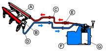
FIG #2
FIG#3
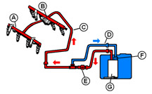
Semi-Returnless System (fig. 3) -- In semi-returnless systems, fuel travels a short distance outside the fuel tank to an underbody-mounted pressure regulator/fuel filter assembly. Returned fuel does not travel through the engine�s fuel rail, decreasing the amount of heat it�s exposed to.
A Fuel Rail
B Pulsation Damper
C Feed Pipe
D Return Pipe
E Filter
F Regulator
G Pump
Returnless System -- In a returnless system, the regulator is in fuel tank. Excess fuel returns directly to the fuel tank. The filter may be in the tank, inside the pump module. Environmental regulations have made the returnless fuel system necessary. It keeps fuel cooler, reducing evaporation and excessive hydrocarbon emissions.
The fuel system is divided into two parts, low pressure and high pressure. In all three types of systems, the high-pressure side begins at the fuel pump and ends inside the fuel rail. The low pressure side begins at the regulator fuel bypass port and ends at the fuel reservoir in the tank. Returnless systems are characterized by a single high-pressure line that runs to the engine compartment.
The main difference between the three systems is the location of the fuel pressure regulator. In return systems, the regulator is in the engine compartment (on or near the fuel rail) and in returnless and semi-returnless systems, it�s in or near the fuel tank.
Regardless of location, the fuel pressure regulator regulates system pressure by bypassing excess fuel back to the tank. In return and semi-returnless systems, proper diagnosis of pressure concerns requires testing and inspection of the regulator and verification that the pump or pump module is delivering adequate fuel. Inadequate fuel flow may be caused by clogged strainers or filters, rather than pump failure, especially if fuel starvation symptoms occur only at low fuel levels or during hot weather.
FIG#4
Fuel Pressure Regulator Operation
There are two types of Delphi fuel pressure regulators on GM vehicles, Universal Pressure Regulator (UPR) and Mini-Cartridge Regulator (MCP). GM uses regulators from other suppliers, too, but the designs are similar and operation is identical.
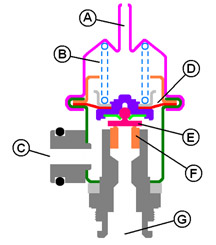
Universal Pressure Regulator (UPR) (fig. 4)
A Vacuum Port
B Spring
C Fuel Out
D Diaphragm
E Valve
F Seat
G Fuel In
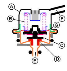
Mini-Cartridge Regulator (MCP) (fig. 5)
A Cover
B Spring
C Valve
D Seat
E Fuel In
F Fuel Out
G Diaphragm
FIG#5
The fuel pump and fuel pressure regulator work in concert to control fuel pressure supplied to the fuel injectors. At a given voltage, the fuel pump supplies fuel at a relatively constant rate to the pressure regulator. Unneeded fuel diverts back to the tank, to match fuel delivery to engine demand. Fuel flow from the pump varies strongly with voltage. If system voltage is low, the pump may not receive enough power to fully pressurize the system or supply the engine at high fuel demand conditions. Fuel pressure regulators are preset for a particular operating pressure during assembly, and are not adjustable.
Return System Operation
In most all return systems, the fuel pressure regulator contains a vacuum chamber that is connected to manifold vacuum and is separated from the fuel by a diaphragm and valve assembly. The diaphragm has fuel on one side and engine manifold pressure (vacuum) on the other.
All GM fuel pressure regulators contain a calibrated spring located in the vaccum chamber side. Fuel pressure in the fuel rail is regulated by pressurized fuel from the pump acting on the fuel rail side of the regulator�s diaphragm, pushing against the spring pressure and manifold pressure (vacuum) on the other side. When the combined force of vacuum on one side plus pressurized fuel on the diaphragm gets high enough to overcome spring pressure, the relief valve orifice opens, reducing rail pressure slightly by bypassing a controlled amount of fuel to the fuel tank. When an injector fires, it causes a slight pressure drop in the rail. In return systems with a vacuum hose connected to the regulator, vacuum applied to the regulator keeps the pressure difference (pressure drop) constant between manifold absolute pressure and supplied fuel pressure.
Returnless System Operation
Returnless systems operate similarly, but fuel rail pressure decreases slightly with increasing fuel demand. Fuel pressure does not vary with manifold vacuum because the regulator is referenced to atmosphere, not to manifold vacuum. Except for the lack of a vacuum reference, fuel pressure regulators in returnless systems work just like they do in return fuel systems. The calibration of the PCM is modified to look at changes in MAP and vary the pulse width of the fuel injectors to adapt to varying engine loads.
Fuel Pressure Regulator Common Problems
TIP: These conditions apply to return or semi-return systems.
Leaks -- Regulators can leak internally or externally. An internal leak is usually caused by a crack in the diaphragm. An internal leak can be diagnosed by removing the vacuum hose and checking for fuel seepage on the outlet tube or the vacuum line. Place a clear piece of vacuum hose over the vacuum orifice for a short period of time (15 � 30 minutes). If fuel rises up in the hose, the regulator is leaking and needs to be replaced.
Common customer complaints that suggest a leaking regulator are extended crank and fuel odor. More diagnostic tips will be given later.
Noise -- Regulator related noise may be system oriented or the regulator itself. Hold a stethoscope on the regulator and listen for the noise the customer is concerned about. If the regulator is noisy, replace it.
TIP: A noisy regulator may be improperly diagnosed as a noisy alternator.
Disconnecting the alternator is not a good test for isolating noise issues. System voltage will drop, which causes the fuel pump to create lower pressure, eliminating the fuel pressure regulator noise.
Temporarily disconnect the vacuum hose from the regulator if it has one, which slightly raises controlled fuel pressure. If the regulator has no vacuum hose, connect the fuel shutoff valve special tools listed in SI and slightly close either valve to alter controlled pressure. DO NOT fully close either valve when the pump is running, as regulator or pump damage could occur.
With either procedure, if the noise is gone, the problem is not the alternator. Be sure to reconnect the vacuum hose if it was disconnected.
TIP: A regulator that is noisy on one vehicle may not be noisy if placed on another vehicle. And a noisy regulator may be quiet for awhile when removed and inspected on the same vehicle.
Fuel Injectors
An injector operates on 12 volts and delivers fuel when opened. Voltage is supplied to the injector when the key is turned on. Some vehicles have the voltage side of the injector circuit connected to the fuel pump relay. Therefore the injectors will not receive voltage unless the fuel pump is energized. The PCM controls the ground circuit to complete the path for current to flow.
You may suspect an injector is not working if there is a misfire with a code and a dead skip, and the spark is good. Check for voltage to the injector and check that the PCM has the ability to pulse the injector on and off.
TIP: The recommended test for a complete electrical circuit to the injector utilizes a noid light. Simply disconnect the wire harness connector, plug in the noid light, and crank the engine. If the light flashes, voltage to the injector and the PCM�s ability to turn the injector on and off are good.
TIP: The noid light does not have the same resistance as the injector and may not draw the same current. A high resistance circuit may not affect the noid light as much as it would an injector.
Two causes of intermittent injector operation were covered in past TechLink articles: �fretting corrosion� in June, 2003 and injector partially restricted in December, 2002. If you suspect either of these conditions, refer to the TechLink article or a bulletin that advises you on how to test for these conditions.
TIP: If you perform a balance test to find a tricky injector misfire, be sure to use the kPa scale on your pressure gauge and not the psi scale.
Fuel Pumps
The fuel pump provides fuel flow and pressure to meet engine requirements under a wide variety of conditions. These functions must be met without creating undesirable noise, vibration, overpressure, or EMI/RFI in the vehicle.
FIG#6
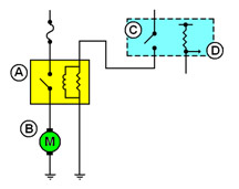
Typical fuel pump schematic (fig. 6)
A Fuel pump relay
B Fuel pump
C Fuel pump relay control
D Fuel level sensor signal
When the ignition key is turned on, the PCM sends voltage to the fuel pump relay and cycles the fuel pump for 2 seconds. If the PCM does not see ignition reference pulses, it turns the fuel pump off. Other inputs may also be involved on some vehicles.
TIP: If you have concerns about fuel pump operation, go back to the basics, check the schematic for the vehicle you�re working on, and understand how the system operates before you start replacing components.
TIP: In the fuel pump circuit, grounds are critical. Ground connections must be clean and tight.
A fuel pump is designed to operate on numerous fuel compositions in a global marketplace. The pump must deliver a specific volume and pressure required for each application. If the pump does not deliver enough volume, a pressure drop occurs and the vehicle will experience lean combustion during high fuel demand conditions. If the pump delivers too much flow, a larger current draw takes place and the fuel that travels through the system heats up and creates excessive hydrocarbon vapors.
Currently, there are three types of electric fuel pumps used in GM vehicles. They are the turbine, rollervane and G-rotor types. Although the pumping section of each of these pumps is different, the main purpose of the pump is the same -- to provide adequate fuel flow and pressure to the engine under all operating conditions. For diagnostic purposes, fuel pressure values are most important for quick and accuate fuel pump diagnosis.
TIP: Current draw readings on the vehicle are not an accurate indicator of fuel pump condition. There are numerous variables, outside the fuel pump, which can affect the accuracy of these readings. Electric fuel pump current values are typically not published for on-vehicle diagnosis.
FIG#7
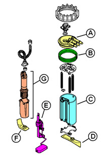
Modular Reservoir Assembly (MRA) (fig. 7)
A Cover
B Seal
C Reservoir
D Strainer
E Fuel level sensor
F Strainer
G Pump
FIG#8
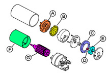
Typical Rollervane Pump (fig. 8)
A Inlet
B Impeller
C Ring (eccentric)
D Roller
E Rotor
F Magnets
G Armature
FIG#9
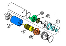
Typical G-Rotor Pump (fig. 9)
A Inlet body
B Impeller
C Gerotor assembly
D Magnet assembly
E Armature
F Brush assembly
Because the fuel pump is located in the fuel tank, quick visual checks may be difficult. To determine if the fuel pump is working at all, hook up the Tech 2 and a fuel pressure gauge and cycle the pump on a couple times. If fuel pressure readings are within specification, you know the pump is working. If there is no fuel pressure, check for a loss of voltage to the pump. Wiring can become corroded, loose or broken. Make electrical repairs according to SI.
If the pump runs when commanded on with the Tech 2 and you still suspect poor fuel pump performance, look for dirt or rust which could cause the pump to wear out prematurely.They can also cause the pump check valve to stick open, leading to hard starting, especially when the engine is hot. Rust is always caused by water, either from the fuel source, by condensation or by ingestion of water by the fuel system. If the vehicle is used under extreme operating conditions (such as off-road), water and dirt may be ingested through the canister vent system.
Fuel lubricates and cools the pump. Driving the vehicle frequently with a very low fuel level in the tank can starve the pump of lubrication and cooling, which can accelerate wear and condensation, two causes of pump problems.
If you replace a pump that has failed due to dirt or corrosion, clean out the fuel tank and lines, to avoid the same damage to the new fuel pump. Also, replace the fuel filter and clean or replace the pickup screen. Contamination on the screen cannot be seen without magnification. Newer vehicles with a pump module usually have two screens, one on the outside of the module and one on the pump inside the module. Both screens may block, but the screen on the inside of the module is not serviceable. So the module must be replaced even if the pump itself is still functional. Dirt visible inside the module �bucket� is an indication that both strainers may be blocked. If contamination is in the fuel tank, it�s most likely to be in other locations in the fuel system. It�s a good idea to check for contaminants in the fuel rail and fuel lines also.