For those interested in making the 3500 & 3900 V6 compatible for use in pre 05 vehicles requireing a 7x reluctor signal, without the use of an external sensor/wheel setup or having to take on the monumental task of trying to graft in the 05 and up computer and required sensors etc. I have just received the first laser cut of the 7x ring to replace the new design found on the newer engines.
I will not have the necessary time to attempt to install it and wire up the Turbo Grand Prix ecm to check for appropriate ignition fireing until ~17th of this month during which time I will also have to fabricate a spacer for proper positioning of the sensor.
So far the apparent necessary improvements are the stretch relief notches in internal diameter, the outside perimeter has a few rough areas (geartooth like marks) that need to be smoothed out and the laser break away (completion) point needs to be tuned and moved so that it does not leave the slight step at the begining of one of the nothces which is supposed to be an edge with a 90 degree drop. Other than that it looks good.
For those who are interested in investing in one so that it's available for use when you get your hands on the 3900 or readily available 3500 like me, I expect the cost with the adaptor for the crank sensor to be ~$50-60 maybe lower depending on how many are ordered, the initial costs up to where I am now for this one ring was $150 and I don't expect the adaptor for the sensor to be that big a deal once I provide the plans for it.
PM me if you would like to be added to the count and once this is tested and proven and tallied up I will get back with you on what the actual cost will be and can setup purchasing as "Buy now" on Ebay.
The ring is .244 inches thick, the magnetic button at the end of the sensor is .198, it doesn't look that close with the "eye" ruler but it is so that's another change that may need to be added to the list. I'll also see if I can get my hands on some kind of oscilloscope to check for an accurate and consistent signal. The sensor pickup needs to be right at .050 from the ring, the center point in the .020 - .070 range. Deviating to much from it will intensify or weaken the voltage output according to the info from the GM manual I have.
IP: Logged
07:23 AM
Jun 5th, 2006
Fierobsessed Member
Posts: 4782 From: Las Vegas, NV Registered: Dec 2001
So far I have sent a request to the machinist for costs consideration for the following modifications:
going to 5/16" thick from 1/4" incorporating a .130" step in one side to accomodate the one on the crank backing surface which might throw the ring off center of the sensor button.
Increasing the inner diameter so that the ring can be slipped on by hand. and shortening the notch depth from .25" to .21" to match that on the 3400 crank being used for reference.
I have figured out an excellent method of securing the ring to the crank if I can find the supplies.
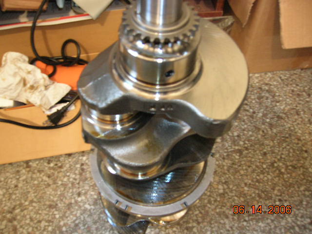
I'm getting there, I'll have to have the ring inner diameter increased and I have an oscilloscope now to test it once it's all bolted down at the end of the month. I did a little research today and think I ended up with a steel crank, GM parts lists two for the 3500, I have #12577484 (7484 is all that is stamped on it of the whole number) which lists for over $400 and weighs 49 lbs, the other crank that apparently did not come available until 2006 according to their listing #12568259 weighs 45 lbs and list for around $340. The confusion is that their power train data pages list a steel crank for the early 3500, but their 2006 vehicle release description states that the Buick SUV gets the steel crank, my suspicion is that what they may have meant is; now that we have started making a cheaper crank the SUVs will get the steel crank and the passenger cars will get the cast, that's the only way I can make sense of it. Unless there is a cost effective way to make the steel crank cheaper and lighter than the cast.
The 3400s crank weighs 37 lbs
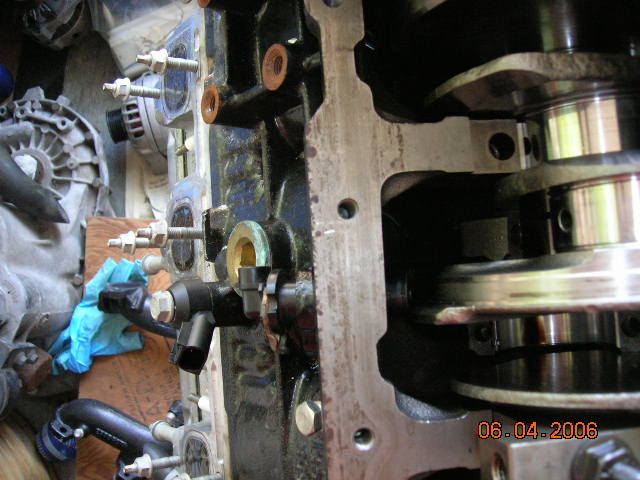
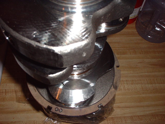
Anyway here is what I have so far:
Using someone elses camera that's why it's not clear
[This message has been edited by Joseph Upson (edited 06-15-2006).]
IP: Logged
02:41 PM
1fastcaddy Member
Posts: 618 From: Hays, Kansas Registered: Oct 2004
Nice progress, wonder if these new motors can handle any boost? Might be something to look into. These have the M6 bolt pattern correct? thanks
With a steel crank and forged rods stock the question is how much can the pistons handle, it's the traditional 60 degree V6 bolt pattern, I'm hoping a local salvager that has 4 3900s will take $300 cash and my 0 miles 3500 in a trade for one.
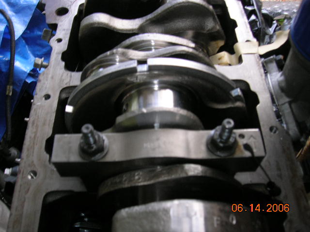
Current status on the crank trigger for the engine with the newer style crank ring and signal. I'm also working on a way to convert the large bore throttle body to manual operation so that it can be retained. The crank is in the engine and once I finish wiring up enough of the ECM inputs and modifying the oil pan for oil return from the turbos I can button it up and test it.
IP: Logged
06:11 AM
Fierobsessed Member
Posts: 4782 From: Las Vegas, NV Registered: Dec 2001
I'm going to need one of these... Suppose since its a steel crank, a few quick stitches with the tig might do the trick for securing it.
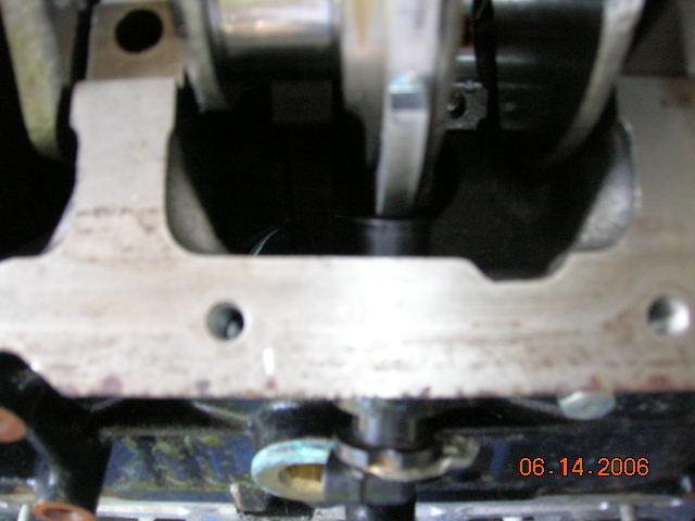
I doubt you would need to TIG it in place since the original was pressed on and GM trusted that. I actually had to heat the ring in order to get it to slip on to the mounting surface and that's a good thing since once it cooled it tightened down, so much so that when I had to remove it for repositioning, it didn't come off without a fight, the two set screws are added security located 180 degrees from each other. I believe drilling a little sink for the set screws to seat into and applying lock tite to them is all that would be necessary since they would either have to be sheared or the ring severely stretched in order for it to move from its location.
TIG welding on the first 60 degree steel crank would be uncivilized, it's to pretty for that.
Preliminary oscilloscope test completed on the ring. Next will be to connect the ignition system and see if the spark occurs like it's supposed to. The bottom wave form represents the ring, the top wave is an example. I believe the wave gets narrower and taller with speed, I'm working with cranking rpm.
IP: Logged
05:41 PM
Oct 21st, 2006
Luke Member
Posts: 467 From: Toronto, Ontario, Canada Registered: Nov 2005
Put me down for one when youre done, Ive got a 3500 with 1k km on it just begging to replace the 3400 thats in my engine bay, the reluctor and tb are my current 2 financial/ technical hold ups.
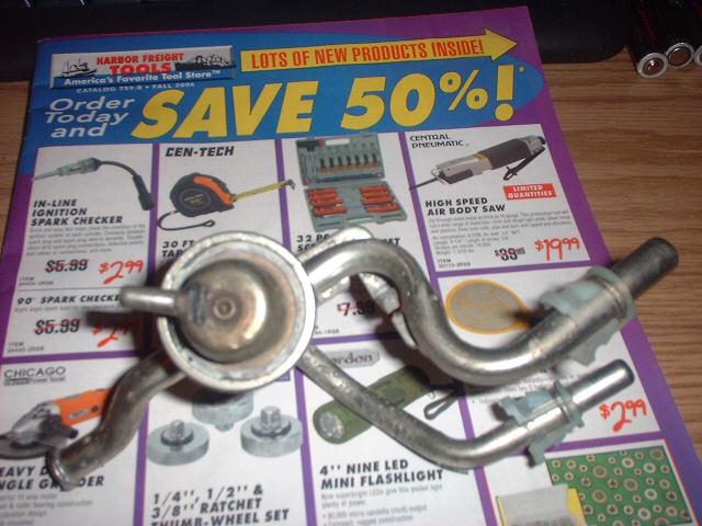
I'm working on the throttle body also and instead of running all over town in an effort to find the right raw materials for the job I think I'm going to order a batch from McMaster Carr and be done with it. I have already solved the returnless fuel rail issue which I wanted to keep for it's benefits, an adjustable regulator from an 8100 fuel rail which incorporates an input, output and return line all in one assembly;
IP: Logged
12:43 PM
1fastcaddy Member
Posts: 618 From: Hays, Kansas Registered: Oct 2004
At the moment I'm putting a turbo back on my daily driver which has been down for about 3 and a half months. Later tonight I'll be soldering up the ALDL interface so I can confirm by values on the computer screen that I'm connecting sensors to the 727 computer properly and hopefully Monday I'll be able to perform the spark test.
It works! however I still need to connect enough to the engine to actually run it on the stand briefly to make sure the computer can make timing adjustments for it since the make shift SES light I connected to it is not flashing when the A and B terminals are grounded on the 727 ECM. The fuel pump relay cycles on and off when power is supplied and the IAC motor adjusted the pintle all the way out of the housing so it's working, I haven't modified the throttle body yet so it was not in a housing. The spark is very strong as can be seen in the picture jumping between two plug terminals on the coil.
Just keeping the thread alive, it will be a few more months before I can get a break to finish, it is further along than this and currently on a cradle bolted to the F40 tranny