Can someone with a lot more electrical savvy than I, please take a look at this schematic, and tell me if it will work. In particular, the switch bothers me.
David Breeze
------------------ Pantera Rebody Kits
IP: Logged
03:27 PM
PFF
System Bot
opm2000 Member
Posts: 1347 From: Versailles, Ky USA Heart of the Bluegrass Registered: Dec 2000
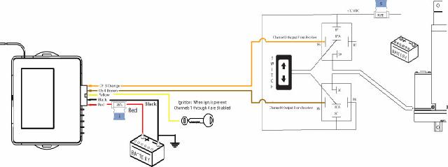
I have the remote control box, as shown above. The Tech guy at Spal said if you don't want a switch, just make it a ground. Makes sense. But I do want a manual switch. The Tech guy said just a plain old up/down switch, that provides ground when pushed will be fine.
I guess I don't see how the circut gets completed when using the remote, if the switch isn't providing ground.
David Breeze
IP: Logged
03:32 PM
May 10th, 2006
PaulJK Member
Posts: 6638 From: Los Angeles Registered: Oct 2001
At first glance, it seems to me that the switch needs to be a 3-pole switch and the 3rd pole needs to be a ground. The center pole on the relays duplicates one of the others, but I don't remember which one .
{bump}
IP: Logged
02:27 AM
opm2000 Member
Posts: 1347 From: Versailles, Ky USA Heart of the Bluegrass Registered: Dec 2000
Actualy, I dont think you need a switch. Normaly the relays connect 30 and 87, so the LAM is normaly seeing 12v on both lines = nothing. When you throw one relay, you are disconnecting that 12V, so its line is dead. Now if you had that relay's 87A pole on ground, rather then being dead, it would be ground, the other line still having 12V would turn the motor on one direction.
With it wired as in that pic nothing would happen and the switch would be useless.
The other thing to do if you want the switch to prevent operation is to tie the 87A poles together, then put the switch between ground and one of them
[This message has been edited by 86GT3.4DOHC (edited 05-10-2006).]
IP: Logged
09:46 AM
opm2000 Member
Posts: 1347 From: Versailles, Ky USA Heart of the Bluegrass Registered: Dec 2000
This diagram sounds similar to what you just described, except it only uses a switch, and doesn't use the remote controller. Might be best to do the first set up this way. All I know about electricity is that Mr. Electricity comes in on one wire, and goes out on the other wire...sad, isn't it ?
IP: Logged
11:00 AM
PaulJK Member
Posts: 6638 From: Los Angeles Registered: Oct 2001
The alarms I 've used will provide a ground (-) through the designated wire when you press the button on the remote. In your diagram, the Orange and Brown alarm wires do nothing until you press the remote; then the wire matching the remote button gives a (-). Maybe your remote has (1) button/channel output that activates the Orange wire and another buttonchannel output that activates the Brown one. The alarm installer's manual should tell you for sure what each output provides. The good news is that it can only be a (+) or a (-)
[This message has been edited by PaulJK (edited 05-10-2006).]
IP: Logged
10:07 PM
May 11th, 2006
opm2000 Member
Posts: 1347 From: Versailles, Ky USA Heart of the Bluegrass Registered: Dec 2000
Well, yes, you'r correct. The remote manual has channels 3 & 4 ( orange & brown wires in top schematic ) listed as negative outputs, and there is a 3 button & 4 button on the remote controller which you hold in your hand.
What gets me here is I'm trying to understand this stuff. The last link/schematic I can pretty well follow.
Then I've found about three flavors of the first schematic. In one of them, the switch is listed as a 5 prong switch. The remote manual shows this as a reversing circut, and says it is important to use a switch which is grounded at rest. And then there is the one at the top of this page, and the tech guy says just a plain old switch.
Maybe I should ditch the actuators and just use a 3' stick
IP: Logged
06:10 AM
Lambo nut Member
Posts: 4442 From: Centralia,Missouri. USA Registered: Sep 2003
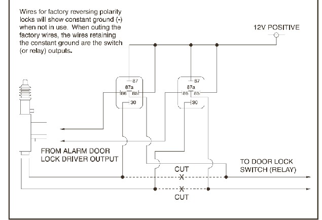
This is basically what you're doing although it's for a door lock instead of an actuator. The only difference is what you're actuating but they are both reversing polarity devices. That is, to go one way the wires are hooked up +/- and to go the other way the wires are hooked up -/+. Read the note at the upper left corner of the drawing that reads "Wires for factory reversing polarity locks will show constant ground when not in use"
Don't feel bad, I've gone through the same head scratching several times.
John Stricker
PS: LINk to tons of ways to wiring up relays in automotive applications. Nice reference.
IP: Logged
09:39 AM
opm2000 Member
Posts: 1347 From: Versailles, Ky USA Heart of the Bluegrass Registered: Dec 2000
This is essentially like the first schematic, and the last on put up by jstricker....I think, except we show going to a constant ground, instead of a switch
I don't see how putting a switch in place of the two constant grounds will work. Maybe I just don't grock the switch (figure that one out). Does the switch maybe show ground to both wires when at rest, and when you toggle the switch, does it just take one wire out of the picture, and provide the ground to the remaining wire?
That 3' stick is looking better all the time
IP: Logged
12:13 PM
PFF
System Bot
opm2000 Member
Posts: 1347 From: Versailles, Ky USA Heart of the Bluegrass Registered: Dec 2000
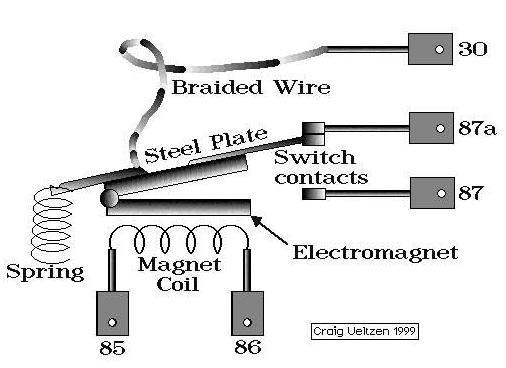
OK, first let's look at the inner workings of the standard Bosch type relay.
You have five terminals but the first two we're going to look at are 85 and 86. As you can see, these are the electromagnetic contacts that pulls in the relay. 12V+ and a ground respectively to these two terminals will cause the relay to pull in and close the circuit between 30 and 87. Whenever there is no power to these terminals, the circuit is closed between 30 and 87a.
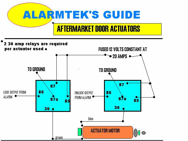
Now scroll up or print out the diagram I posted as that's what I'm going to refer to. No matter what, 85 and 87 are hot when you have power to the actuator circuit. When no switches are depressed and there is no current able to flow through 85 and 86, the relays have the circuit closed between 30 and 87a. On the two relays, the wire from 30 goes to the actuator. So what happens when we press some buttons.
Well, let's say the left relay is for UP and the right is for DOWN. We push the button on the remote that will complete the ground to the left relay and that pulls the relay in making continuity between pin 30 and 87. Because 87 is hot, it makes 30 hot. Since we have a constant ground on 87a, the circuit to the actuator is complete and the actuator goes up.
Now we push the button on the remote that completes the circuit to ground terminal 86, it pulls the right relay in and since we have a constant ground between 87a and 30 on the left relay, the actuator goes down.
Now it gets tricky. For a manual switch, you need either power window type crossover switch or some fancy wiring with two standard switches. Here's what the inside or a typical power window switch looks like schematically.
As you can see the switch has 5 poles. 2 of them (1 and 2) go to the motor in the diagram but for our purposes, we're going to send it to 87a on each of our two relays. The other three are connected pins 3 and 5 to a ground and pin 4 to a 12V+ source. Now when the switch is neutral, both pins 1 and 2 are connected to the ground pins, 3 and 5, and in turn that makes a ground to the 87a terminal which, TADAAA, gives us a constant ground. When we press the button UP as shown in the diagram, it sends 12V to pin 1 which will make 87a hot in the left relay, and since we have a ground through the right relay and pin 2 on the switch, the actuator goes up. When we press the button DOWN, that makes pin 2 hot and since we have a constant ground through pin 1, the actuator goes down.
I know this is kind of hard to visualize through words, but I think if you print out the three circuits and sketch them out as they are to be wired, you'll see how they work.
John Stricker
IP: Logged
11:04 PM
tjm4fun Member
Posts: 3781 From: Long Island, NY USA Registered: Feb 2006
I think alarm engineers are the ones that flunked out. if I understand this, this is in english how this is supposed to work: Actuator can move out or in push ch3 button actuator moves in one direction (say out for the heck of it) push ch4 button actuator moves in opposite direction (say in for the heck of it)
I am taking a wild guess and saying the swithc is the manual override funcion to move the actuator in one or the other direction.
Electrically here is what happens: (ref the pic OPM2000 posted called alarmtek's guide) no channels selected, the blue actuator wire connected to pin 30 of the unlock relay (normally called the common pole of a switch or relay is at ground thru pin 87a. same is true for the green wire thru the unlock relay, same points. you press a button to lock: the lock relay picks, which now connects the green wire to 12v thru 30 and 87. the blue wire and unlock relay is still not energized, so it supplies the ground and the actuator moves in one direction. usually that relay will drop after a certain amount of time, as the actuator is fully extended/retracted. you press the other button to unlock: the unlock relay picks, which now connects the blue wire to 12v thru 30 and 87. the green wire and lock relay is still not energized, so it supplies the ground and the actuator moves in one direction.
simple so far. the real problem is how do you properly hook up the override switch? There are 2 ways. either parallel the relays with a heavy duty switch, which is sort of stupid, or let the switch control the inputs. since you don;t want to potentially damage the alarm module, I would get 2 push button double throw switches and install it on the 2 lines from the module as follows:
orange _____________0 (Normallyclosed ) ground ____________0 \________________ to relay pin86 (normally open )
brown _____________0 (Normallyclosed) ground ____________0 \________________ to relay pin 86 (normally open)
this way, you can select what you want, and if the button is not pressed, the module works as it should.
Hope I didn;t confuse you totally now.
[This message has been edited by tjm4fun (edited 05-12-2006).]
IP: Logged
11:50 PM
Lambo nut Member
Posts: 4442 From: Centralia,Missouri. USA Registered: Sep 2003
If I could have found your first picture of the innerds of the relay, I might have given somewhat of an explanation earlier, but nothing as detailed as this, instead of just interjecting a useless remark. I was lookind for something like this in my Digi key, and Mouser books, but neither gave me the detail you have here. I was following the thread from the beginning, hoping to help, but kind of gave up when I could not readily find what I was looking for. Excellent write up.
Kevin
IP: Logged
11:53 PM
May 12th, 2006
Lambo nut Member
Posts: 4442 From: Centralia,Missouri. USA Registered: Sep 2003
Good description there, jstricker. I'd found that same 5 pole switch diagram last night and it then began to make sense.
What I didn't realise was tht we are really running two completely seperate circuts: one using the remote as the switch, a 12 volt source, and the two functioning relays. And a second completely seperate circut using the 5 pole switch, a second 12 volt source and going thru the relays, but not making the relays move (or function).
I needed to see how a 5 pole switch could be used in two ways as well: one where it just provides a constant ground at rest and one leg grounded & one leg open. And one way where a 12 volt source is provided to the switch, both legs are grounded at rest, and one leg is grounded and one sends out 12 volts when the switch is depressed.
I think tjm4fun has a point. The manual switch is going to have a high amp load running thru it all the time it's activated. The travel rate of linear actuators is not very fast. I allways thought one of the big benefits of using relays was to keep the heavy electrical loads out of the manual switches, and to keep the heavy loads running thru the relays.
Now I'm going to struggle with how tjm4fun is saying to wire switches in the two incoming wires from the module. I think what he is saying is that this method would use the relay system to activate things, and not just pass a second circut thru them.
Lambo Nut is right about that 5 amp fuse, I believe. The standard rating for one linear actuator is a 10 amp fuse. What has been unsaid sofar is that I am actually running two linear actuators at the same time. I will run two sets of wires from the 30 leg of each relay, one set to each of the linear actuators. The Spal manuals seem to think this is ok but vaguely mention using a 20 amp fuse.
IP: Logged
06:35 AM
jstricker Member
Posts: 12956 From: Russell, KS USA Registered: Apr 2002
One thing you have to remember is there is a very good reason for wiring them the way the diagram I posted shows and that is redundancy. If something happens to the relays, or the power to them, or whatever, the manual switch will still move the actuator without any action being taken by the relays themselves. That's the real reason for the manual switch anyway, as a failsafe. You could, of course, just wire up the switches to go to ground and wire that to the relay terminal to pull in the relay. But if you do that, and the relay fails, you're stuck with no way to make things work.
John Stricker
quote
Originally posted by tjm4fun:
I think alarm engineers are the ones that flunked out. if I understand this, this is in english how this is supposed to work: Actuator can move out or in push ch3 button actuator moves in one direction (say out for the heck of it) push ch4 button actuator moves in opposite direction (say in for the heck of it)
I am taking a wild guess and saying the swithc is the manual override funcion to move the actuator in one or the other direction.
Electrically here is what happens: (ref the pic OPM2000 posted called alarmtek's guide) no channels selected, the blue actuator wire connected to pin 30 of the unlock relay (normally called the common pole of a switch or relay is at ground thru pin 87a. same is true for the green wire thru the unlock relay, same points. you press a button to lock: the lock relay picks, which now connects the green wire to 12v thru 30 and 87. the blue wire and unlock relay is still not energized, so it supplies the ground and the actuator moves in one direction. usually that relay will drop after a certain amount of time, as the actuator is fully extended/retracted. you press the other button to unlock: the unlock relay picks, which now connects the blue wire to 12v thru 30 and 87. the green wire and lock relay is still not energized, so it supplies the ground and the actuator moves in one direction.
simple so far. the real problem is how do you properly hook up the override switch? There are 2 ways. either parallel the relays with a heavy duty switch, which is sort of stupid, or let the switch control the inputs. since you don;t want to potentially damage the alarm module, I would get 2 push button double throw switches and install it on the 2 lines from the module as follows:
orange _____________0 (Normallyclosed ) ground ____________0 \________________ to relay pin86 (normally open )
brown _____________0 (Normallyclosed) ground ____________0 \________________ to relay pin 86 (normally open)
this way, you can select what you want, and if the button is not pressed, the module works as it should.
Hope I didn;t confuse you totally now.
IP: Logged
07:52 AM
jstricker Member
Posts: 12956 From: Russell, KS USA Registered: Apr 2002
They actually show two 5 amp fuses, one to the receiver and one on the actuator and I saw that as well. That must be a really efficient actuator or it's not lifting anything. Most power window circuits take at least a 20 amp and most power lock/door circuits take a 30 which, BTW, reminds me. There is some obscure NHTSA or NTSB regulation somewhere that specifies that door locks and windows have to be on automatic reset circuit breakers so that it's harder to get trapped inside a vehicle. I helped a guy get his "kit" '34 Ford inspected and issued a new VIN and when the inspector looked at it he saw it had power windows and made him replace the fuses with ATC Sized breakers before he'd pass it. Only reason I helped is the Roadster has a salvage title and to get it back to a highway it will have to be inspected so I wanted to see what all was done during the inspection.
John Stricker
quote
Originally posted by Lambo nut:
I follow now, and see both tjm4fun, and John's points. I don't think the 5 amp fuse in the first diagram is going to last very long though.
Kevin
IP: Logged
07:58 AM
opm2000 Member
Posts: 1347 From: Versailles, Ky USA Heart of the Bluegrass Registered: Dec 2000
Both points are well taken jstricker. The manual switch is a backup to a failed relay or remote control unit, I just never thought of it as such. And the 5 amp fuses they show are way out of whack.
If you look at the second page of the above .pdf link, SPAL shows a basic switch controled circut with a 10 amp fuse, and in the text says it will handle two linear acatuators with a 20 amp fuse.
So, getting back to using the very first circut in this thread, with a 5 prong switch connected to both 87a legs, ground, and a 12 volt source, I suppose another 20 amp fuse should be put in between the battery and the switch.
Amazing that such vague circutry would be handed out by the vendors. Amazing that the tech guy really gave the wrong answer when asked about the switch. Pennock's rocks


 .
.