Pennock's Fiero Forum
  Technical Discussion & Questions - Archive
  A few Q's about electrical wiring...

T H I S   I S   A N   A R C H I V E D   T O P I C
  

Email This Page to Someone! | Printable Version


A few Q's about electrical wiring... by Fie Ro
Started on: 03-04-2006 04:26 PM
Replies: 9
Last post by: watts on 03-06-2006 10:57 PM
Fie Ro
Member
Posts: 3735
From: Soest, The Netherlands
Registered: Sep 2001


Feedback score: N/A
Leave feedback


Total ratings: 132
Rate this member

Report this Post03-04-2006 04:26 PM Click Here to See the Profile for Fie RoSend a Private Message to Fie RoDirect Link to This Post
I have a few electrical questions because I suck at understanding electrical wiring and schematics...I can stare at it for an hour and still dont get it what it does!
So I need some input on the following:
1.
I am going to move the battery to the front, what is the best way to wire it? I am guessing ground near the battery, 1 +wire to the rear (junction block) and 1 seperate +wire to the starter to stay safe.....is this the best setup? And how do I wire the alternator to the battery? > connect it to the rear junction block or a seperate wire to the battery?
I have a roll of wire that may be usefull but I am not sure ; it is stamped with "10mm2" diameter and is used as a heavy duty 230V cable but I am not sure if thats suited for this application, looks the stock wires are thicker...
2.
I still need to rewire the window motors to my "new" switches. This thread convinced me to do it the-relay-way so I got some relays but I am not sure yet how to wire them because they came without instructions. found this info while looking at simmilar relays:

------
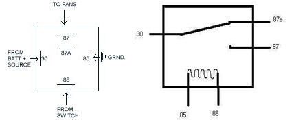
Pins 85 & 86 are the relay coil. Pin 30 is the power input, Pin 87a is the Normally Closed output, and Pin 87 is the Normally Open output.
When power & ground are applied to the coil, the "switch" inside the relay is pulled down from the Normally Closed contact to the Normally Open contact.
-------
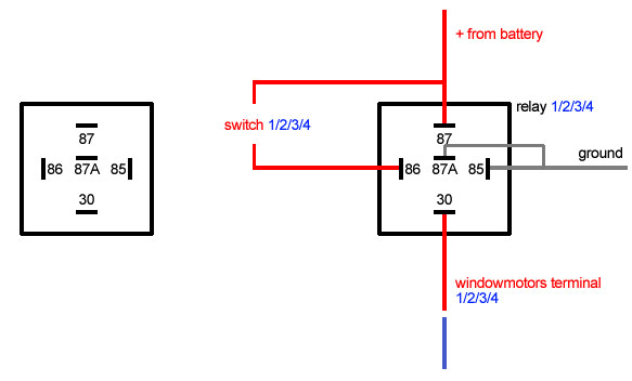
Here is is the layout of my relays, and after staring at it for hours huh.. I wonder......could this setup work?

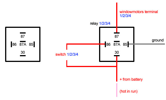
its 4 switches and 4 relays in total (up+down left and up+down...right).

3.
I want to wire a cluster of about 7 or 8 leds to 12V. I already know I will need some kind of resistor but what do I need and how do I have to wire all of it? These are generic 5mm leds 2.1V...

------------------

1987GT getting 'concept GTR' treatment...1-body buildup 2-interior buildup

IP: Logged
PFF
System Bot
Ken_86gt
Member
Posts: 574
From: WILLIAMSBURG
Registered: Jan 2004


Feedback score: (1)
Leave feedback

Rate this member

Report this Post03-05-2006 09:22 AM Click Here to See the Profile for Ken_86gtSend a Private Message to Ken_86gtDirect Link to This Post
I'll try to answer your power window question. From looking at the wiring diagrams for the window system: http://www.euronet.nl/users/fo_elmo/fiero15.pdf

It looks like you need to alter your design slightly. Using the Left window as an example 87A should go to ground using the BLK wire on both relay, pin 30 DK BLU on one relay and BRN on the other, 87 to 12V on both. Your connections to 85 an 86 for the switch and ground look right.

I havn't done this myself.

IP: Logged
Ken_86gt
Member
Posts: 574
From: WILLIAMSBURG
Registered: Jan 2004


Feedback score: (1)
Leave feedback

Rate this member

Report this Post03-05-2006 09:39 AM Click Here to See the Profile for Ken_86gtSend a Private Message to Ken_86gtDirect Link to This Post

Ken_86gt

574 posts
Member since Jan 2004
The remote battery- many people just connect the 12V wire to the original battery wire, sometimes at the starter, and then no other wiring changes need to be made. You can ground the battery to the frame. If you do that you should probably add another ground wire between the engine and the frame- not the sub cradle. You could also run the ground wire back to the engine, and for good measure add another ground to the frame anyway.

As for the size of the wire, I don't know what you have there. The voltage rating isn't very important in this case, its how much current it can carry. The bigger diameter the more it can carry (in general). The wire size should be at least as big as the original, preferably larger. The longer the wire the more voltage drop you will get.

IP: Logged
Ken_86gt
Member
Posts: 574
From: WILLIAMSBURG
Registered: Jan 2004


Feedback score: (1)
Leave feedback

Rate this member

Report this Post03-05-2006 09:53 AM Click Here to See the Profile for Ken_86gtSend a Private Message to Ken_86gtDirect Link to This Post

Ken_86gt

574 posts
Member since Jan 2004
Your LEDs. If you put 6 or 7 in series, maybe you could get away with no resisters. When the engine is running there is usually about 13.5 volts at the battery, which would be 2.25 volts across 6 or 1.93 across 7. Otherwise you would need to create a voltage divider. If you need to be able to turn the LEDs on individually you will need a voltage divider. Post if needed.
IP: Logged
Fie Ro
Member
Posts: 3735
From: Soest, The Netherlands
Registered: Sep 2001


Feedback score: N/A
Leave feedback


Total ratings: 132
Rate this member

Report this Post03-05-2006 04:37 PM Click Here to See the Profile for Fie RoSend a Private Message to Fie RoDirect Link to This Post
Thanks! I think you are right about the relays 87A to ground because they have to switch polarity for the motors to turn the other direction...... so they both are grounded until one of both switches/relays switch + either for up or down...
Hope I get it now, is this the right setup?
\

Your comments on the battery setup also make sense, looks it will be battery + > starter > junctionblock. My engine is already grounded to the chassis with a big strap. Can I wire the alternator directly to that rear junction block?

Leds: yes I hoped it was possible to wire them the easy way... I have ideas about using 6 till 9 leds but I'll try to stick to 6 now to keep it easy. They will be all on or all off. Thanks for all the help

IP: Logged
RCR
Member
Posts: 4397
From: Shelby Twp Mi
Registered: Sep 2002


Feedback score:    (7)
Leave feedback


Total ratings: 102
Rate this member

Report this Post03-05-2006 06:17 PM Click Here to See the Profile for RCRSend a Private Message to RCRDirect Link to This Post
For the LEDs, connect two strings of 3 in parallel. Figure your voltage to be around 14V from the alternator with the car running. Each string will drop about 6V, so the resistor (one in each string) will drop about 8V. You probably want about 20mA through the LEDs to make them nice and bright (although it will depend on the LEDs). Take your 8V drop and divide it by your current, 0.020A and that will give you your resistor value, 400 Ohms. 390 and 430 are standard values. Use the 430 to be safe.

Bob
PS I'd use an H-bridge relay for each window.

IP: Logged
watts
Member
Posts: 3256
From: Coaldale, AB, Canada
Registered: Aug 2001


Feedback score: N/A
Leave feedback


Total ratings: 117
Rate this member

Report this Post03-05-2006 11:46 PM Click Here to See the Profile for wattsSend a Private Message to wattsDirect Link to This Post
For your power window relays.... I did it using two relays, and two push buttons per window.

https://www.fiero.nl/forum/Archives/Archive-000001/HTML/20060206-2-062039.html

IP: Logged
86GT3.4DOHC
Member
Posts: 10007
From: Marion Ohio
Registered: Apr 2004


Feedback score: N/A
Leave feedback


Total ratings: 306
Rate this member

Report this Post03-05-2006 11:54 PM Click Here to See the Profile for 86GT3.4DOHCSend a Private Message to 86GT3.4DOHCDirect Link to This Post
Just remember red + black = boom

looks like you got all your questions taken care of

IP: Logged
Fie Ro
Member
Posts: 3735
From: Soest, The Netherlands
Registered: Sep 2001


Feedback score: N/A
Leave feedback


Total ratings: 132
Rate this member

Report this Post03-06-2006 10:55 AM Click Here to See the Profile for Fie RoSend a Private Message to Fie RoDirect Link to This Post
 
quote
Originally posted by watts:
For your power window relays.... I did it using two relays, and two push buttons per window.
https://www.fiero.nl/forum/Archives/Archive-000001/HTML/20060206-2-062039.html

Yeah, me too....lookie at the link I posted in my first post, its the same as yours
Your thread convinced me to wire it that way....thanks.

IP: Logged
watts
Member
Posts: 3256
From: Coaldale, AB, Canada
Registered: Aug 2001


Feedback score: N/A
Leave feedback


Total ratings: 117
Rate this member

Report this Post03-06-2006 10:57 PM Click Here to See the Profile for wattsSend a Private Message to wattsDirect Link to This Post
 
quote
Originally posted by Fie Ro:
lookie at the link I posted in my first post, its the same as yours

Haha... OOPS!

Never even clicked the link.

IP: Logged


All times are ET (US)

T H I S   I S   A N   A R C H I V E D   T O P I C
  

Contact Us | Back To Main Page

Advertizing on PFF | Fiero Parts Vendors
PFF Merchandise | Fiero Gallery | Ogre's Cave
Real-Time Chat | Fiero Related Auctions on eBay


Copyright (c) 1999, C. Pennock