This subject is one that seems a little understood, so this is an attempt to explain it. I won’t be able to cover the entire subject in this post, but I will continue to post here until I feel the subject has been covered.
Bump steer is change in toe angle, caused by up and down movement of the suspension. Anything that causes change in toe, including chassis roll will be felt.
Bump steer is a function of; the relative position of the upper and lower ball joints, and the inner and outer steering rack ball joints. Normality can only move the position of the inner ball joints, so that’s is where bump steer is normally corrected. The rack mounts on racecars are adjustable for that reason.
Many production cars, including all year Fieros suffer from some bump steer. Almost all cars can be bump steer corrected, including Fieros, and this is how to do it.
You will need to be able to measure the actual bumps steer in your actual suspension system. General info about exactly where to reposition the rack will not be accurate. Very small movement of the rack will result in surprisingly large changes in bump steer.
To measure bump steer, you will need to remove the springs, and reassemble the suspension with out the tires. The car should be on jack stands in a way that allows you to move the control arms through their full range. You will need a reference line on the floor, parallel to the chassis centerline, at the tires contact point. You will also need a piece of square steel tubing clamped to the brake rotor, parallel to the floor. Bump steer will be visible by sighting down, so that relative parallelism between the steel tube, and the reference line on the floor is clear. By moving the control arms up and down, any bump steer will be seen. The extreme limits are not too important, but the point near normal ride is critical.
I will continue this soon. Questions so far..??
IP: Logged
01:34 PM
PFF
System Bot
SaLvAgEd Member
Posts: 973 From: Knoxville, IA Registered: Mar 2004
this is mostly front bumpsteer, with a steering rack, but mostly applies to rear bumpsteer also this is so much easier to explain graphicly. maybe someone can make a "bumpsteer gif" to show what causes this. like yellow said, if you took the springs out, you can swing the suspension thru its movement range, and watch the wheel turn in & out. tie-rod length & mounting height is the key to reducing bumpsteer. longer tie-rods make a smaller change as they swing up & down if they are on a different plane than the control arm. this is what the "bumpsteer kit" does. having tie rods the same length and mounted on the same plane with the control arm is an ideal setup - but, thats impossible, because there is no room - the tie rod end would be in the tire.
IP: Logged
02:43 PM
Yellow-88 Member
Posts: 454 From: Coventry CT. Registered: Feb 2005
this is mostly front bumpsteer, with a steering rack, but mostly applies to rear bumpsteer also this is so much easier to explain graphicly. maybe someone can make a "bumpsteer gif" to show what causes this. like yellow said, if you took the springs out, you can swing the suspension thru its movement range, and watch the wheel turn in & out. tie-rod length & mounting height is the key to reducing bumpsteer. longer tie-rods make a smaller change as they swing up & down if they are on a different plane than the control arm. this is what the "bumpsteer kit" does. having tie rods the same length and mounted on the same plane with the control arm is an ideal setup - but, thats impossible, because there is no room - the tie rod end would be in the tire.
Yes nice addition. The rear of a pre-88 is the front end from a front wheel drive car. The rear tie rods inner end is like the inner rack ball joint of an actual steering rack.
I’ve done a very interesting pre-88 rear end prototype that I hope to show at this years Kick Hill Farm swap meet. It matches the 88 front geometry exactly.
IP: Logged
03:04 PM
Yellow-88 Member
Posts: 454 From: Coventry CT. Registered: Feb 2005
I have been surprised to find the amount of bump steer varying a good bit between identical cars. Worn parts can have a profound effect on the amount of bump steer present, as can different caster settings. Having said that, it would be wise to be sure that everything is in good order before you consider moving the steering rack. To move forward with this, lets assume that you are working with the final configuration of parts and caster settings that will use.
At this point be very aware that repositioning the steering rack is not to be taken lightly. DO NOT consider these next steps without a full understanding of the seriousness of modifying your steering components.
To reposition the steering rack you will need to remove the factory installed “weld nuts” that secure the rack, and replace them with a solid ľ” x ľ” bar that has been drilled and taped to accept 3/8” grade 8 bolts. The holes that once held the “weld nuts” must also be elongated to allow for rack mount adjustability.
At this point you begin a lengthy trial and error session, until you have found the rack position that provides the best bump steer characteristics possible.
Again, this is not a casual or simple modification. It is at the advanced end of chassis tuning. But when taken together with all other aspects of this “hobby”, the rewards are almost astonishing.
Im not trying to be an ass but would your bump steer correction kit for the pre-88 happen to look something like this? http://www.heldmotorsports.com/bump.htm just being curious. They have an explanation of bumpr steer just below the picture of their product.
[This message has been edited by avengador1 (edited 03-09-2005).]
IP: Logged
06:56 PM
Pyrthian Member
Posts: 29569 From: Detroit, MI Registered: Jul 2002
wow thats nifty! I've never seen that before. no tie rod, just a straight adjustable soild mount for the knuckle. replaces the a-arms & eliminates the rear tie rods. The one I saw was a replacement of the tie rods with longer ones, & moving the mounts closer to the center of the cradle
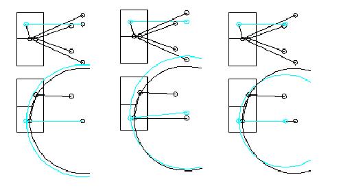
Here are three drawings explaining bump steer. For bump steer to be zero, the arcs made by the tie rod and the spindle must be parallel. For the purpose of this explanation I have made the outer tie rod end the same height as the lower ball joint as it is easier to explain. The first dwg shows the inner pivots of the lower a-arm and the tie rod to be parallel. Even though the tie rod is longer than the a-arm, both arcs are parallel, resulting in zero bump. The second drawing has the tie rod the same length as the first drawing with the inner pivot higher. The arcs are now different resulting in toe out in bump. The third drawing shows the tie rod in the same plane as the lower a-arm (like the first drawing) but shorter, which results in toe in in bump. If you adjust the rack position height per this thread, lower the rack if you are trying to fix toe out in bump, raise it if you have toe in on bump. If you have to choose, toe in on bump is more stable.
Interesting thread... I understand bump steer just fine. Funny timing since I just added some stuff to my cave about it a few days ago.
My main gripe is that people shotgun the suspension and then claim they solved one problem or another. Too often they really have no idea what is fixing what issue. (Others are just trying to sell stuff) I'm glad someone is explaining it because I simply don't want to. Most people talking about fixing bump steer are getting way ahead of themselves.
As noted old and/or defective (Usually defective on a 15-20 year old car...) bushings shocks struts etc have a major effect on any bump steer problems a car may have. All it takes is one weak bushing or strut to make a car dance all over the road. GM put crap for struts on Fiero to start with and way too many people are still running them. 15-20 year old bushings of any type are going to just suck.
This is why I didn't even try to explain most of the Fiero bump steer "problem" in my cave. A hell of allot of people are confusing bump steer with other problems. Technically you can tune or eliminate bump steer in several ways but people with cars as old as ALL Fiero are now need to do the basic suspension run first. Shocks Struts Bushings Alignment (Along with locking down the cradle in poly or metal on the 84-87)
I've seen people site numbers of 1-2 degrees in the stock rear over full travel. Does anyone know what it is say within the middle 4 inches of travel? The middle 2 or 3? Does anyone even know what range of wheel travel is common on this car with good struts and shocks in half way normal operation let alone running an SCCA track? Operational wheel travel is often/usually no where near the limits of travel.
My point asking seemingly obvious questions is that you never hear what the baseline is.
For testing the middle of travel... You don't actually have to tear the car down. You can do it on an alignment rack. Jack the car a bit to test the wheels moving down. Throw weight in the car to compress the suspension to simlulate upward wheel travel. You'll need to carefully load a few hundred pounds of sand bags (or feed) but it should go fairly quick. The better part is you can print the alignment change as you do each step of test. Since we are looking mainly at toe... You don't even need a full rack... A trammel bar and something to let the wheels pivot easily on a flat surface would work. (I'm told a couple scraps of vinyl floor material work. put the scraps top to top with some grease between. You need to test one axle at a time this way...) I don't have any place to do it myself. At least not right now.
That method of testing should be accurate enough to see not only how bad mid range bump steer is but also how well if at all some products claim of correcting it hold up.
------------------ The only thing George Orwell got wrong was the year...
I've seen people site numbers of 1-2 degrees in the stock rear over full travel. Does anyone know what it is say within the middle 4 inches of travel? The middle 2 or 3? Does anyone even know what range of wheel travel is common on this car with good struts and shocks in half way normal operation let alone running an SCCA track? Operational wheel travel is often/usually no where near the limits of travel.
My point asking seemingly obvious questions is that you never hear what the baseline is.
For testing the middle of travel... You don't actually have to tear the car down. You can do it on an alignment rack. Jack the car a bit to test the wheels moving down. Throw weight in the car to compress the suspension to simlulate upward wheel travel. You'll need to carefully load a few hundred pounds of sand bags (or feed) but it should go fairly quick. The better part is you can print the alignment change as you do each step of test. Since we are looking mainly at toe... You don't even need a full rack... A trammel bar and something to let the wheels pivot easily on a flat surface would work. (I'm told a couple scraps of vinyl floor material work. put the scraps top to top with some grease between. You need to test one axle at a time this way...) I don't have any place to do it myself. At least not right now.
Excellent. In EXTREME driving, I would guess that you use no more than about 2” of travel. As I said earlier, the area around normal ride height is critical. Using the full travel is a nice way to see just how close you are in the middle.
Parallel toe strings and “grease pads” can definitely be used for a bump steer gage.
IP: Logged
07:46 AM
Yellow-88 Member
Posts: 454 From: Coventry CT. Registered: Feb 2005
Im not trying to be an ass but would your bump steer correction kit for the pre-88 happen to look something like this? http://www.heldmotorsports.com/bump.htm just being curious. They have an explanation of bumpr steer just below the picture of their product.
No. Mine looks nothing like the Held Motorsports conversion. Mine uses upper and lower control arms and a modified cradle. It matches the geometry of the 88 front end.
IP: Logged
07:52 AM
Yellow-88 Member
Posts: 454 From: Coventry CT. Registered: Feb 2005
As noted old and/or defective (Usually defective on a 15-20 year old car...) bushings shocks struts etc have a major effect on any bump steer problems a car may have. All it takes is one weak bushing or strut to make a car dance all over the road. GM put crap for struts on Fiero to start with and way too many people are still running them. 15-20 year old bushings of any type are going to just suck.
Again Excellent. Bump steer correction is advanced chassis tuning. It is part of chassis design.
Im not trying to be an ass but would your bump steer correction kit for the pre-88 happen to look something like this? http://www.heldmotorsports.com/bump.htm just being curious. They have an explanation of bump steer just below the picture of their product.
personally I think they overcorrected - it can be fixed with parts that can be bolted or welded to the existing knuckle and control arm that does exactly what their kit does.. the thing their kit does not tak einto account is torque stear.. under accelleration you will toe in but much worse under braking you will toe out - only way to stop it with theirs is to use solid swing arm bushings.
IP: Logged
08:13 AM
Yellow-88 Member
Posts: 454 From: Coventry CT. Registered: Feb 2005
My main gripe is that people shotgun the suspension and then claim they solved one problem or another. Too often they really have no idea what is fixing what issue. (Others are just trying to sell stuff) I'm glad someone is explaining it because I simply don't want to. Most people talking about fixing bump steer are getting way ahead of themselves.
Another Excellent.
So often we see a tiny piece of a much bigger issue being used as the “answer” to fix every thing. I opened this thread assuming that I would be addressing those who fully understand the VERY basics.
I ask that you please do not jump headlong into this without first taking the time to learn about the dynamics of the automotive chassis. Once again, I will recommend an excellent text on the subject. It was written in 1976, but the laws of physics don’t ever change. It is, How to make your car handle, by Fred Puhn.
There is no substitute for understanding.
IP: Logged
08:18 AM
Yellow-88 Member
Posts: 454 From: Coventry CT. Registered: Feb 2005
personally I think they overcorrected - it can be fixed with parts that can be bolted or welded to the existing knuckle and control arm that does exactly what their kit does.. the thing their kit does not tak einto account is torque stear.. under accelleration you will toe in but much worse under braking you will toe out - only way to stop it with theirs is to use solid swing arm bushings.
IP: Logged
08:46 AM
Pyrthian Member
Posts: 29569 From: Detroit, MI Registered: Jul 2002
Originally posted by Kohburn: personally I think they overcorrected - it can be fixed with parts that can be bolted or welded to the existing knuckle and control arm that does exactly what their kit does.. the thing their kit does not tak einto account is torque stear.. under accelleration you will toe in but much worse under braking you will toe out - only way to stop it with theirs is to use solid swing arm bushings.
yes, I spent last night thinking about ways to do what they did, but with existing a-arms. what makes theirs so effective is having the "tie rod" on almost the same plane as the a-arm, and almost the same length. this is where bumpsteer comes from, is that the tie rod is on a different plane. it can be done, but after all the work & fab'ing, the $625 for the kit is easily worth it. and I know what you mean about the moving joints in the kit. they look like they will wear quickly and develop slop. they are dry & exposed & doing the job of a greased sealed balljoint. maybe theres a rubber wrap that goes on them, and they just have them off to show off the goods. but, as to deflection from accell & braking, I dont think thats a problem. the tubular a-arm & the high strength metals used look much stiffer than the existing stamped a-arm.
IP: Logged
08:47 AM
Yellow-88 Member
Posts: 454 From: Coventry CT. Registered: Feb 2005
personally I think they overcorrected - it can be fixed with parts that can be bolted or welded to the existing knuckle and control arm that does exactly what their kit does.. the thing their kit does not tak einto account is torque stear.. under accelleration you will toe in but much worse under braking you will toe out - only way to stop it with theirs is to use solid swing arm bushings.
Sorry...forgot my part on that last one.
The “Held” kit requires soft bushings to compensate for the multi axial motion at the outboard end. It is caused by the angle of the bushing centerline being angled relative to the chassis centerline. Correcting that requires parallel inboard bushing centerline.
Just a note to be clear…….. just in case anyone is wondering. I will NOT sell anything, simply for liability reasons. What I’ve learned is to be shared with anyone interested.
yes, I spent last night thinking about ways to do what they did, but with existing a-arms. what makes theirs so effective is having the "tie rod" on almost the same plane as the a-arm, and almost the same length. this is where bumpsteer comes from, is that the tie rod is on a different plane. it can be done, but after all the work & fab'ing, the $625 for the kit is easily worth it. and I know what you mean about the moving joints in the kit. they look like they will wear quickly and develop slop. they are dry & exposed & doing the job of a greased sealed balljoint. maybe theres a rubber wrap that goes on them, and they just have them off to show off the goods. but, as to deflection from accell & braking, I dont think thats a problem. the tubular a-arm & the high strength metals used look much stiffer than the existing stamped a-arm.
its not the arms flexing. i doubt they flex more than a hundredth of an inch stock.. its the bushings, even poly flexes
I could make something equivalent to that for about 60$ in materials - mostly for the rod ends.. but to sell it requires liability insurance same reason i don't want to sell brake caliper adaptors.
The “Held” kit requires soft bushings to compensate for the multi axial motion at the outboard end. It is caused by the angle of the bushing centerline being angled relative to the chassis centerline. Correcting that requires parallel inboard bushing centerline.
you mean colinear right? the axis of the inboard bushings has to line up exactly in order to have solid cylindrical bushings? honestly I'm supprised that they used those instead of the same shperical joints that they used for the outboard pivots..
[This message has been edited by Kohburn (edited 03-10-2005).]
IP: Logged
09:10 AM
PFF
System Bot
Yellow-88 Member
Posts: 454 From: Coventry CT. Registered: Feb 2005
you mean colinear right? the axis of the inboard bushings has to line up exactly in order to have solid cylindrical bushings? honestly I'm supprised that they used those instead of the same shperical joints that they used for the outboard pivots..
No. I mean multi axial. If you look at what happens at the outboard end of the control arm as it moves up and down, you’ll see that it also moves fore and aft, because the inboard end is angled inward. It isn’t much, but Hyde’s poly bushings flex just enough to compensate. Rod ends at both inboard and out board would bind. 3 points would work fine, but that is exactly what we have, and don’t want.
No. I mean multi axial. If you look at what happens at the outboard end of the control arm as it moves up and down, you’ll see that it also moves fore and aft, because the inboard end is angled inward. It isn’t much, but Hyde’s poly bushings flex just enough to compensate. Rod ends at both inboard and out board would bind. 3 points would work fine, but that is exactly what we have, and don’t want.
well with their design yes it would - I find it rather lacking I'll get around to making my custom lower arms with knuckle adaptors soon enough - got a few other projects to finish up first - like the dohc
[This message has been edited by Kohburn (edited 03-10-2005).]
IP: Logged
10:10 AM
opm2000 Member
Posts: 1347 From: Versailles, Ky USA Heart of the Bluegrass Registered: Dec 2000
I allways liked this writeup. The diagram certianly makes it clear why our Fiero rearends experience bumpsteer. Your two control arm setup might work well. Why aren't you sharing pics with us?
A. Definition
Bump Steer is when your wheels steer themselves without input from the steering wheel. The undesirable steering is caused by bumps in the track interacting with improper length or angle of your suspension and steering linkages.
Most car builders design their cars so that the effects of bump steer are minimal. However, you must still take care to bolt on your suspension carefully so as not to create unwanted bump steer. Make sure that you are always using the correct components for a particular car. Bump steer must be designed into the car and cannot be adjusted out if improper parts are used or if pivot points are moved without considering bump steer design principles.
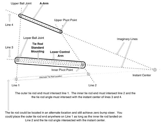
In order to accomplish zero bump the tie rod must fall between an imaginary line that runs from the upper ball joint through the lower ball joint and an imaginary line that runs through the upper a-arm pivot and the lower control arm pivot. In addition, the centerline of the tie rod must intersect with the instant center created by the upper a-arm and the lower control arm (See diagram below).
The instant center is an imaginary point that is created by drawing a line from the upper a-arm ball joint through the a-arm pivot where it is intersected by an imaginary line that extends from the lower ball joint through the inner control arm pivot. Where the two imaginary lines intersect is the instant center.
Sounds complicated? Really it is very simple. To achieve zero bump the front end must be designed correctly. The tie rod must travel on the same arc as the suspension when the car goes through travel. Simply matching lengths and arcs to prevent any unwanted steering of the front tires.
To exaggerate, if the tie rod were only 10" long and the suspension were 20" long then when the suspension traveled the tie rod angle would shorten much quicker than the suspension arc. In this scenario the tie rod would shorten much quicker through travel than the suspension and the car would toe in drastically over bumps. The shorter arc of the tie rod would pull on the spindle and toe it in through travel.
Bump Simplified - When designing a car, if the centerline of the outer tie rod lines up with the centerline of the lower ball joint, and the inter tie rod lines up with the lower pivot point then the length and angle of the tie rod and suspension will be the same resulting in zero bump. Most car builders design their cars in this fashion.
B. Preparing the Car for Bump Steer Measurement
Your front suspension must be complete and set for racetrack conditions before you can measure the bump steer. All components must be tight and in proper position and you will need a quality bump steer gauge.
Set the car at ride height. Use the proper size tires and air pressures. Caster must be set. Camber must be set. Toe in must be set. Tie rod lengths must be set. Steering should be centered (tie rod ends centered on inner pivot points lower ball joints). Steering must be locked down. Measure from the ground to the lower ball joint or other reliable reference point. Write the number down. Remove springs and disconnect the sway bar. Return the suspension to the proper height by using your reference number to the ground. Obtain a supply of bump steer shims. Bolt on the bump steer plate to the hub. Level the plate and note where the dial indicator is on the bump steer plate so that you can quickly return to the correct ride height. Jack the suspension through 2"-3" of both compression and rebound travel and write down your results. Shim as needed. C. Making Bump Steer Corrections
Now that you have measured your bump steer you will need to adjust, shim or relocate the suspension components to get the exact reading that you desire. Below are some tips that will quickly guide you through the corrective process for cars with front steer style suspension.
Symptom Cure Symptom 1. Toes out in compression and in on rebound all in one direction. Cure 1. Decrease shim on outer tie rod or lower the inner tie rod.
Symptom 2. Toes in on compression and out in rebound all in one direction. Cure 2. More shim at outer tie rod or raise the inner tie rod.
Symptom 3. Always toes in both compression and rebound. Cure 3. Lengthen the tie rod as it is too short.
Symptom 4. Always toes out on compression and rebound. Cure 4. Shorten tie rod as it is too long.
Symptom 5. Toes out on compression, then in on rebound and then starts back towards out with more rebound travel. Cure 5. Less shim at outer tie rod and shorten tie rod.
Symptom 6. Toes in on compression, then moves out on rebound and then starts back towards in with more rebound travel. Cure 6. More shim at outer tie rod and lengthen tie rod.
D. Using the Bump Steer Gauge
Selecting a good bump steer gauge makes the process easier. I like the bump steer gauges that utilize only one dial indicator. One dial indicator bump gauges do the math for you and you avoid having to watch two dial indicators move at the same time. Sometimes when the bump is way out of adjustment it takes two people to watch both of the indicators. The one indicator design is much easier to use.
When you set up your bump steer gauge with the car at the proper height set the dial indicator at the center of the bump steer plate and be sure that the indicator is set in the middle of its range. You want to avoid running out of indicator travel.
Once the indicator is set simply jack the suspension through 2"-3" of compression. Stop at each inch and record your reading. Repeat the process through rebound and record those numbers at each 1-inch interval.
If the front of the bump steer plate is moving towards the engine then you have a bump in condition. If the front of the plate moves away from the engine then you have bump out. The dial indicator will see small amounts so watch it carefully and note your results.
E. How Much Bump Steer ?
Ideally you should run as little bump steer as possible. Most of the tracks we see today are old and bumpy. Bump steer on these rough surfaces causes the car to be unpredictable.
Some bump out can make the car more stable on corner entry. Bump in is almost always undesirable.
Some people use small amounts of bump out to create entry stability and an Ackerman type effect in the center of the turn where as the bump setting causes the LF to turn a bit farther than the RF as the RF compresses and the LF extends.
My recommendation is to run .005 to .015 thousands of bump out but never allow the tires to bump in.
If you want Ackerman in the center of the turn then add Ackerman while maintaining proper bump. If you use bump to obtain some Ackerman effect the car will be unsettled as it goes over each bump, which will break the contact patch from the racing surface.
If the design of your car does not allow for such precise bump adjustments then more bump out is better than any bump in. However, strive to get the best bump numbers even it if means replacing parts. Excessive bump over .050 can slow your car down.
F. Diagram
>>above from racerpartswholesale.com<<
David Breeze
------------------ Pantera Rebody Kits
IP: Logged
10:17 AM
Pyrthian Member
Posts: 29569 From: Detroit, MI Registered: Jul 2002
yes, that whole arm that holds the knuckle has to do the job of a balljoint. for the most part it will just be rolling on its long axis, as the car goes over bumbs. but, for the toe in/out adjustment, it also has to have flex in that direction. either way, I do beleive this setup is MUCH better than the existing setup, but I do not beleive it can last 20 years, like the eixtsing one has. the dry exposed joints will wear & develop slop quickly. I suppose you can grease them, then shrink wrap them, or maybe get rubber boots. I would hope they really are covered, and just exposed in the pics to show how it works.
IP: Logged
10:23 AM
Yellow-88 Member
Posts: 454 From: Coventry CT. Registered: Feb 2005
I allways liked this writeup. The diagram certianly makes it clear why our Fiero rearends experience bumpsteer. Your two control arm setup might work well. Why aren't you sharing pics with us?
I dont own a digital camera. Yeah really..!! I'm an analog guy in a digital world.
IP: Logged
11:27 AM
Yellow-88 Member
Posts: 454 From: Coventry CT. Registered: Feb 2005
Bump Steer is when ...... In order to accomplish zero bump the tie rod must fall between an imaginary line that runs from the upper ball joint through the lower ball joint and an imaginary line that runs through the upper a-arm pivot and the lower control arm pivot. In addition, the centerline of the tie rod must intersect with the instant center created by the upper a-arm and the lower control arm ........The instant center is an imaginary point that is created by drawing a line from the upper a-arm ball joint through the a-arm pivot where it is intersected by an imaginary line that extends from the lower ball joint through the inner control arm pivot. Where the two imaginary lines intersect is the instant center.
Sounds complicated?
Selecting a good bump steer gauge makes the process easier. I like the bump steer gauges that utilize only one dial indicator. One dial indicator bump gauges do the math for you and you avoid having to watch two dial indicators move at the same time. Sometimes when the bump is way out of adjustment it takes two people to watch both of the indicators. The one indicator design is much easier to use.
Sounds complicated?
David Breeze
Please forgive my sence of humor David. This is NOT AT ALL a blast at your very complete post. I just could'nt help taking some of it out of context for the shear fun of it.
Thankyou.
IP: Logged
11:45 AM
Yellow-88 Member
Posts: 454 From: Coventry CT. Registered: Feb 2005
yes, that whole arm that holds the knuckle has to do the job of a balljoint. for the most part it will just be rolling on its long axis, as the car goes over bumbs. but, for the toe in/out adjustment, it also has to have flex in that direction. either way, I do beleive this setup is MUCH better than the existing setup, but I do not beleive it can last 20 years, like the eixtsing one has. the dry exposed joints will wear & develop slop quickly. I suppose you can grease them, then shrink wrap them, or maybe get rubber boots. I would hope they really are covered, and just exposed in the pics to show how it works.
The Held Motor sports design is a crude patch for a really lousy design. It will work a bit better than the OEM design, but I agree with you about longevity.
So lets dream. Once you remove the ball joint you’re faced with inboard end of the control arm’s need to be parallel to the chassis centerline. In dealing with that, you’ve re-done some of the cradle. At that point the hub carrier starts to look wrong. Something aluminum would be nice. Oh look.....this one takes big brakes! Once you’re that far, why not lose the Chapman strut geometry, and add an upper control arm to get some proper camber change. How about anti-squat geometry, and adjustable roll bar while you’re at it.
I haven’t yet bolted it onto a car, but on the bench the geometry checks out, and it looks like the sort of thing you’d put in a mid-engine sports car. Now where do we find one of those......Oh look there's a yellow one outside..!!
I try to avoid discussing the Held system but since it's up...
Whether or not is fixes anything is only one of a couple things to look at. The use of Hiem joints in a street car is not a good thing. Besides most of them wearing quickly due to contamination and lack of lubrication, this system loads them in a way they aren't made for. (Lined joints could actually fail sooner because of how they load on this setup.)
Hiem joints are made to be load bearing only in the plane of the ring. Not thru the ring. You can dislocate a Hiem joint due to wear and stress in fairly short order doing that. It is also posible to fracture the ring or snap it off the stud like that.
At first glance you'd think they are always loading in ring plane as it were and I would expect the front ones are. The rear one is the problem as it takes a huge off plane load in braking. Most of the force of braking is pushing into that joint. Under acceleration you are loading it in the other direction along the ball's thru bolt.
That I can see there is nothing to prevent a failure of that rear hiem joint from resulting in sudden and likely catastrophic failure of the rear suspension.
There is no way to really predict the reliability of that rear ring without some very expensive testing. Depending on the car and how it's driven it could last years or fail in no time.
Many things used in racing don't translate well to the street. Polyurethane and Hiem joints for control arms are a couple of them. Both create as many problems as they might solve.
I was right with you till the poly.. how does using a stiffer flexible material cause problems other than increased vibration/road feel?
I actually think their design would benefit more from lubricated roller bearings inplace of the poly inboard bushings - and replace the outboard heim joints with poly bushings that include poly thrust washers.. this would allow enough flex to avoid binding, prevent the worry of that thrust loading the spherical joint, and stiffen up the inboard pivots where the loads are highest during accelleration and braking to prevent toe change from torque stear.
the setup I designed up can use either roller bearins, self lubricating bronze bearings, or greasable plain bearings with no worry of binding.. my inclination is to use self lubricating ones and use dirt seals.
[This message has been edited by Kohburn (edited 03-11-2005).]
IP: Logged
07:31 AM
Yellow-88 Member
Posts: 454 From: Coventry CT. Registered: Feb 2005
There is no way to really predict the reliability of that rear ring without some very expensive testing. Depending on the car and how it's driven it could last years or fail in no time.
Many things used in racing don't translate well to the street. Polyurethane and Hiem joints for control arms are a couple of them. Both create as many problems as they might solve.
t is very easy to see ourselves as great engineers. For ourselves, we can build seemingly elegant designs that appear to function beautifully. But in doing that, we will not have to face the vast public use of them. OEM designs are meant to be above all, dependable under amazing abuse.
Let me offer this to all of us who wish to test our design on the real road. Take time to do some research, and not just here on this form. Be aware that a salesman is SELLING a product. Be as sure as you can about the loads and forces acting on your design. Oversize your parts….just in case.
IP: Logged
08:05 AM
PFF
System Bot
Will Member
Posts: 14226 From: Where you least expect me Registered: Jun 2000
There have been elements of the "multi-axial" motion in the rear that have been left out.
The inner control arm pivot axis is lower and wider in the front than in the rear. It's lower because this was originally a front suspension that had anti-dive geometry. This translates to PRO-squat as a rear suspension. I don't know why the forward pivots are further out than the rears... maybe whoever designed it was smoking something.
There's another axis to consider, and that's the kingpin. The suspension I have in mind involves a rigid pivot axis inboard and a rigid pivot axis outboard, which must be parallel to each other. In order to do this without binding, the strut must be perpendicular to the pivot axes in the side view.
It's the interaction between the inner pivot axis and the upper pivot point of the strut that necessitates the Held kit being designed with inner and outer axes that are not rigid relative to each other. The stock hub carrier really shows itself poorly adapted to solving this problem.
I think that something closer to the '88 rear hub carrier, with its strut mounting boss offset relative to the axle centerline, would be a better place to start than a FWD hub carrier that must be designed with the strut mount in plane with the axle.
I think a custom H-arm, rear inner pivot relocation bracket, and a fabbed aluminum hub carrier based on the '88 rear would be a great place to start...
Once the bump steer and pro-squat are corrected, I think that the benefits of going all the way to SLA setup will be minimal.
IP: Logged
09:09 AM
Yellow-88 Member
Posts: 454 From: Coventry CT. Registered: Feb 2005
There's another axis to consider, and that's the kingpin. The suspension I have in mind involves a rigid pivot axis inboard and a rigid pivot axis outboard, which must be parallel to each other. In order to do this without binding, the strut must be perpendicular to the pivot axes in the side view.
It's the interaction between the inner pivot axis and the upper pivot point of the strut that necessitates the Held kit being designed with inner and outer axes that are not rigid relative to each other. The stock hub carrier really shows itself poorly adapted to solving this problem.
I think that something closer to the '88 rear hub carrier, with its strut mounting boss offset relative to the axle centerline, would be a better place to start than a FWD hub carrier that must be designed with the strut mount in plane with the axle. I think a custom H-arm, rear inner pivot relocation bracket, and a fabbed aluminum hub carrier based on the '88 rear would be a great place to start...
.
Yes. A very logical place to start an IRS rear design is as you describe. In doing so, you can even go so far as to eliminate a need for toe adjustment, as is done in the Lotus Esprite. By including an upper control arm, you’re free to explore whatever camber, and caster geometry you choose. A rear hub carrier is relatively easy to fabricate, compared to a front.
In my design, I used a pre-88 cradle, and relocated the inboard a-arm mounts. The inboard end of the new control arm pivots on solid greasable bushings, while the out board end uses neoprene sealed rod ends. I provided limited toe adjustment because I needed a bit of fudge factor in my fabrication. My first hub carrier was a modified 88, but the new one will be an aluminum fabrication.
IP: Logged
09:59 AM
Will Member
Posts: 14226 From: Where you least expect me Registered: Jun 2000
I think it definitely needs toe and camber adjustments... The ideal toe requirements of a non-bump steering Fiero are likely different than those of a bump steering Fiero.
Originally posted by Kohburn: I was right with you till the poly.. how does using a stiffer flexible material cause problems other than increased vibration/road feel?
Polyurethane, aside from its well documented squeaking issues actually wears considerably. Polyurethane operates as a bearing in the control arms. Dry bearings wear. Fast. If you are squeaking you are wearing but it isn't always that obvious as dry ploy doesn't always squalk, especially when it is already worn. Polyurethane is a bloody poor bearing material to start with. Adding graphite and other compounds to the material don't really change that much.
There are good uses for polyurethane but control arms on street driven vehicles isn't one of them.
As for various other bearing types... These can actually make problems even worse than the Hiem joint issue I mentioned above. A street suspension MUST have a certain amount of give in the mess or you will break/bend things very easily. OE rubber bushings prevent a hell of allot of damage to the vehicle. A good fresh set of OE control arm bushings will give virtually identical perfromance to any poly set and will last 50-100,000 miles with ease.
I'll give you an example of a car that came factory with a solid bearing assembly in a control arm... The Ford Maverick. These had a pair of greased steel bearing cups on a steel pivot bar holding the UCA. This was great in theory. On the road it didn't take long for the O ring to die and crud to start getting into the bearing. I've seen the bearings hogged out to 1/4 inch or more of play. Now I'm sure someone will chime in and say this was the owner's fault for not greasing them... Problem is Ford plugged them and there was no room to install fittings or even get at them unless you literaly cut holes in the spring tower. A little outside normal maintenance...
Along a similar vein... Many people say you should mount a rack solid. Doing this will accerate wear on the rack and could even cause the thing to grenade.
Yes, some racing calls for x or y change/product. That doesn't mean it will work or be even remotely safe on the street. It works both ways... There are allot of things on the street that aren't remotely safe in many race classes.
IP: Logged
07:00 PM
Mar 13th, 2005
Will Member
Posts: 14226 From: Where you least expect me Registered: Jun 2000
I agree on polyurethane. I advocate the use of UHMW and XL UHMW for suspension bushings... more slippery with less bind than polyurethane, but very long wearing. It just has to be machined rather than formed.
The lubricity of the material used for the bearing isn't the only problem. As I noted any solid sort of bearing can be a bad thing for a street driven car. The stuff you mention and other things are better bearing materials but they have no "give" in them. UHMW Delrin and other hard plastics may as well be steel to the car.
I know the rubber bushings seem like a bad thing to many people but there isn't really anything better when it comes to making a car last. This is one big reason why every car maker on the planet uses the stuff. Without the compliance a rubber bushing brings, you can and very often will chew thru ball joints and other things at an alarming rate. It isn't just about ride quality for the ocupants but longevity of the vehicle itself.
Allot of people look at the rubber bushing as being nothing more than a pivot. In reality they are also shock absorbers and springs in one. They take up the small but constant string impacts the suspension sees in normal driving. I'm not even talking about potholes. The bushings absorb things like joints and cracks that cause hardly any virtical wheel travel.
If you are building a full race car and need every fraction of a second, then some of the more solid control arm bearing/bushing materials could be very good for you. (8shark has done allot of work along just this line.) My biggest concern is that people use materials like this on the street and they don't understand the tradeoffs they are making in longevity and often the safety of a vehicle.
IP: Logged
07:30 PM
Will Member
Posts: 14226 From: Where you least expect me Registered: Jun 2000
I think the kind of person who can replace suspension bushings and is discerning enough to pick UHMW over poly will keep track of his ball joints.
For me, the improvement in handling with hard bushings is more than worth it.
Besides, I'm going to be ditching the rear ball joints soon...
Indeed. Those of us making the kind of changes being discussed here are very aware of what we’re doing. I believe that one of our obligations is to be sure we don’t inadvertently advocate such practice to those who don’t yet fully understand the seriousness of it.
IP: Logged
10:03 AM
Pyrthian Member
Posts: 29569 From: Detroit, MI Registered: Jul 2002
well, not all of us - lol. I thought the poly a-arm bushings & cradle bushings would last a good long time. the suspension is supposed to take the vibration & shocks. well, I guess the cradle bushings will last forever - no real movement there. anyways, this is a bumpsteer correction thread. and it seems, the consensus on the Held kit is - it works - works well, but for a limited time only. It does feed ideas on how to tie the tie rod to the a-arm, intead of the cradle tho. how about a ball joint that just plain old doesnt rotate, except thru adjustment?


 - only way to stop it with theirs is to use solid swing arm bushings.