As some of you know I am working on a 4.9 swap and now I am trying to finish the wiring. I finished labeling the C500 and some of the C203 to be able to connect them to the 4.9 harness but I have some questions and I am hoping that some of you will help me out.
1- There is a brown cable coming from the big plug that connects the eng harness to the harness coming from the firewall. It is on M7 location on the big plug. What is that cable for and where do I connnect it ? I looked it up in the wiring diagram and that cable was not there.
2- The plug from the alt was cut off from the 4.9 harness that came with the eng. I got another alt plug from a different, earlier model 4.9. How do I wire the alt plug to connect it to the 1992 4.9 harness ? I think there is 3 or 4 little wires coming out of the plug.
3-Where is the AIT ( air intake temp) sensor cables on the 4.9 harness ? I don't think I have them in my harness, could I use the 2.8 Fiero harness and sensor ? I am talking about the sensor that is on the round air induction canister.
4- How do I wire the A/C and Fuel pump relays in the 4.9 harness ? Can I use the ones from the Fiero harness since I don't have any relays on the 4.9 harness?
5- I have a loose black cable that "merges" to another black cable comming from sensor that goes to the rear head on top left side, just below the valve cover next to trunk ( with 4.9 mounted on Fiero) The other black cable ( that is connected to it) goes to the A/C compressor and has a "loop" with a small resistor inside some type of heat shrink. I think that black cable is supposed to be grounded somewhere but I am not sure. Do any of you know where that cable should be connected to ?
Thank you in advance for any help, I will be greattly appreciate it.
ps on a side note, I am really surprise that some of you have not notice, some little different things in the background of the pictures, on the tread "My Home made 4.9 swap", since I know some of you guys have really good eyes....
[This message has been edited by 85LAMB (edited 12-31-2004).]
IP: Logged
01:52 PM
PFF
System Bot
Kento Member
Posts: 4218 From: Beautifull Winston Salem NC Registered: Jun 2003
Hey if you are able, swing by this weekend, going to be working on mine and want you to see what is going on
------------------ 4.9 Caddy in Garage! Car in Driveway! ACK! **************************************** http://home.cfl.rr.com/fierose Central Florida Fieros http://www.centralfloridafieros.org Proud Member and founder of the DOWN SOUTH SUNNY WINTER PICK ON SNOW PEOPLE COALITION!
[This message has been edited by Kento (edited 12-28-2004).]
Fuel relay - just use the Fiero one, connect the output from the Caddy ECM to the relay as was the Fiero ECM (I would assume A/C is very similar, I have not done an A/C car so I will leave it alone).
Mickey Thank you very much for your reply + for you.
I am not that great at wiring and don't have access to a more detailed wiring diagram for the Fiero, other than my Chiltons and Haines manuals. Do any of you have links to somewhere I will be able to download some ?
I really could use more input on this...... I am hoping more of you guys will help me out.
IP: Logged
04:54 PM
htexans1 Member
Posts: 9110 From: Clear Lake City/Houston TX Registered: Sep 2001
From fiero addiction .com's site a 4.9 wiring page WITH Schematics for both the caddy and Fiero.... http://fp.enter.net/~rockcrawl/fierowiring.html It just may help. give it a try. S.Williams
------------------ 1988 Fiero Formula T-tops CJB 143 of 1252 "factory T-top cars"
IP: Logged
09:53 PM
Dec 30th, 2004
jeffndebrus Member
Posts: 2772 From: Jacksonville, Fl- usa Registered: Aug 2001
Hey Lincoln, Merry Christmas and Happy New Year! I really wish I could help you. There are plenty of homemade 4.9'ers out there. As you know I puked up the $700 for Ed Park's harness so I don't know a thing about the integrated wiring swap but I wish you all the best!
------------------ Proud Member of the DOWN SOUTH SUNNY WINTER drive your Fiero Naked Coalition. 85 4.9SE 4T60E Parks harness/ Rockcrawl chip-- No I do not want to race!
htexans1 Thank you for the link, + for being helpfull , I alreally have those diagrams but I am still stuck. I have been doing a lot of reasearch on this but I still need some help.
Jeff Merry Chistmas and Happy New Years to you as well I know I am close to finishing the harness I just need a litle help. I hope you take care of the alt.
IP: Logged
05:41 PM
Kento Member
Posts: 4218 From: Beautifull Winston Salem NC Registered: Jun 2003
htexans1 Thank you for the link, + for being helpfull , I alreally have those diagrams but I am still stuck. I have been doing a lot of reasearch on this but I still need some help.
Jeff Merry Chistmas and Happy New Years to you as well I know I am close to finishing the harness I just need a litle help. I hope you take care of the alt.
Hey, Print them all out and bring them over this weekend and I will see what I can figure out. Had 4 year Electro-Mech drafting. I hate wiring but I know how to read them.
IP: Logged
05:49 PM
Mickey_Moose Member
Posts: 7498 From: Edmonton, AB, Canada Registered: May 2001
The only really wiring diagrams you need are what you can download at Rockcrawls site.
The best thing I can suggest is to go back to your original Fiero motor harness - any wiring that connected from the motor to C500 and C203 plugs needs to be connected to a similar spot on the 4.9 (ie. tach wire from C500 goes to tach output on 4.9, etc). What year is your Fiero? A pinout for your specific year of Fiero for the C500 is helpful.
AIT ( air intake temp) sensor cables on the 4.9 - don't worry about it, the 4.9 has all the sensors it needs.
Grounds - originally some where connected to one of the 'studs' the holds the transmission to the motor.
Kento I will probably will take you up on the offer, I will try to stop by Sat or Sunday, I will call you before I go to your place.
Tim My Fiero is an 85 GT auto. I Found some more diagrams and have spend a lot of time going over them today, I made some progress, hopefully with a friend's and Kento's help I might be able to get it done. Thank you for your help
IP: Logged
12:41 AM
PFF
System Bot
Mickey_Moose Member
Posts: 7498 From: Edmonton, AB, Canada Registered: May 2001
Guys I have a couple of more questions: thank you in advance for your help
On the 7 pin connector on transmission where do I connect letter D ? It is supposed to be fused power, it's pink /blk on the wire coming from trans and I think is purple on the other side of the plug.
On the C500 connector on Rockcrawl's site it states that C1 and E1 are both for Reverse: a) Do I connect both (C1 and E1) to letter F on the 7 pin Connector for the transmission ? or b) Do I connect C1 from C500 to D on 7 pin connector on trans and E1 from C500 to F on 7 pin ? c) neither one of the above, NOTE: if c is correct please tell me what is the correct way to do it.
IP: Logged
10:19 PM
Jan 4th, 2005
Mickey_Moose Member
Posts: 7498 From: Edmonton, AB, Canada Registered: May 2001
C500 C1 and E1 when shorted together cause the backup lights to come on (going from memory here), on a manual transmission car they connect to a physical switch, so I imagine they would connect in a similar manner to the auto, but with pins I can not say.
Sorry I can't help you out with this one, I have only done standard installs and have no notes for the auto.
Alright, I have done my studying and the results are in........ Go with answer B. C1 is your fused power so it goes in pin D, E1 goes with pin F and you should be good to go. I will say that I am looking on a service manual from a 91 Deville and these are year specific, but from what you had come up with, it sounds like the same thing only maybe the color of wires have changed. Same with the fiero. It's an 87 specific, but looks like what you're looking at. Hope this helps. Let me know. hope you get rolling soon. I'm not getting mine started till this summer. Darren
What other questions are you still needing answers to? Of the questions at the top of this post, which ones do you still not have figured out? I will try to give you a hand, but don't want to waste time on ones that are already answered. bump for this thread as well. Darren
Originally posted by Darren's 87 coupe: What other questions are you still needing answers to? Of the questions at the top of this post, which ones do you still not have figured out? Darren
Darren, Thank you very much for helping me out, you get a + from me. The questions I have not figured out are 1, 3 and 5, Any help would be greatly apreciate it. Lincoln
IP: Logged
07:07 PM
Jan 9th, 2005
PBJ Member
Posts: 4167 From: London, On., Canada Registered: Jan 2001
3: IAT, Intake air temp sensor on the 4.9 is mounted on the top of the intake near the frt of the engine. So in the harness it will be very close to the alternator connector and number 2 fuel injector plug.
5: Since it is a black wire I would say it is likely a ground. Now if the other wire at the a/c compressor connector is Dark Green then it is a ground and should be grounded on the engine. The small resistor type thing is actually a diode used by the a/c compressor. The sensor on the head is used in the caddy for the over heat light.
btw, nice bike! We had a 2000 Suzuki SV650 Pretty quick and good for insurance cost.
Hope this helps.
Pete
------------------
[This message has been edited by PBJ (edited 01-09-2005).]
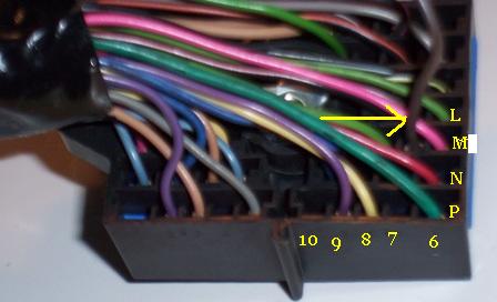
Pete Thank you for helping me out , you made my day I was not sure about the IAT so I am glad you told me. Also thank you for verifying the black wire, I will ground it to the head. Here is a picture of the connector I was talking about, the cable is located on M7, the one to the left of the pink wire on the photo below. It is not connected to anything on the eng side or the PCM side. The plug is the one on the PCM side, that has the 3 plugs that connect directly to the PCM.
Can you please verify, that the connections below are correct: C1 from C500 to D on 7 pin connector on trans and E1 from C500 to F on 7 pin connector on trans side (on a 85GT and 92 Deville ). I am the type that would rather double check something to make sure is rigtht than have to go back and try to fix something later on. Thank you for the compliment on the bike, what surprises me is that no body has notice anything about the car where the eng is in. Thanks again, I wish I could give you another plus Lincoln
IP: Logged
06:01 PM
PBJ Member
Posts: 4167 From: London, On., Canada Registered: Jan 2001
The picture should be very helpful. I do not have a Caddy service manual at all. At my work we also do not keep caddy dealers since we sell only Pontiacs and Buick. I use only Rockcrawls web site. www.fieroaddiction.com Someone with a manual should be able to pick off what wire that is shortly. Meaning when I wire up a 4.9 I completely remove this plug pictured and wire from the sensors directly to the ecm. As for the reverse lights, I use a Volt meter and pin it out by hand on the car, it is always the last thing I do and have never documented in my notes.