I have had many inquiries on my LS1 swap that it has been hard keeping up. everyone is going to start to think I am rude... Not true LOL. So I am going to start a thread here going through all the individual parts in detail.
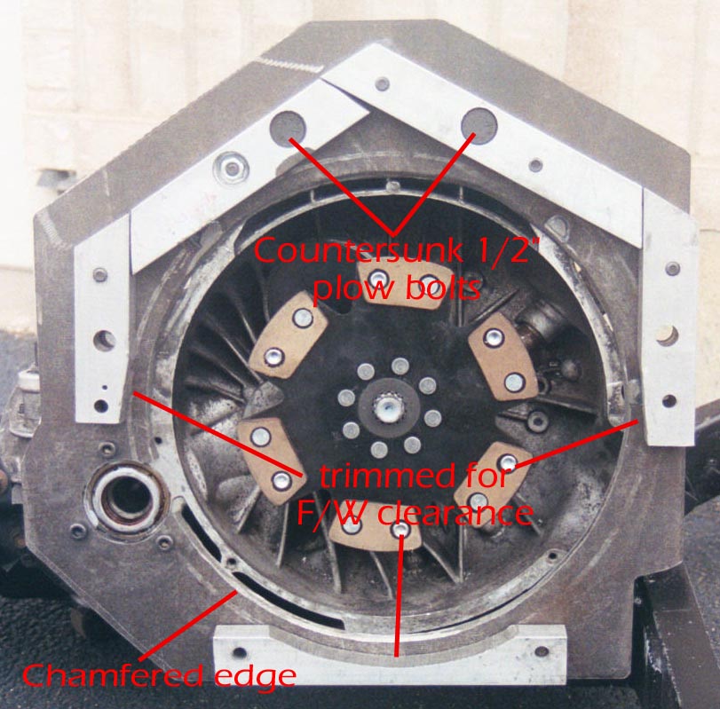
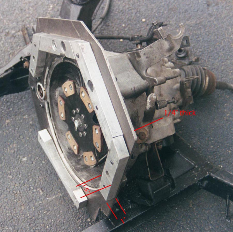
I will start with the adapter plate. My adapter plate is multi part. It consist of 1" thick 6061-T6511 solid flat stock by 1 1/4" wide (alf1x1.25) I required about three feet of this. The other part of the plate is a 19"x19" � hot rolled sheet steel. I then had the sheet CNC drilled at a local machine shop with my supplied CAD drawings. I cut the circular hole and outside shape myself. You may note that the plate encircles both the entire flywheel and the rear axle. This is done for strength. It allows the plate to catch the bottom two mounting holes on the LS1 block and the three bolts on the differential housing. I did this because there is one bolt that can not be used on the trans( it is the one that come from the block side near the back CV joint.) Ps. All my steel was purchased from Metal Express. www MetalMart.com fortunately for me there is one close by, for it is allot cheaper if you can avoid the shipping charges. Here are the pics
[This message has been edited by LS1swap (edited 10-04-2002).]
[This message has been edited by LS1swap (edited 10-04-2002).]
IP: Logged
11:29 PM
LS1swap Member
Posts: 1181 From: McHenry,IL.USA Registered: Jan 2001
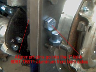
There are eight 10 mm bolts that go into the LS1 block all are used. There are six (only five are used) 1/2" grade 8 , and three 8 mm grade 10.9 bolts used to hold the trans to the adapter plate, and two 5/8 " alignment pins. All holes were drilled by the CNC shop off the CAD drawings I supplied them with. The 10 mm ones were drilled to 25/64 (just under 10 mm) this makes for an interference fit of the bolts for the adapter plate. The half inch ones were drilled to 27/64 the size required for a 1/2" tap. Three of the half inch holes end up being studs welded flush with the block side of the plate( look at pic) the other are through bolted. The chevy powerbook didn't have the three 8 mm bolts around the differential so after all the other bolts were in place I found there location as follows. I threaded in three cone point 8 mm set screws so they all protrude about 1/4" then I slid the plate up to them ( note all the other bolts are in at this time to hold it in line ) then I hit the plate just hard enough to make three dimples in it. Then the plate can be removed center punched deeper and drilled. The points on the trans alignment pins were cut off so I could have two pins come in from the adapter plate side . This assures alignment and prevents the torsion rotation between the block and trans.
IP: Logged
11:33 PM
LS1swap Member
Posts: 1181 From: McHenry,IL.USA Registered: Jan 2001
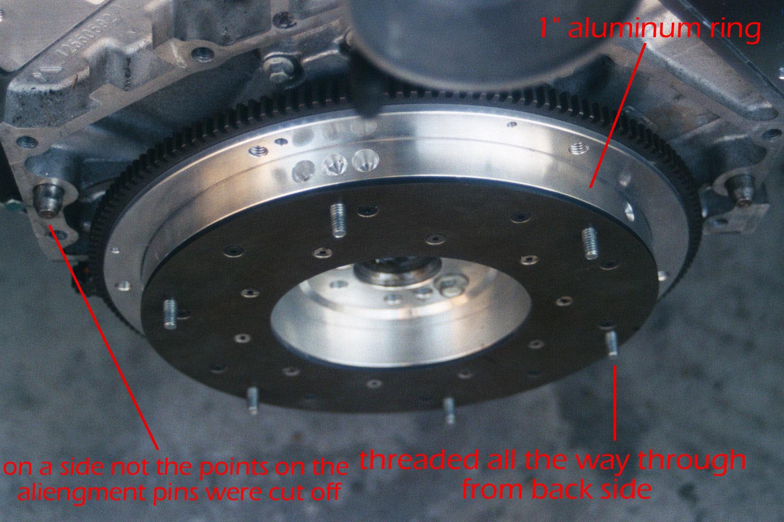
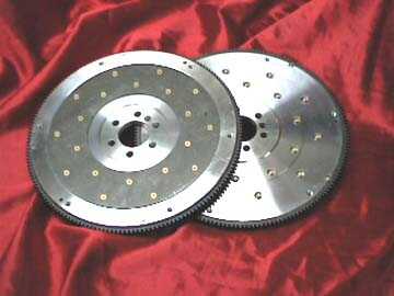
The flywheel I started out with a 168 tooth aluminum F/W for a LS1 from fasttoys.com it is made by fidanza PN: C5-1260( fasttoys part numberFIDAFLS1) $359. This F/W has a removable steel friction surface held on by twenty 3/16" grade 8 tapered socket head bolts. this has to be removed. In the recess the friction plate was in I added a 1" thick aluminum ring the exact same size as the steel friction surface that was removed. Then the friction surface is put back on top ( this achieves the correct back spacing into the trans) and the aluminum ring is drilled for the twenty grade 8 tapered head bolts. I had to order new ones of the longer length through fastenal.com (once again there is one in my home town) the ones I got were the correct taper but had a head that stuck up from the friction surface (not good) so I had to lightly grind ( about 1/32) off the center 10 bolts ( note in the pic they are shinny) after the ring and friction surface are mounted it needs to be taken back to the machine shop and have the pressure plate mounted. I had the entire f/w drilled and tapped with the six 5/16-13 bolts. ( I wanted grade 8 but could only find grade 5 in full thread). these bolts are through threaded from the back side. After all is said and done the f/w needs to be balanced. Take the F/W and presure plate with you. Have them first balance the F/W then have them add the pressure plate and balance it again. but they need to do this by adding weight to the pressure plate and not changing the f/w balance( note two small studs in pic). They should know to index the two but I took no chances and indexed them with a sharpy marker and made a note of it to them. I then installed a 86-88 v6 5spd kevlar clutch kit 54003R $272.00 from the Fiero store it holds good now but it is too soon to comment on its longevity.
IP: Logged
11:39 PM
LS1swap Member
Posts: 1181 From: McHenry,IL.USA Registered: Jan 2001
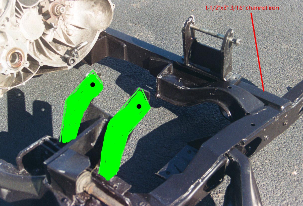
The cradle needs to be modified for the LS1 the pan is just too wide to fit. I placed a 1-1/2"x3" 3/16" wall channel iron against the forward cross member on the cradle. there are two ears that sit atop the cradle and it was bolted to the cross member for welding. At that point I had it welded, and only then did I cut out the portion of the cradle that gave me interference. This assured that the cradle remained the correct size, and shape. This new front cross member also serves as a support for the forward engine mount. On the back side of the cradle I welded on a support for the rear engine mount. On a side note I tried to approximate what the final design of the rear mount looks like ( I am no artist LOL)
IP: Logged
11:45 PM
LS1swap Member
Posts: 1181 From: McHenry,IL.USA Registered: Jan 2001
Front mount I used the stock clamshell motor mounts that came with my engine. Is was important to me to have the rubber mounts for vibration dampening. The clamshell mounts need to have a little stem cut off of them so that the supports I fabricated can hold it secure. The front engine mount is pretty simple just straight up with a gusset to hold the two uprights in line. It rests on the channel iron that was added to the cradle earlier. The only oddity is that the nut for the bolt that goes through the clam shell needs to be countersunk into the mount for starter clearance. You can see a picture of it in the post above.
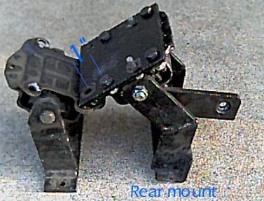
I have a better view of the engine mounts (pic below) it shows the actual shape of the rear mount. With the small adapting plate that slides the rubber clam shell mount up the block about an inch. It also shows the front mount, but it is the same as it is in all the other pictures
[This message has been edited by LS1swap (edited 01-20-2003).]
IP: Logged
11:47 PM
LS1swap Member
Posts: 1181 From: McHenry,IL.USA Registered: Jan 2001
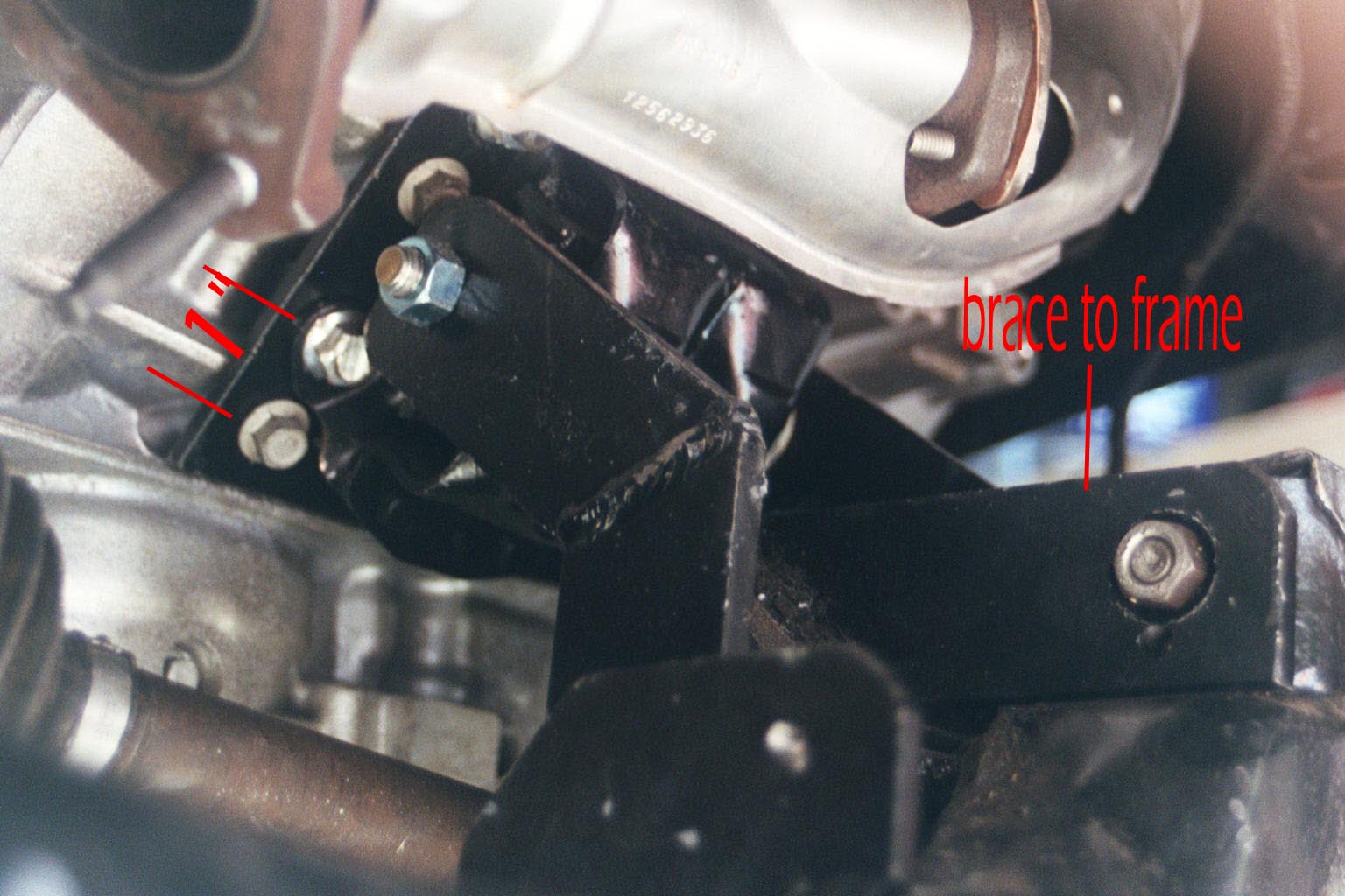
Rear mount The rear mount is a little more tricky. The clamshell type mount on the block should be moved up about an inch for better clearance of the axle. This was accomplished by making a plate that both the mount and block attached to with the hole offset about 1". I then made a cardboard template and then duplicated it in 2"x 1/2" thick steel with a second angle iron on the bottom. There is a 4 1/2" Wide by 1/4" thick steel gusset in-between the two uprights. There is also a brace going to the bracket that the rear control arm is mounted to. This gives the mounts lateral stability.
IP: Logged
11:50 PM
LS1swap Member
Posts: 1181 From: McHenry,IL.USA Registered: Jan 2001
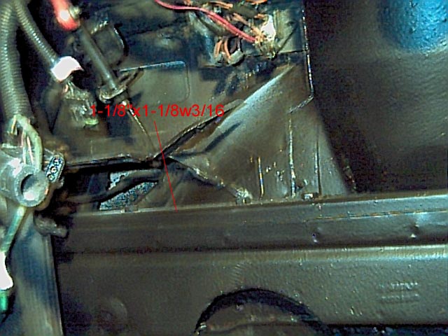
The frame modification A small portion of the frame needs to be cut out on the passenger side. The first thing one needs to do is take harmonic balancer off the engine and throw it away. It is giant and too big to use without cutting all the frame rail. One needs to purchase an ASP under drive pulley for the LS1 corvette( PN:ASP941020) about $200 ( not the one for the f-body) the corvette pulley has the same diameter of 5" but is .75" shorter than the f-body version (a mile in engine swaps). Then I cut out the part of the rail that still interferes with the pulley. For reinforcement I bolted in 1 1/8" o.d. Square steel tubing with a 3/16" wall thickness. It does need to be carved around the strut tower. To prevent the tube from collapsing where cut I placed pieces of 3/8" pipe cut to size . It also needs to be bolted down its entire length (quite a pain) the nuts are inside the frame rail. The only access is through the hole I had just cut for the pulley. To do this I super glued nuts to washers this allowed me to hold the nut with a boxed end wrench without it falling through. It probably ended up taking better than 4 hrs to get them all. I also used green locktite so they should never come out.
IP: Logged
11:54 PM
LS1swap Member
Posts: 1181 From: McHenry,IL.USA Registered: Jan 2001
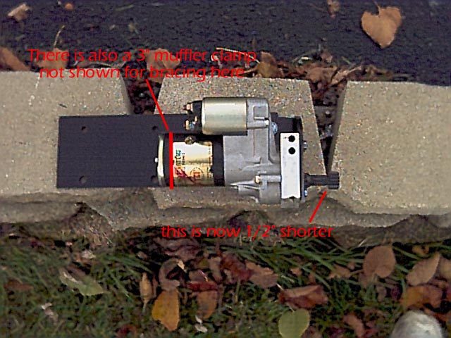
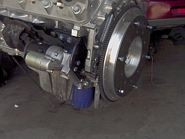
The starter was one of the harder hurdles to overcome. The wide pan was once again the problem, and the fact that the oil filter mount is part of the pan. It can't go where it originally was for the rear axle now goes there. So I had to move it to the other side. My solution was to mount it to the side of the block, and extend the pinion gear to catch the ring gear. I have since used a shorter version by about a 1/2" I don't have any pictures of this yet but I will post them when they are developed. but it works great just as it is. I did need to do some shimming to get the gear lash right, and it takes some care and skill to get the alignment correct. Orvil came in from the back side on his set up and had the starter spin in reverse. Just a thought I have no idea which way is better
IP: Logged
11:59 PM
Oct 3rd, 2002
LS1swap Member
Posts: 1181 From: McHenry,IL.USA Registered: Jan 2001
The axles are stock length. The only change was to the passengers side tripot joint. I used a type 1 instead of the stock type 3. The type 3 would probably work too. but it has a chamfered end and would need to be machined flat to hold the retaining clip properly. I had to use a 168 tooth flywheel for starter engagement. If I was just to use the stock tripot joint in the stock position it would hit the ring gear. Not good LOL. So I moved the tripot joint out about 3/16 ". I accomplished it by moving the clip to the end of the tripot joint instead of in the normal groove. To hold it in place. I drilled and tapped the end of the shaft for a 5/16" bolt ( use a good cobalt drill bit and even at that plan out going through a couple the axles are case hardened). I also used green locktite to assure it never comes loose. I used two 5/16 grade 8 washers filed down to the same thickness as the usual groove as a spacer to let the clip slide free. I then splined a 3/8" washer for the end. Not as hard as it sounds I just bolted the washer to the end of the shaft and used it as a guide to spline it with a small three sided file. The washer had an O.D. Of 1.120", and the outside of the splines had an O.D. Of 1.126 " so they were pretty close to start with. The carriage bolt also had a 3/8" square shank so this worked out good for keeping the washer centered. In addition I used a set of Rodney's axle stabilizers/seals. This worked out great for me for the tripot is moved out about 3/16 and rodney's bearings move the seal out about 1/4" so the seal rides in approximately they same place as it originally did.
IP: Logged
12:02 AM
LS1swap Member
Posts: 1181 From: McHenry,IL.USA Registered: Jan 2001
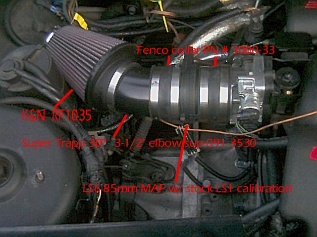
The intake is pretty straight forward. I just rotated it 180* from its original orientation. I did need to lengthen the wires that go to the MAP sensor, and fold the ones that went to the throttle body back. (very easy) the pic shows the parts need for the rest of the intake.
IP: Logged
12:05 AM
PFF
System Bot
LS1swap Member
Posts: 1181 From: McHenry,IL.USA Registered: Jan 2001
Oil pressure sender I used the stock oil pressure sender from the Fiero. I found an Metric Adapter Kit from the AutoBarn.com " Equus Oil Pressure & EQU6848 $5.99" the thread size is 16mm x1.5 very unusual. As a bonus in the same kit it had an adapter for my after-market water temp sender as well. I had to use a couple of brass pipe fitting to make it all work , but it is pretty simple to figure out.
IP: Logged
12:07 AM
LS1swap Member
Posts: 1181 From: McHenry,IL.USA Registered: Jan 2001
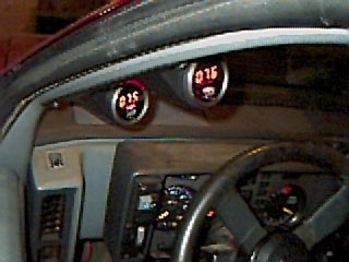
Water and oil temps The PCM uses the stock sender for its reading. For me I added a after-market sender in the opposite head. The LS1 also has a provision for a oil temp sender just above the filter. The part is un drilled and threaded in the f-body part but is easily modified. I used a dual pod gauge mount from the Fiero store ( took a little bit of filing to make it fit perfect, but very close from the start. The gauges are from CSI summit part number CSI-1225)
IP: Logged
12:09 AM
LS1swap Member
Posts: 1181 From: McHenry,IL.USA Registered: Jan 2001
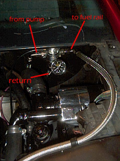
I used a remote pump by meziere. It is electronically controlled by the CSI digital gauge. It can be set from 100-300* F I have the pump come on at 103* so I am basically running without a thermostat. It actually is running too cold right now and barely ever gets over 170* (too cold for an LS1) I had to make some adapter for the front of the block here is an e-mail from meziere
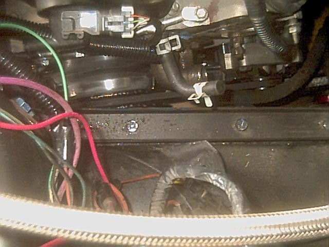
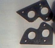
The WP116 should do the trick. On the LS-1 the lower holes are where the water enters the block and the upper holes are where the water returns to the radiator. I would guess you will make a plate for each side with two hole in each plate to correspond to the holes in the block. The water will flow from the bottom of the radiator to the center port on the remote pump. The water will exit from the two side ports of the pump and go to the two lower holes in your block plates. Usually two #12AN lines are used for this. The water will exit from the two top ports and from there you may need one of our Y-Blocks to merge them into one hose to go back to the radiator. The Y-Block can be found on page 22 of our latest catalog. I hope that helps. Please let me know if you need anything else. Sincerely, Don Meziere I also tied in the heater hose and vapor vent line from the heads into one of the return lines. The pump is mounted to the battery tray with a bracket I fabricated ( the picture was for another thread about fuel regulator, but shows the pump very well
here is a pic of the plates I made
[This message has been edited by LS1swap (edited 10-04-2002).]
IP: Logged
12:24 AM
LS1swap Member
Posts: 1181 From: McHenry,IL.USA Registered: Jan 2001
As far as the wiring that all depends on which year PCM you buy so it would do little good to go into that. The only other thing I can think of at this time is that I also replaced the fuel pump with one that is made for a 96' corvette ( a direct replacement thanks! Will) I am not going to pretend this is a complete set of instruction, but it does give a good over view. A person with a good amount of mechanical skills could do this swap. Expect to pay at least $3000 plus the engine to do this swap on your own. I would also be happy to e-mail the CAD files to any one interested.
IP: Logged
12:38 AM
Nashco Member
Posts: 4144 From: Portland, OR Registered: Dec 2000
Thanks! Everyone and yes I spent half my time measuring things to see what would fit and what wouldn't. I would be glad to help anyone. Now if only I could get PIP to work again for me I will continue this. I still have the exhaust manifolds, a list of part numbers, and a few odds and ends to deal with
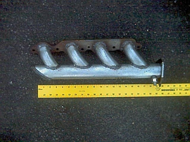
to continue... The exhaust manifolds are kind of a specialty item too. The back one is off a 2000 T/A, and the front one is custom made. Fortunately GM makes a flange for this purpose Pn# 12480130 I needed two. One to make the manifold the other was used as a spacer to move the rear manifold out to clear the rear engine mount being moved up about an inch.
[This message has been edited by LS1swap (edited 10-04-2002).]
IP: Logged
08:48 PM
Will Member
Posts: 14303 From: Where you least expect me Registered: Jun 2000
I've heard that Archie did one LS1 swap. I'd like to hear his take on installing it, just to see how differently the two of you went about doing the same task.
IP: Logged
09:38 PM
Oct 4th, 2002
LS1swap Member
Posts: 1181 From: McHenry,IL.USA Registered: Jan 2001
I have heard Archie is working on the swap..... I don't know if he has completed it or not. Not claiming to be a know it all, but I would be more than happy to drive my car to his shop. Put it on the lift and explain the whats and whys of my swap. I would love to see a kit made for the LS1
IP: Logged
10:42 AM
PFF
System Bot
Oct 5th, 2002
BlkBird Member
Posts: 409 From: Moscow Mills, MO, USA Registered: Sep 2002
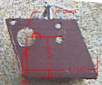
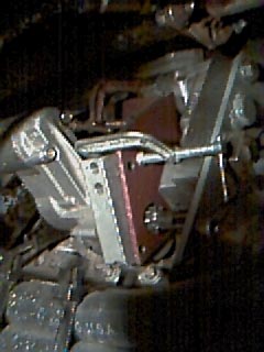
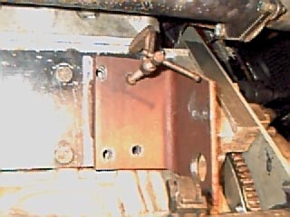
By a couple of emails I see there is one area I did not go into enough detail on. It is setting the gear lash on the starter. (By the way I originally did this with the engine out of the car, and the trans wasn't mounted yet either. But I did not take any pictures of it so that is why I am showing doing it while the engine is in the car. I would not do it with the engine in it would make it much harder). Here is how I went about it. I started with a 3 1/2" x 3 1/2" x � thick angle iron. I then drilled a 1" hole (as dimensioned in the pic 1). I then C-clamped the starter to the bracket and to the plate on the block (as in pic 2),. (I did this with the motor of the starter off). This makes it much lighter and easier to handle. I had to do this anyway to install the pinion gear and rotate the mounting block. You will need to tweak it around a little to get the right gear lash. You can pull the pinion gear out and look from the flywheel side to see if it is ok. While still in place drill through the bracket into the starter block ( use a minimum of three bolts to hold it to the bracket). Then you can undo the C-clamp on the starter and tap the starter block for threads. Now that the starter is off you can drill through the bracket into the plate that is mounted on the block (as in pic 3).( BE CAREFUL YOU ARE DRILLING TOWARDS THE ALUMINUM BLOCK) it is best not to drill all the way through the plate while it is on the block. Take the plate off to Finnish drilling. If I was to do it again I would weld nuts to the back of the plate to facilitate easier shimming. Speaking of shimming I would set the gear lash a little tight to start with for it can be shimmed out. If it is too loose you would have to start over . I also would drill a 1 � " hole instead of the 1" one I did. For the start has to go in at an angle when being mounted to clear the motor mount and the pinion gear wont fit through the hole that way. (you can tell the hole has been reamed in pic 1. I hope this helps a little and makes I little more sense of how it is accomplished
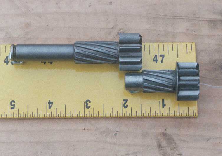
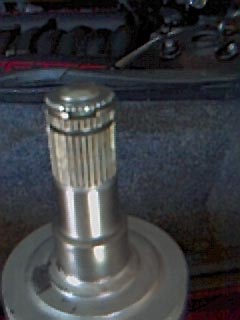
New starter pinion extension.... The powermaster pinion already has a hole in the end for centering the shaft. Here is the close up
[This message has been edited by LS1swap (edited 10-14-2002).]
IP: Logged
06:23 PM
Oct 13th, 2002
LS1swap Member
Posts: 1181 From: McHenry,IL.USA Registered: Jan 2001
I was asked in another thread what the swap cost me so I thought I would list it here
$1,500 LS1 engine with 47 miles $287 98 PCM PN#16238212 used $255.49 engine harness stick PN# 12177561 gmpartsdirrect.com $87 00' exhaust manifolds used $18.20 each Exhaust manifold flanges two needed PN# 12480130 GM $159.95 LS6 MAF/IAT with LS1 calibration PN# pac8411f paceparts.com $359.99 LS1 aluminum flywheel PN# FIDAFLS1 fasttoys.com $165 for flywheel mod and balancing $284.95 corvette undredrive pulley PN# ASP941020 fasttoys.com $260.69 Mezere polished electric water pump PN# wp116u Summit $79.95 CSI water temp digital gauge & relay CSI-1225 summit $85.52 96 corvette fuel pump PN# 25163464 gmpartsdirect $26 strainer for pump $74.95 Mallory fuel press. Reg. MAA-4309 summit $272.00 86-88 v6 5spd kevlar clutch kit 54003R Fiero store $69.95 84-87 poly cradle bushings 57502 fierostore $90 Adapter plate steel and aluminum $50 CNC machining for plate $80 Rodneys axle bearings $250 TCI Hitachi style mini starter and mod $10 VATs box lmm555 timer resistors, and capacitor $100 about for welding $400 odds and ends ( bolts ,nuts, gaskets, ect.)
$4,984.84 total.... minus engine total $3,484.84
Things not really needed but I wanted anyway
$40 Engine covers 12556455 12559261 gmpartsdirrect.com $20 Fuel press gauge jegs $200 Russell's fuel lines and fittings $79.95 CSI oil temp digital gauge & relay CSI-1225 summit $199.99 super mini 74 amp Alt. 358-2002 jegs ( not needed the Fiero alt will fit just fine) $35 gas lift strut for deck lid
$5558.79 total with add ons minuus engine total $4,058.79
Things I want but don't have yet $???? Paint $500 estimate on exhaust (not done yet I am leaving it off for I may have the front manifold jethot coated) $??? Struts & shocks $??? wheels and tires $300 LS6 intake $600 about for Mr. Mikes seats $????? Total.... the money pit never ends LOL but it is a hobby and hobby's cost
IP: Logged
10:53 AM
LS1swap Member
Posts: 1181 From: McHenry,IL.USA Registered: Jan 2001
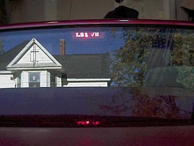
On a side note I did a little mod on my third break light so all you locals will know when you are behind me at a stop light my $19 digital camera dosn't do it justis , but here it is
IP: Logged
10:59 AM
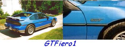
GTFiero1 Member
Posts: 6508 From: Camden County NJ Registered: Sep 2001
I don't have much to say, just wanted to compliment you again on the fantastic documentation! If everybody documented things this well, our cars would be a lot better off.
Bryce 88 GT
IP: Logged
10:18 AM
wiccantoy Member
Posts: 3372 From: northwales , pa / Williamstown nj Registered: Mar 2002
congrats on a great car and an even better thread . this will help many people , you should put all this info on a web page and show a link in your signature.
a few quick question . how does it feel driveing it , any complaints ?
have you had any problems with the final project ?
and with the added weight does it push any more at high speeds in turns ?
------------------ go fast or go home or just drive it like you stole it email cwandall@yahoo.com
IP: Logged
12:42 PM
LS1swap Member
Posts: 1181 From: McHenry,IL.USA Registered: Jan 2001
Yea the exhaust does kind of give the sleeper away LOL I get strange looks at stop light. I think people are not sure whether it is jus a sh*ty exhaust system or if there is more to it.
I would love to do a web page. I actually tried one and there is a link in my sig, but it stinks. I am terrible with computers beyond Auto Cad and lotus word pro.( I used those two 99% time when I am using my PC.) If anyone is willing to help I would appreciate it.
No problems... it is everything I had hoped it would be and more. As far as handling it is too early to tell for I still have the old suspension on it. I may even be original??? But I haven't noticed much difference than the stock V6
[This message has been edited by LS1swap (edited 10-14-2002).]
IP: Logged
06:37 PM
Oct 25th, 2002
LS1swap Member
Posts: 1181 From: McHenry,IL.USA Registered: Jan 2001
Just a littler side note I spun a rod bearing on the #1 connecting rod. It has nothing to do with the swap. I took it out today and saw it. . Oh well I knew $,1500 was too good of a price for that engine. Fortunately that was it on the damage so I should be up and running within the month. I checked in on a stroker kit for her but at 3k I don't think so LOL. But maybe it is time for a little more aggressive cam
[This message has been edited by LS1swap (edited 11-12-2002).]
IP: Logged
09:59 PM
PFF
System Bot
85frankenstein Member
Posts: 687 From: Kenosha, WI 53142 Registered: Nov 2001
Great job on the documentation and pics! Like someone suggested, you might want to put it all in an easy to find website. One of these days, I'd love to check out your wheels in person as when I visit the parents, I'm not far from you at all. They're in McHenry and I know the area real well!
Bob
------------------ As Alice Cooper once said...
quote
Feed My.... Frankenstein!
IP: Logged
10:08 PM
Nov 12th, 2002
LS1swap Member
Posts: 1181 From: McHenry,IL.USA Registered: Jan 2001
I am not sure if it the phases or the moon or what but I have gotten allot of questions on my swap lately. So I thought I would bump this to make it easier to find.
IP: Logged
04:13 PM
May 14th, 2003
LS1swap Member
Posts: 1181 From: McHenry,IL.USA Registered: Jan 2001
Since this is the swap I will eventually end up doing (Lord and Checkbook willing)... I decided to help you out a bit. I cleaned it up and made it a bit more concise and organized... though it was VERY organized to start with.
I hope you like it. If you have any changes to make, let me know. IF there's any corrections or additional info I'll ad it ASAP.
I didn't do much to it... I only spent about half an hour. I thumbnailed the pics so they were easier to navigate. I tabled the costs, cut out other's comments and non-swap related comments.
If you have higher resolution pictures, I would be more than happy to replace the smaller ones.
MAN, I want to do this swap... but the lack of a garage (and welding experience) keep me from starting.
I'll wait for DKOV's 6 speed HD tansmission to come out before I start collecting parts.
------------------ 1988 Fiero GT T-Tops - IRM rockers soooooon. 1999 Infiniti I30t Turbo (336 HP at the ground) 1999 Eclipse GS-T Spyder Super 16G Turbo(Wife's Car... not dyno'd yet)
IP: Logged
04:40 PM
LS1swap Member
Posts: 1181 From: McHenry,IL.USA Registered: Jan 2001
Wow I am impressed. I wish I knew more about web design and could do that kind of stuff. I tried to do something like that but gave up after I realized that I just didn't have the knowledge. It is in my sig, but I should remove it for it is very poor quality and incomplete I do have allot more pictures... Many high resolution. I have a whole roll that I never even developed..... I will have to send them to you.
A garage probably is needed, but as far as welding I didn't trust mine either. I just tacked the parts that needed welding together and then took them to a local shop. I did work as a metal fabricator for about six months when I first got out of high school, but I mainly did design, cutting, and forming. Not too much welding.
I agree about the six speed, or just a taller fifth...... You get up to about 75 and you want to shift again but there is no where to shift to LOL
IP: Logged
09:39 PM
Jun 12th, 2003
breakneck88 Member
Posts: 265 From: Chambersburg P.A. Registered: Feb 2003
Great swap! Whats your regulator PSI? I'm building a 3800 SC and using custom fuel rails and have a 50 PSI regulator with almost the same setup as that. One line feeding it. I think the brand of my regulator is a mallory.


 . I also would drill a 1 � " hole instead of the 1" one I did. For the start has to go in at an angle when being mounted to clear the motor mount and the pinion gear wont fit through the hole that way. (you can tell the hole has been reamed in pic 1. I hope this helps a little and makes I little more sense of how it is accomplished