Pennock's Fiero Forum
  Technical Discussion & Questions - Archive
  Zumalt Kit Design Elements Consolidated

T H I S   I S   A N   A R C H I V E D   T O P I C
  

Email This Page to Someone! | Printable Version


Zumalt Kit Design Elements Consolidated by FieroGTS
Started on: 04-04-2002 02:17 PM
Replies: 13
Last post by: FieroGTS on 04-04-2002 10:32 PM
FieroGTS
Member
Posts: 200
From: Tampa, FL, USA
Registered: Feb 2002


Feedback score: N/A
Leave feedback

Rate this member

Report this Post04-04-2002 02:17 PM Click Here to See the Profile for FieroGTSClick Here to visit FieroGTS's HomePageSend a Private Message to FieroGTSDirect Link to This Post
I figured I would consolidate Archie's posts from his thread Zumalt Kit Design Elements. located at
https://www.fiero.nl/forum/Forum2/HTML/019134.html

Below are chapters 1 through 6 and two addendums to the story. Chapters 1 to 6 are Archies words exactly. The Addendums are Kerry's words.

This should make it easier for anyone just tuning in.

[This message has been edited by FieroGTS (edited 04-04-2002).]

IP: Logged
PFF
System Bot
FieroGTS
Member
Posts: 200
From: Tampa, FL, USA
Registered: Feb 2002


Feedback score: N/A
Leave feedback

Rate this member

Report this Post04-04-2002 02:18 PM Click Here to See the Profile for FieroGTSClick Here to visit FieroGTS's HomePageSend a Private Message to FieroGTSDirect Link to This Post
Zumalt V8 kits Design elements. Consolidated


Chapter 1

]These 1st few paragraphs are going to hard to write because I'm going to be discussing a subject that I know a lot about and I want it to be told in a way that is both fair and accurate. So please bear with me while I try to get thru these first few paragraphs. As you hear the story, you will realize why these first few paragraphs are so hard to get right.

This is a difficult post for me to get worded right. I want to offer you guys some facts here and tell you a true story that you would never believe if someone else told it to you. I want to tell it in a way that you don't think that I'm trying to be self serving. I've been working on Fieros for 16+ years now and I hate to say this but V-8 Fieros ARE my life, I really have no other serious interests. When you have spend the kind of time on this one subject as I have in the last 16 years you meet a lot of people, hear a lot of stories, and gather a lot of information that many others would consider worthless. Today I am about to start sharing with you more information about V-8 Fieros than you may ever have imagined existed.

Currently there is another thread on this Forum that asks about the HTD V-8 Engine conversion kits. https://www.fiero.nl/forum/Forum2/HTML/019020.html I was participating in that thread and the questions of why certain things were done the way they were in the various V-8 kits came up. We talked about design & engineering developement and reasons why certain V-8 engine conversion kits shift the engine to the left in the car and and other technical questions.

At one point during that conversation I submitted that I could explain the apparent lack of common sense in the engineering of certain V-8 kits and others' in that thread expressed an interest in hearing just how a V-8 kit can be developed that had engineering problems.

That other thread has several people sitting on the edge of their seats ready to fling arrows at each other and I truely want this discussion to be about sharing some interesting information rather than become a flame war.

It will take several days and hours of typing for me to tell you this whole story. I swear that if this turns into a flame war, I will just keep all this to myself as I have kept it to myself for many years already.

Ok, now that you have gone and read the other thread, you should know the subject matter that was being discussed there.

Let's see if we can get this off to a smooth start.

From time to time, here on PFF and in other forums, the topic of the Zumalt V-8 engine conversion kits comes up. As part of those kinds of threads it always turns into a discussion copmparing my V-8 conversion kit to what has been known as the Zumwalt kit. Yes, I know, I'm mis-spelling the name Zumalt. I started doing that a long time ago and I did it on purpose. Wether is be Zumalt or Zumwalt we are all talking about the same thing. Many times in this thread I'll also call it the Z kit. You'll also notice that in this post and many others, I've always refered to the Zumwalt kit as "what has been known as the Zumwalt kit". When I have finished typing tonight you may want to consider re-naming that kit.

NOW... at this point it needs to be understood Right up front everyone needs to know that the HDT kit, the Fiero Plus kit, the Shelby kit the old Corson kit and a few others are direct and exact copies of what is known as the Zumalt kit. You don't have to take my word for it I can prove that to you later. In fact it also should be understood that I can prove everything I'm going to be telling you here.

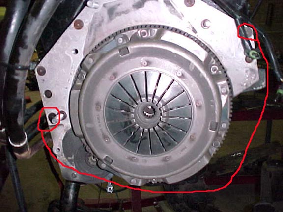
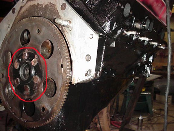
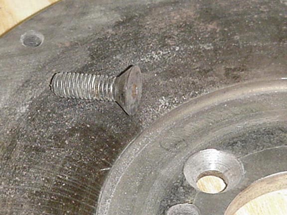
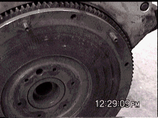
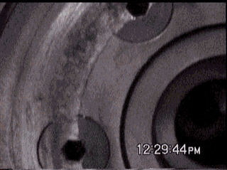
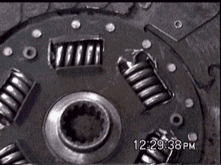
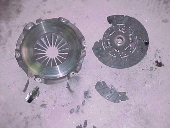
In page 2 of the other thread I refer to above the question of the design of the Flywheel and clutch and the reason for the 2" move of the engine came up and I responded with a few statements that led to the developement of this thread.

If you haven't read that thread yet you should go read it now. Don't bother to read the flames in that thread, just read the facts and opinions that are expressed there.

I'm sitting here waiting for you to finish reading that right now. da da da da da de de de de....... ok Welcome Back.

The 1st part of this story I had heard 2nd hand about 12 years ago. I wrote it off because there was no easy way to confirm it. Then back on 7-14-97 I had the story confirmed in writing by 2 of the three people who were actually there.

So here we go....

To understand the elements of design that led to the moving the negine over in the engine compartment and that cause the clutch/flywheel problems touched on in the other thread it is necessary that I tell you the whole story about the last 15 years or so of the kit known as the Zumwalt kit.

To understand the design elements you need to how this kit came into being, you need to know the History.

About 15 years ago 3 people got together to put together a V-8 Fiero. They all lived in the Kansas City Area. Doug Jones was the guy who financed the project and made some payments on the donor car when Gary got behind. Gary Zumalt who owned (or was making payments on) a Red 1985 Fiero GT automatic car. & J.D.Michael who owned a company called Econo Race Cars and had a 30,000 sf work area, J.D. was the designer/builder.

You'll recall that earlier in this post I said that I had heard a story about the Z kit many years ago and couldn't confirm it. You'll also remember that I finally got confirmation in 1997. That mail came from Doug Jones and at that time he gave me permission to use his EMail when I saw fit.

To tell this story about the initial design of the Z kit accurately, I'm going to post one of his EMails in it's entirety. I'll let him tell this part of the story.....

Subject:
Gary Zumult
Date:
Tue, 15 Jul 1997 16:53:17 -0500
From:
Doug <doug@awiz.com>
To:
v8archie@v8archie.com
CC:
cd156@usa.net


Archie,

I just got a CC of and an Email Clif Daniel sent to you and your reply. My name is Doug Jones and I am the one who financed Zumult when he needed the money the most --- the bank was getting ready to repo the V8 fiero. I did'nt know Gary very well however JD and me are good freinds. I made the payments on the Fiero and also provided $500 here and a $1000 there when needed. I hauled the Fiero on my trailer to car show. For my efforts I was to get a "piece of the action". No, I never received a thing for my efforts. I own Independence Electronics Inc http:\\www.awiz.com and I am the one who re-calabrated the tach to work with 8cyls instead of 6. Yep, a lot people got screwed over that V8 Fiero kit. In particular the man that developed it...J. D. Michael. JD owns ECONO RACE CARS and had a 30000 sq ft building in the limestone mines here in Independence Mo. He furnished the space, tools, and the engineering expertise to make the V8 Fiero a reality. $3000 won't make or break me, but JD put uncounted hours and
resources into that kit with the promise of fortunes to be made and got NOTHING in return. He could have been making money instead.

What happened?? In 1986 or 1987 JD was diagnosed with TB that he apparently caught in the 60's while serving in the Air Force in Vietnam. While JD was at the VA hospital getting treatment, Gary decided to go down to the shop and abscound with all the prints, drawings, patterns and the car. JD was too sick to do much about it. There were no written contracts that I know of. Everything was done on a handshake. Pretty shity thing to do to a friend, huh? Gary must have forgot about the Hot Rod Magazine article due
out in October 1987! I'll explain that later.

JD is a well known and talented dragster chassis builder. Him and I have
been freinds for years. Among many other things, JD made a pretty impressive tubular dragster chassis kit. He sold a few but lacked the financing to market it properly. The V8 Fiero kit was to be the golden
goose-free advertising in Hot Rod Magazine etc. -- but Gary ate the goose
rather then wait for the golden egg.

You may remember the Hot Rod Magazine article from October of 1987 promoting JD and Gary's V8 Fiero kit. Oh boy, the power of a national magazine!!! JD's phone number and address was in the article - Gary's was
not. JD got STACKS and STACKS of mail from people begging to buy the kit!! The phone rang off the wall and, considering the circumstances, were a source of aggravation to JD. People even sent money to pay for mailing a catalogue. And we did'nt have a kit to sell them! Wish we had known of you
at the time! The phone number is no longer any good but he still occasionaly gets an inquiry by mail. Of course Gary never got ONE of those leads! (JD also got some hot calls from customers looking for Gary.)

When one has stacks of inquiries in-hand it's pretty easy to get the money to fill the orders. A freind of mine, Roger Porter, saw the stacks of mail and offered to totally finance the project. We decided to buy a wrecked Fiero so we could get started re-creating the patterns. Unfortunatly JD's
TB and the medicine he was taking was beginning to take the wind out of his
sails. We decided it would be too much for him to take on the V8 fiero project at that time. We never pursued it again. A few years later JD moved the race car business from the large limestone mines to a workshop he built
at his home in Raytown Mo.

I just called JD and read him this Email to confirm my recollection of the V8 Fiero fiasco. He approves of this Email. At this time he has no interest whatsoever in even talking about the V8 Fiero.

I thought you would like to get the real story from the principles involved. This comes from the "horses mouth". I guess you know which end of the horse Gary's version would come from.


Doug Jones
Doug Jones, President
Independence Electronics Inc
119 S Main
Independence, Mo. 64050 USA
Phone: 816-836-1094
Fax: 816-252-7309
Internet: http://www.awiz.com

Tomorrow, we'll talk about how that initial design of an Automatic only kit evolved into a stick shift kit that has as many engineering issues as we've seen discussed many times.

Archie

IP: Logged
FieroGTS
Member
Posts: 200
From: Tampa, FL, USA
Registered: Feb 2002


Feedback score: N/A
Leave feedback

Rate this member

Report this Post04-04-2002 02:19 PM Click Here to See the Profile for FieroGTSClick Here to visit FieroGTS's HomePageSend a Private Message to FieroGTSDirect Link to This Post

FieroGTS

200 posts
Member since Feb 2002
Chapter 2

Yesterday we talked about the early history of the kit known as the Zumwalt kit. I find it quite interesting that when JD Michael designed that kit he did it on an automatic car. While I built my 1st V-8 car as a stick shift. I think you'll find that to be a pretty important distinction as we move thru the developement of that kit.

The configuration of their V-8 at the time that Gary took off with it was that it was an automatic car and the engine/transmission assy. had been moved to the left in the car. Over the last few years I've talked with Gary's old partners several times via phone and EMail. During these conversations I had the occasion to discuss in detail the original configuration and I learned several things. JD had built the car as a prototype and he never intended it to be a final production design. He had wanted to modify several aspects of the original design to eliminate a few design "wrinkles" that had appeared during building & testing. At about the time that JD went into the Hospital they had been planning to re-build the original car to make it into a properly engineered final product. Before those changes could be made Gary took off with the whole project.

Now you'll recall that I said JD had moved the engine/transmission to the left in the car. I remember when that article came out in the magazine. I looked at those pictures real close and then I'd look at the V-8 car I was driving and it didn't take long to determine that the engine/trans. had been moved to the left in the car some 2". I hadn't moved mine to the left in the car & it took me a few hours to realize the reason that JD & I could do it in different ways and both still be right.

What!!!, did Archie just say that one of the design elements on the JD Michael kit had a design element that was done right????

Yeah, when each one of us was designing our kits independantly, neither one of us were thinking about the considerations of making the kit for another type of transmission.

Let me explain... JD did a kit for an automatic car. If you go out and take a look at the left end of the automatic transmission in the Fiero, you'll see that it has more than 2" it can move to the left in the car before it has a clearance problem with the left frame rail. Think about this for a minute, just stop and think. Put yourself in JD's shoes.... here you have a SBC bolted a Automatic transmission... you're trying to find a place to put it in the Fiero. The engine has the Chevy HBP & pulley on it & the W/P (WaterPump). The HBP, pulley & the W/P are hitting the right side frame rail heavy. Rather than cut the right side frame rail to clear the pulleys, let's move the engine to the left in the car a couple of inches and not have to trim either frame rail.

I hope everyone understands the story to this point because I'm going to ask you to remember the following statement because later it's going to quite important in the evolution of the axle, F/W & clutch problems that the kit now has. This is the line to remember "Rather than cut the right side frame rail to clear the pulleys, let's move the engine to the left in the car a couple of inches and not have to trim either frame rail."

On my Stick shift car, I was a lot like JD because I didn't want to cut the frame rail either. BUT, I started out with a stick shift 4 speed car. ....PAY attention here.... Go out and check your car & you'll find that the left end of the Fiero stick shift transmission is real close to the left side frame rail. I would have liked to use the original SBC pulleys and W/P drive setup on the front of the engine, but I knew that I'd have to notch the Right frame rail to clear it. And, as close as the transmission is to the left frame rail, I knew that if I moved the driveline to the left in the car I would end up notching the left side frame rail. You see, on a stick shift Fiero you either had to leave the eng/trans in the original location and notch the Right frame rail or you could move it over to the left and notch the Left side frame rail. My question about the Zumwalt Stick shift kit all these years has been "If you know that you have to notch ONE frame rail, WHY IN HE!! would you choose to move the driveline to the left in the car notching the left frame rail AND ADD THE EXPENSE OF MAKING CUSTOM LENGTH AXLES???"

I tackled the problem by developing a 3rd. choice. I designed a mount system and pulley system that would leave the engine in the stock location & drive the W/P WITHOUT CUTTING EITHER FRAME RAIL.

You see JD never had to make that decision because he had an automatic car and it was easy to move the engine over without frame modifications.

Ok, It's close to bedtime now.....

Now you know that when Gary took off with JD's design it was an automatic ..... how did it become a stick kit? Who did that engineering? Gary Zumwalt?

Don't bet on it.....

Tune in tomorrow.

Archie

IP: Logged
FieroGTS
Member
Posts: 200
From: Tampa, FL, USA
Registered: Feb 2002


Feedback score: N/A
Leave feedback

Rate this member

Report this Post04-04-2002 02:20 PM Click Here to See the Profile for FieroGTSClick Here to visit FieroGTS's HomePageSend a Private Message to FieroGTSDirect Link to This Post

FieroGTS

200 posts
Member since Feb 2002
Chapter 3

Well, let's see, has everybody had time to go out in the driveway and take a look at their Automatic &/or Stick shift Fiero to see how far the tramsmission can be moved to the left before it hits the frame rail?

As you know by now, this is about how the kit known as the Zumwalt kit got from the reasonable design that JD Michael put together to where it is now.

You also know by now that the original automatic car that JD put together was intended as a prototype only. A few features of that kit were to be redesigned before JD (the engineer) was ready to mass produce kits for sale.

So that's where we take up tonight.

When Zumwalt took off with the car, drawings and plans, he took them to a machine shop and had several sets of parts made up. These parts were exact duplicates of the parts that JD had put on the prototype car. The automatic versions of these kits still have the same design to this very day.

Ok, so when Z started selling kits they were for automatic cars only and he started on his merry way. When JD had developed the original car he had Moser Engineering out of Portland, Indiana doing the custom axles and J.R. Headers had tooled up to make custom headers for him.

Remember now, we are trying to follow the developement of that design and what happened to get it to where it is today.

When Gary 1st. started making those kits he used the same sources. Both Moser and J.R. Headers had company policies back then where they would make and send parts to new customers by "COD CASH Only" and then after the First order they would sell "COD Company Check Ok". (you're gonna ask how I know this story, so hang on I'll tell you in a minute) (AND Yes,this story does have a LOT to do with the goal of this thread) Anyway Z ordered an initial order from both of these suppliers of several sets of parts. They shipped them "COD CASH Only" and he paid it. The second order from these suppliers was a very large order and they shipped the parts "COD Company Check Ok" & you guessed it the bill got paid with a very bad check.

Now, before I tell you what happened next in the developement of the "Z" V-8 kit, I have to tell you how I know the above story since I was not buying parts from either one of those suppliers. So this is a side story and don't forget where we left off. Ok, you'll find this funny in a way. A year or so after I began selling my V-8 kits I put a small ad in Popular Hot Rodding Magazine. About a month after the 1st ad had appeared, I got a certified letter from a court in Kansas City informing me that I was being sued for $18,000 by these 2 companies. When I read the suite it appeared that they thought I was part of the Zumwalt entity and that we had just changed the company name to dodge the bills. Evidently both companies had discovered that they both had been ripped off and they joined forces to find Mr. Z and their money. I had to travel over to K.C. and conference with the lawyers and take paperwork to convince them that they had the wrong guy.

Ok back to the original story.

Zumwalt seeking to avoid those suppliers had went "underground". While he was on the lam so to speak, a guy in Arizona named Randy Corson obtained one of the automatic Z kits. I remember Randy use to brag to people that he hadn't had his hands dirty in 20 years. He was not an engineer and in fact he wasn't involved in working on cars at all. Here is where JD's vision went to he11. Randy took the Z kit to a local machine shop and told them to make ?? number of copies of it, and he told them that while they were at it they should make some flywheels for a stick shift version too. They were a michine shop and not an automotive shop and they didn't even have a car to work on when deciding on a F/W design or anything. (the Corson part of this story was related by his wife to someone I cannot name right now at the 1989 Kit Car Run & Gun) So the flywheel for the stick version of what is known as the Zumwalt V-8 kit was actually designed by someone working in a machine shop and it was never tested in use until sometime after it was produced in quantity. Corson never built more than 3 V-8 cars himself, well he didn't build them, he had a local auto repair shop assemble them for him. So, in reality, that kit usues the same adapter plate for both the stick shift and the automatic versions & no one actually designed & tested the F/W to work on this V-8 swap. The Flywheel was just designed to fit within the envelope that the already existing parts provided. We'll look at the F/W, adapter plate and several other of these parts later in this thread. Ok, so at this point Corson has a direct copy of the automatic kit designed by JD Michael and a version of that kit with a stick shift flywheel made to fit within the confines of a bell-housing that originally had carried a thin flexplate. That's why the flywheel is so thin to this very day.

Ok, so after Corson had invested in a couple dozen sets of the stick shift version of the parts, he had a local shop assemble his 1st stick shift car for him. Remember on day 2 of this thread, I told you to remember a statement for future reference? That statement was "Rather than cut the right side frame rail to clear the pulleys, let's move the engine to the left in the car a couple of inches and not have to trim either frame rail." Well Randy never even thought of this statement until after he had a bunch of money invested in custom length axles for the never before assembled stick shift version of the kit. As he found out when assembling the first stick shift car, they had to cut the left side frame rail. Before this point, He had never even compared the size of the stick shift transmissions to the automatics. He ended up with a large iunventory of kits that in effect moved the engine to the left in the car to avoid right side frame rail cutting and ended up cutting the left side frame rail instead. If he would have done a little bit of research and engineering before manufacturing parts, he would have realized that since he was going to have to cut one frame rail anyway, why not cut the right side frame rail and save the expense of having to supply custom length axles with his kits.

So what does he do now? Does he go back and correct the problem and make it so that the customer doesn't have to pony up for custom length axles? No, that would be too much money invested and lost. Instead he started telling people a story that is still being told by his successors even today. He just told everyone that would listen that the stock Fiero axles would break with the power of a V-8 and the customer needed these axles because they were stronger than the stock axles.

So now you ask, how did Zumwalt get involved in this again.

Well at some point his creditors finally did catch up with him and made provisions to collect from his. Since he then had to pay off his old bill then why stay underground. Gary came back and, in the spirit of "turn about is fair play" the first thing he did was to make a copy of Corson's stick shift version of his (JD's) kit. Gary figured that Corson was a big shot high profile guy who got all kinds of print in the magazines. Surely Corson had properly engineered his stick shift version of the kit. Gary did the same thing Randy had done and made up a bunch of stick shift kits before he realized the difference between the stick shift and automatic transmissions.

And so it goes.

What ever happened to Gary Zumwalt? FWIH, A few years ago he got sued by several of his old customers for various reasons and he let it be known in the Internet, that he was no longer servicing, producing &/or selling parts to anyone. And that anyone who was still waiting on parts from him should look for them elsewhere.

So what happened to Randy Corson? Several years ago, 1994 I think, he ceased production of both body and V-8 kits. I heard a few years ago, which was several years after he had quit making them, that he had sold "rights" to his copy of the kit known as the Zumwalt kit to someone. At the time I remember hoping that whoever bought those rights didn't pay much for them as they were not his to sell & everybody and his brother had already copied that kit anyway.

Well I'm tired of typing tonight.

Tomorrow I'll show you some of the design elements that JD was going to correct on the original car and how those elements still exist today. We will also look at the compromises made by Corson and adopted by Zumwalt that still exist yet today.

Night all.

Archie

[This message has been edited by FieroGTS (edited 04-04-2002).]

IP: Logged
FieroGTS
Member
Posts: 200
From: Tampa, FL, USA
Registered: Feb 2002


Feedback score: N/A
Leave feedback

Rate this member

Report this Post04-04-2002 02:21 PM Click Here to See the Profile for FieroGTSClick Here to visit FieroGTS's HomePageSend a Private Message to FieroGTSDirect Link to This Post

FieroGTS

200 posts
Member since Feb 2002
Chapter 4

This pic. reflects what JD's adapter plate looked like on his 1st. V-8 kit.

While it looks like a nice part, looks and function are different things. I've been told that one of the major things JD wanted to correct before production was related to the area identified by the red arrow & line. The problem was that on an automatic car part of the transmission housing passes thru this area and the adapter had to be angled and a chunk of the engine block had to be cut out to allow clearance for the transmission housing.

This is another kit of the Z type that shows the adapter plate bolted to the engine. The place right below the arrow is cut on the engine block to clear the transmission.

Here is a view from the other side of that same assembly. The red line indicates the amount of material that has to be removed from the engine block to clear the automatic transmission housing. The sad thing about cutting this particular chunk out of the engine block is that this area is where the original Chevy starter used to mount. So, in effect, once and engine has been modified to work with this design, it is a dedicated engine and can never be removed from the Fiero to be used in a regular front engine/ rear wheel drive configuration again because the normal Chevy starter mounting area is now gone.

Here is a pic of a Stick shift kit we worked on a year ago, and it has the same angle cut on the adapter plate but doesn't have the chunk removed from the engine block. The interference of transmission to the engine on automatic cars is the reason my automatic kits has totally different adapter plate designed for it. But in the Corson re-engineer of JD's design, he wanted to use the same adapter plate and thus that angle that is not needed for a stick shift car remains a part of the design, even on stick shift applications, to this day. You'll also notice that this angle missing from that area of the adapter plate eliminates one of the adapter to engine mounting bolts, you can see the empty threaded hole in the engine block just below the angled area of the adapter plate.

That also means that the area all the way around the bottom of the engine between the indicated holes (more than 180 degrees) is unsupported.

Another problem that JD had intended to fix was the adapter plate thickness. The thickness originally was 5/8" and the problem was that the torque converter was so thick that. When the converter was bolted to the flex plate, the backside of the converter was right up against the flex plate attaching bolt heads. If you just engineered things so that the converter just touched the flex plate attaching bolt heads then the torque converter fit back into the bellhousing to deeply by about 3/8". I had to repair one of these once that came from Corson (but all of them were the same deal) and Corson's customer had assembled it according to his instructions and just bolted the tranny down and the pressure of the converter against the inside of the bellhousing caused it to crack the trans case. (I still have that transmission at the shop & I'll insert a pic of the cracks here tomorrow. Anyway, on JD's original assembly he had to shave the heads of the flexplate bolts so that he could get the converter so it wasn't too deep into the bellhousing. This is another feature that was never corrected and continues in use today. No matter what is done, the converter, cannot be moved any closer to the crankshaft. Unless the adapter plate is made thicker, the converter will be too deep into the transmission. This picture is of a Zumwalt kit sold in 1995 and assembled by the customer. At least on this one the customer didn't ruin the transmission by not shaving the bolt heads.

You can look at all of the current kits of JD's design and see that the adapter plate thickness is still to thin and you can see that it hasn't yet been corrected.

If only Zumwalt had waited until JD was done with the revisions to the design before he took off with it, You can't help think that a lot of Z's customers' would have been a lot better off & the History of this design would have been a lot better.

Yesterday I over estimated how much material we would be able to cover tonight, so we will discuss the compromises made by Corson and adopted by Zumwalt that still exist yet today, tomorrow.

That don't sound right

Archie

IP: Logged
FieroGTS
Member
Posts: 200
From: Tampa, FL, USA
Registered: Feb 2002


Feedback score: N/A
Leave feedback

Rate this member

Report this Post04-04-2002 02:24 PM Click Here to See the Profile for FieroGTSClick Here to visit FieroGTS's HomePageSend a Private Message to FieroGTSDirect Link to This Post

FieroGTS

200 posts
Member since Feb 2002
Chapter 4A

I had to repair one of these once that came from Corson (but all of them were the same deal) and Corson's customer had assembled it according to his instructions and just bolted the tranny down and the pressure of the converter against the inside of the bellhousing caused it to crack the trans case. (I still have that transmission at the shop & I'll insert a pic of the cracks here tomorrow.


The red arrows indicate the cracks that run almost all the way around the case & the blue arrow shows where the Torque Converter rubbed against the back of the case when he had tried to crank the engine over.

Funny story follows:
He had brought the car to me partially assembled with the engine/trans assy. already sitting on the cradle. Neither one of us knew about this internal problem at the time. When he dropped it off he mentioned that he had tried to crank it over and he had to hook 3 batteries up to it to get it to turn over slowly. hehe...... I know there was something wrong at that point but I thought that he had cranked down the bearing caps too tight or had not lubed the engine up when he had built the engine. Imagine how surprised I was when I saw the actual cause.

Archie

IP: Logged
FieroGTS
Member
Posts: 200
From: Tampa, FL, USA
Registered: Feb 2002


Feedback score: N/A
Leave feedback

Rate this member

Report this Post04-04-2002 02:25 PM Click Here to See the Profile for FieroGTSClick Here to visit FieroGTS's HomePageSend a Private Message to FieroGTSDirect Link to This Post

FieroGTS

200 posts
Member since Feb 2002
Chapter 5

Well we've established that when Randy Corson had obtained a version of JD's original design he turned it over to a machine shop to make it into a stick shift kit. Since Corson wanted to use the same adapter plate that had been used on automatic kits. This left the machine with an envelope that had already been established and inside that envelope they had to find a way to install a stick shift F/W and a clutch & Throw-out bearing. The clutch had to be a low profile and the F/W had to be thick enough to allow threaded holes deep enough to give some grip length to the bolts that would holt the clutch to the F/W. The best was to design something like this is to design the adapter plate AND the flywheel together, but Corson's contractor did not have that luxury. The Adapter plate was a fixed design and they had to work with what was left.

On the original automatic kit, JD had made the flexplate ring gear the same diameter as the original Fiero flexplate. With the adapter plate being a "fixed" design the stick shift F/W would also have to be the same diameter. And with the clutch assy. being the same height as an original Fiero clutch to avoid contact with the inside of the Fiero transmission bellhousing the only variable was the flywheel thickness and design & this is where one of the main problems come in.

Think about this, the clutch can only go into the bellhousing just so far. The clutch is a given height or thickness. The thickness of the area where the F/W bolts to the crankshaft has to be at least a minimum thickness. That leaves only the face of the friction surface on the F/W as the only surface that can be a variable dimension and even that is governed by the clutch height.

If the combined thickness of the clutch and the F/W exceeds the available depth of the bellhousing then the only adjustment that can be made in the design is either a thicker adapter plate or moving the friction surface of the F/W closer to the engine by making the Flywheel thinner.

Thus the Corson F/W was designed with a very shallow step from the friction surface of the F/W down to the hub where the bolts pass thru to bolt it to the crankshaft.

This is a picture of a typical Corson/Zumwalt F/W hub. Notice the shallow step from surface A to surface B.

Here is the kind of step a "normal" F/W would have.

As you know there are a set of springs in the center hub of most street type clutches. If a person was to use a normal Flywheel bolt to attach a F/W with a step as shallow as the one you see here then the center hub springs would hit the bolts immediately.

So to gain clearance in this area the Corson contractor elected to use Flat Head Allen Cap Screws to attach the F/W to the crankshaft.

Today, while Zumwalt and Corson are no longer around you can still see this feature in the current crop of V-8 kits based on the old Z & C kits.

Ok, so what's wrong with using allen head cap screws to hold the F/W on? This will take some explaining and those unfamiliar with machining and automotive methods still won't understand but I'll try. Those that understand True Positioning Tolerancing and machine practices don't need me to explain this to them.

Every Flywheel you will ever see on any application (except this one) will use normal Hex Head bolts to hold the flywheel onto the crank shaft. Using hex head bolts puts all of the load on the underside of the bolt heads and puts no side load on the bolts themselves. The bolts hold the F/W onto the crankshaft and their main purpose is not to locate the F/W radially. Using the flat head allen cap screws whit their cone shaped heads into chamfered holes drilled in the F/W is kind of like putting a wheel onto your car. The 1st. bolt that is tightened down locates the F/W radially and the rest of the bolts don't necessarily make full contact around the chamfer when they are tightened. This has 2 flaws in it's use #1 is that the 1st. bolt is the only bolt that has a chance to hold all the way around it's load bearing surface. #2 The other bolts only make contact into the chamfer on one side and when that point starts to make contact and the screw is further tightened it tends to bend or lean towards the side that is not making contact. For these tapered holes in the F/W to be perfectly aligned with the corresponding threaded holes in the crankshaft, the holes in the crank and flywheel would need to be drilled & tapped all at the same time.

As these cap screws begin to bend over when they are tightened you will find that they bend and later removal is virtually impossible and you'll break a lot of allen wrenches getting them out.

To remove these bent bolts, it's not uncommon to have to weld a large nut to then and try to boost them out with an impact wrench. If you also look real close at this next picture you can see the black wear marks left in the chamfered holes by the uneven contact of the flat head allen cap screws.

As you can imagine, you can solve the shallow hub depth by using a racing style clutch that has no center hub springs but there is no cure for the improper use & substitution of flywheel bolts.

Nite

Archie

IP: Logged
FieroGTS
Member
Posts: 200
From: Tampa, FL, USA
Registered: Feb 2002


Feedback score: N/A
Leave feedback

Rate this member

Report this Post04-04-2002 02:26 PM Click Here to See the Profile for FieroGTSClick Here to visit FieroGTS's HomePageSend a Private Message to FieroGTSDirect Link to This Post

FieroGTS

200 posts
Member since Feb 2002
Chapter 6


So far we've seen JD's original one off design become a mass produced collection of engineering errors many of which are still in production.

I'm sure there are several examples of the Zumwalt/Corson et al kits that are running fine and have stood the test of time. To those people I say bless you. You are either lucky that it stayed together or you are lucky that the person putting it together had the vision to see some of the potential problems and do his best to find a way to address lessen their effect on the final product.

We've looked at shaved bolt heads on automatic kits for clearance on Torque converters, we've seen the damage to a transmission caused by not shaving those bolt heads. We've seen chunks of engine blocks cut away for clearance and missing bolt holes. We've seen compromises made to put 10 pounds of clutch & F/W in a 5 pound bag. We've seen how it developed that the Z/C kits moved the engine over to the left in the car . We've seen and still see excuses that it was moved over to "center" it in the engine compartment & we've heard that the stock axles can't take the power and the new axles were necessary to avoid breakage. All these excuses are to cover-up what is in reality an engineering blunder that no one ever noticed or addressed before copying someone else's' work.

We've looked at how a compromise in the adapter plate & F/W design can cause problems with the clutch.

Please excuse the picture quality. Before I got my digital camera, I used to record everything on tape and these pics were captured from video tape.

In this picture you can see how the springs in the center hub of the clutch disc have touched and worn in the area of the shallow center bolt flange of the F/W.

This particular assembly was taken apart by us to correct a Clutch failure (the 3rd. such failure on this particular car).

The Clutch had a malfunction.

And Failed

I've only had to work on 8 Zumwalt/Corson V-8 kits, 3 were automatics and 5 were Stick shift cars. Each one of the stick shift cars were being repaired for clutch problems or repeated pre-mature clutch wear. Of those 5 cars I've only seen 2 of the Flat head Allen caps screws that were broken off. I've broken several of them taking them out but only 2 of the bolts were broken when I disassembled the engine/transmission assy. So that's only 2 bolts out of 30 that were broken. Both of them, of course, caused clutch failure.

The only clutch you can use on this system without risking failure is a clutch that has no center spring hub like CA Kid has. As far as clutches are concerned, I don't think there is much else that can be said.

We touched on the subject of Axles a couple of times and I've shown you how the Corson version of the kit known as the Zumwalt kit proved that it was not the best of engineering thought that went into a situation where you move the engine to the left in the car to clear the right side frame rail only to discover after the fact that moving it over required the cutting of the left side frame rail. Thus the stick shift axles were a waste of money.

I've had some people ask me "If moving the engine over to the right on a Z/C kit is such a bad idea then why do you (ME) do the same thing on the LT1 swaps?"

Anyone who is familiar with LT1 engines know that the distributor is mounted on the end of the engine on the LT1 and I'm here to tell you that the TOTAL assembled engine length on the LT1 is some 3.5" longer that a "normal" SBC engine assembled engine length. If you just notch the right side frame rail to take all of that 3.5", the pulleys on the right side will extend out into a position where they can interfere with the right side suspension system. So I advise my potential customers that if they choose the LT1 engine they will HAVE to have Custom length axles AND will have to notch the frame rails on BOTH sides. I also advise them that my V-8 kit for a "normal" SBC engine is designed to have NO frame cutting and only a little bit of sheet metal trimming.


Tomorrow we'll try to wrap this thing up and get ready to take your questions.

Archie

IP: Logged
FieroGTS
Member
Posts: 200
From: Tampa, FL, USA
Registered: Feb 2002


Feedback score: N/A
Leave feedback

Rate this member

Report this Post04-04-2002 02:27 PM Click Here to See the Profile for FieroGTSClick Here to visit FieroGTS's HomePageSend a Private Message to FieroGTSDirect Link to This Post

FieroGTS

200 posts
Member since Feb 2002
Reserved for CH7
IP: Logged
FieroGTS
Member
Posts: 200
From: Tampa, FL, USA
Registered: Feb 2002


Feedback score: N/A
Leave feedback

Rate this member

Report this Post04-04-2002 02:28 PM Click Here to See the Profile for FieroGTSClick Here to visit FieroGTS's HomePageSend a Private Message to FieroGTSDirect Link to This Post

FieroGTS

200 posts
Member since Feb 2002
Reserved for Ch8
IP: Logged
FieroGTS
Member
Posts: 200
From: Tampa, FL, USA
Registered: Feb 2002


Feedback score: N/A
Leave feedback

Rate this member

Report this Post04-04-2002 02:28 PM Click Here to See the Profile for FieroGTSClick Here to visit FieroGTS's HomePageSend a Private Message to FieroGTSDirect Link to This Post

FieroGTS

200 posts
Member since Feb 2002
Addendum

[QUOTE]Originally posted by Kerry:
[B]I have been reading Archie's post with great interest, as I was the first purchaser of a Gary Zumalt manual V-8 "Kit" in 1986. At that time Gary indicated he had manufactured several automatic kits but no manual kits. However, he indicated he would have them in a few weeks. My kit came from a batch of six that were made locally by someone with a small machine shop using only manual equipment.
At that time, I drove my new 86GT to JD's shop in the limestone "cave" just outside Independence MO. ( It still has a scratch on the drivers side sail glass where Gary leaned up against the car taking engine compartment measurements)
Gary was the only person I had contact with at the time. I was never introduced to JD even though it was his shop.
The demo car that I rode in was the red automatic with a 406ci V-8 and tunnel ram.
I ordered the manual kit, which at that time was made using a STEEL adapter plate that had been fabricated on a manual mill / drill press and painted flat black. This was prior to Gary offering CNC manufactured aluminum adapter plates. The axles supplied were definitely NOT Mosler quality axles. The quality was borderline at best. They were instead fabricated locally prior to Gary approaching Mosler. The clutch was from a local rebuilder and the flywheel looked like something from a high school shop class.... The motor / trans mounts were made from angle iron and flat plate cut free hand in a band saw. The "installation instructions" consisted of a single page xerox copy, and were not received until several months after the parts were received.
At this time Gary had apparently had his "separation" from JD and was operating out of a one car garage at his mothers house in Grandview MO.
The kit was shipped piecemeal over a period of 6 months, even though it had been paid in full up front. It took three trips to Kansas City before most of the components were finally received.
The kit was never installed, and sat in my garage for several years as I was never satisfied with the quality of workmanship. The countersunk flywheel bolt attachment method described by Archie left me cold. The adapter plate also had several attachment holes drilled off center. The dowel pin holes would not line up.
The kit was ultimately sold to a speed shop in Ohio.
The only exception I would take to Archie's chronology is that at least a few manual kits WERE manufactured locally in Kansas City before Corson got into the act. This fact runs contrary to Archie's assertion that the manual kits had been designed by Corson. Perhaps they "re-designed" what Gary had started. Otherwise, I find Archies comments accurate in all other respects.
As a manufacturing engineer, I had offered to provide assistance to Gary in improving the process and quality of his manufactured components (not the design), but Gary was not apparently interested.
Just thought I would add my first hand personal experiences with Gary and the history of the Zumalt V-8 kits. I haven't seen or heard from him for years.
Probably just as well...

Kerry
Eureka MO


I went back into my Fiero V-8 file from 1986 and found the following information regarding the Zumalt kit that others may find useful:

The starter supplied by Gary was a rebuilt "Mega-Torque" from a rebuilder in Kansas City, however the part number on the starter supplied turned out to be a Datsun starter # S114-254D with an ISO# 047. At the time Autozone offered the equivalent starter for about $125.00

The flywheel ring gear was a Datsun replacement #120C (Republic Brand) also from AutoZone. However the numbers stamped on the ring gear were either 434 or 481. It was a 120 tooth gear.

The V belts used were Dayco 15625

The Water hoses used were Dayco 71012 and 81492. (Only the large half of 71012 was used.)

The radiator hose filler was a Moroso # 63740

The throw out bearing was a Fed. Mogul Bower / BCA # 614009

The water pump pully was a Ford # D20Z-8509-A or #D20E-8509-AA.

The crankshaft pully was a GM # 3755820-BC.

Also, the minimal instructions outline the cutting of BOTH left and right side body rails:

"Left side body rail is cut with front edge 1/8" rearward of existing hole on bottom of rail and extend 8 3/4" rearward to almost join second hole on bottom of rail."

"Right side body rail is cut 10 1/2" long starting 9 1/2" from passenger compartment bulkhead."

So much for moving the engine... on the premise that the body rails did not have to be cut.

Finally, because of the shortcoming of the kit, I actually drew up a set of adapter and flywheel drawings for myself using basic dimensions from the Zumalt adapter, but changing those areas that were of questionable design. For example, the adapter plate thickness was increased from 5/8" to 3/4" to provide more clearance for the clutch disc and increase the flywheel web thickness.
I have JPEG pictures of these drawings if anyone has interest in seeing them and can provide the proceedure to download them to this forum. I used them to manufacture a new adapter and flywheel that I intended to use for a 4.3 conversion and leave the stock length axles.
To those who would like drawings...NO... I will not supply them. These were for my use only and not for commercial use. But, a picture of them or the adapter and flywheel that I manufactured from them may serve to add a little more history to the Zumalt debate.

Oh...I inaccurately stated in my earlier post that the xerox instructions were on one page. Not true...it was TWO pages, and it included a cover letter and single page parts list.

Kerry

PS. The information and part numbers provided above are offered for informational purposes only. There is no assurance that any of these parts will work today...or that they worked as intended in 1986 for that matter.

IP: Logged
PFF
System Bot
85GToronto
Member
Posts: 927
From: Red Deer, Alberta, Canada
Registered: Dec 2001


Feedback score: N/A
Leave feedback

Rate this member

Report this Post04-04-2002 04:23 PM Click Here to See the Profile for 85GTorontoSend a Private Message to 85GTorontoDirect Link to This Post
Is this effective use of Cliff's server space??? I'm sure you meant well but seems somewhat redundant......just a thought.
IP: Logged
AkursedX
Member
Posts: 2890
From: Lackawanna NY
Registered: Aug 2000


Feedback score:    (16)
Leave feedback


Total ratings: 83
Rate this member

Report this Post04-04-2002 05:07 PM Click Here to See the Profile for AkursedXSend a Private Message to AkursedXDirect Link to This Post
 
quote
Originally posted by 85GToronto:
[B]Is this effective use of Cliff's server space??? [B]


Apparently you don't spend much time in the O/T section

------------------

IP: Logged
FieroGTS
Member
Posts: 200
From: Tampa, FL, USA
Registered: Feb 2002


Feedback score: N/A
Leave feedback

Rate this member

Report this Post04-04-2002 10:32 PM Click Here to See the Profile for FieroGTSClick Here to visit FieroGTS's HomePageSend a Private Message to FieroGTSDirect Link to This Post
 
quote
Originally posted by AkursedX:

Apparently you don't spend much time in the O/T section


Hehe. Too true. Actually anyone who wasn't following it from the beginning will have a tough time following the original. If it's a problem, Cliff can just delete this. I don't think one topic on such an informative set of posts will cause too much trouble. At least since I have been lurking and posting, this is THE BEST topic to come around. Actually,it should probably get some sort of perminant spot.

IP: Logged


All times are ET (US)

T H I S   I S   A N   A R C H I V E D   T O P I C
  

Contact Us | Back To Main Page

Advertizing on PFF | Fiero Parts Vendors
PFF Merchandise | Fiero Gallery | Ogre's Cave
Real-Time Chat | Fiero Related Auctions on eBay


Copyright (c) 1999, C. Pennock