
 
     |
| LS4 / F40 swap - fieroguru (Page 142/197) |

|
motoracer838
|
FEB 22, 12:31 PM
|
|
| quote | Originally posted by Will:
Why's the inlet on the rear bank side of your water manifold again? |
|
Probably to keep the hose out of the way of the alt, water pump, ac comp, tensioner, idler pullys and belt... There's a lot going on on the front side of the engine...
Joe
|
|
|
|
fieroguru
|
FEB 22, 04:32 PM
|
|
| quote | Originally posted by Will:
Why's the inlet on the rear bank side of your water manifold again? |
|
There are many reasons that lead to that placement, but the top 5 (not in any particular order):
- Current locations opens up potential front engine/RWD applications - probably a much larger market than LS swapped Fieros.
- I can use the same base housing for the electrical and mechanical versions (just install a plug for the mechanical versions).
- Keeps hose out of the way for installing the belt - especially if you need to do it away from the garage.
- Eliminates the hose from view... I am a little fussy about visible hose and wiring clutter.
- Didn't find a hose inlet neck that I liked that could be surface mounted, clear the frame rail, had proper placement for the inlet neck mounting bolts to clear the coolant passages, and with a seal surface that could clear the existing bolt hole locations in the water housing (I have 10 or 15 of the water inlets on the shelf trying to find something I was happy with.
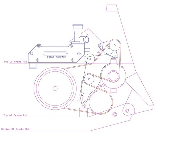
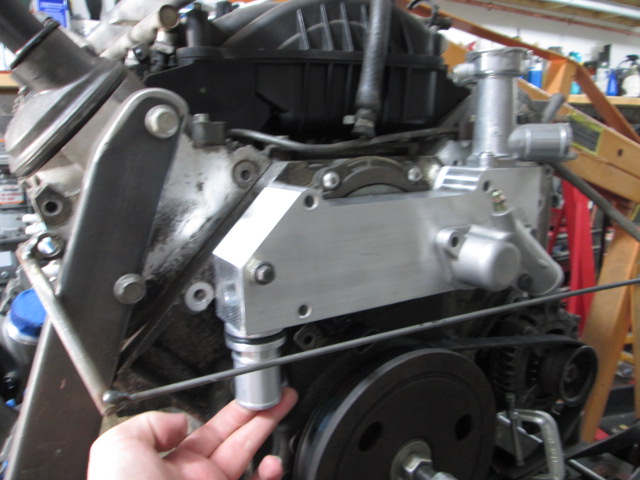
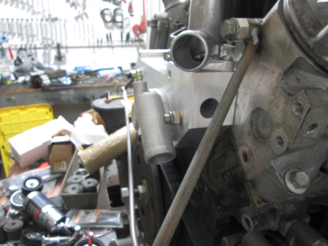
Here is the proposed layout for the electric water pump version:
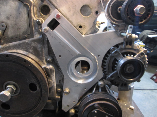
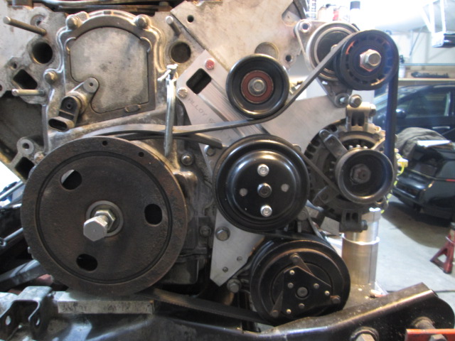
Here is the prototype back plate/accessory mount plate for the mechanical water pump version.
|
|
|
|
fieroguru
|
MAR 02, 06:34 PM
|
|
LS4/F40 Fiero hasn't moved in a month or so. Still waiting for some nicer weather.
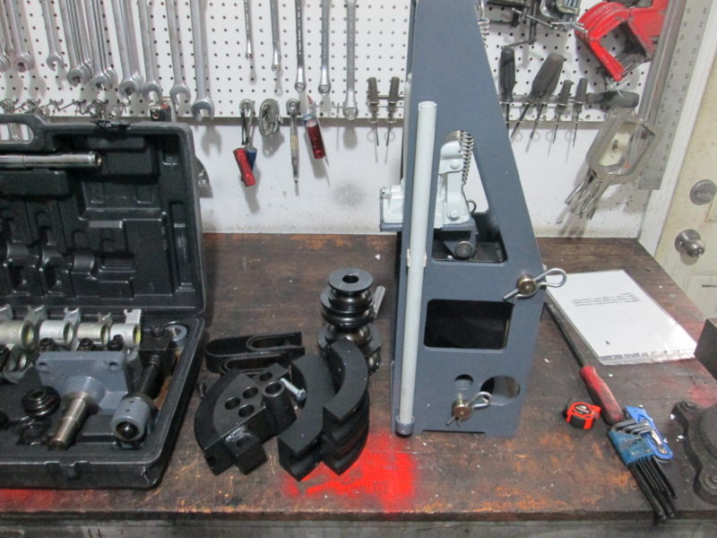
I have added a couple more tools to the collection, both are tubing benders.
Hand bender:
3/8",1/2",9/16",5/8",3/4",7/8” round tubing dies
1”,3/4" square tube dies
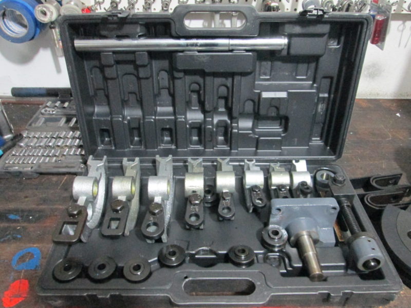
Hydraulic bender:
3/4", 1", 1-1/2", 1-5/8", 1-3/4 round tubing dies
|
|
|
|
Mike Morris
|
MAR 02, 08:38 PM
|
|
|
You do great work. Nice job ------------------
1999 Camaro Z28 B4C Heads Cam Intake Stall etc
1992 Ford Mustang LX 5.0 331 R block S trim Intercooled
1988 MR2 SC Cammed,Pulley etc
1988 Corvette Cammed stalled bolt ons
1985 Fiero SE V6-Transgo,stall,K&N,cat EGR delete,Ported TB
|
|
|
|
Will
|
MAR 04, 04:28 PM
|
|
| quote | Originally posted by fieroguru:
There are many reasons that lead to that placement, but the top 5 (not in any particular order):
- Current locations opens up potential front engine/RWD applications - probably a much larger market than LS swapped Fieros.
- I can use the same base housing for the electrical and mechanical versions (just install a plug for the mechanical versions).
- Keeps hose out of the way for installing the belt - especially if you need to do it away from the garage.
- Eliminates the hose from view... I am a little fussy about visible hose and wiring clutter.
- Didn't find a hose inlet neck that I liked that could be surface mounted, clear the frame rail, had proper placement for the inlet neck mounting bolts to clear the coolant passages, and with a seal surface that could clear the existing bolt hole locations in the water housing (I have 10 or 15 of the water inlets on the shelf trying to find something I was happy with.
Here is the proposed layout for the electric water pump version:
|
|
Not enough clearance to battery tray or frame rail to bring it out of the page and then install a 90 degree elbow?
|
|
|
|
fieroguru
|
MAR 04, 05:37 PM
|
|
| quote | Originally posted by Mike Morris:
You do great work. Nice job
|
|
Thanks! I just wish I had more free time to make quicker progress.
| quote | Originally posted by Will:
Not enough clearance to battery tray or frame rail to bring it out of the page and then install a 90 degree elbow? |
|
I have never verified clearance to the battery tray for any swap... I just assume it will be removed.
There are options for a 90 degree neck off the face, but it is very tight... It also puts the hose in the way of installing the belt 100% from the top, and ultimately I liked the "look" with the hose hidden.
|
|
|
|
fieroguru
|
APR 07, 06:49 PM
|
|
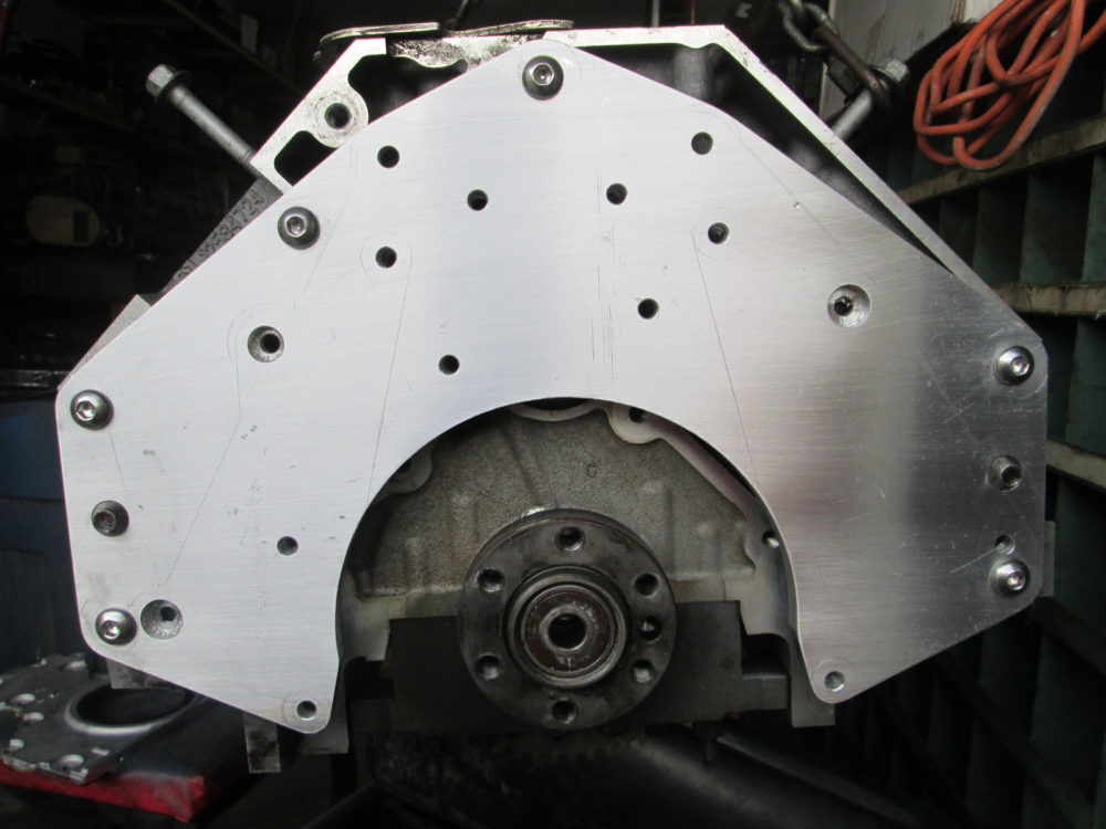
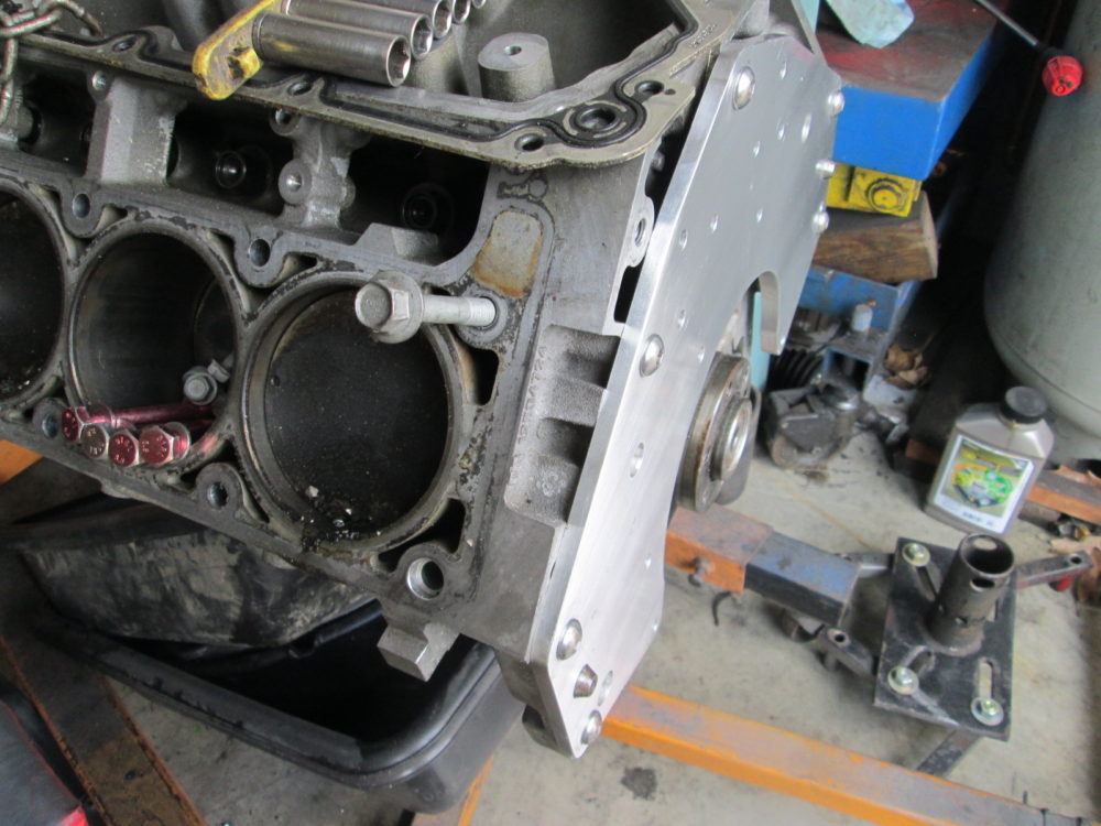
Made some chips fly over the weekend. The engine is a windowed LS3 from a friend.
I have long theorized that with the changes in crankshaft length and bellhousing patterns, a thin adapter plate would allow the LS4/F40 flywheel and starter setup to be used for "all" LS based engines. The minimal thickness does pose a few challenges, but I have solutions for those... not done yet, but good progress none the less.
A customer picked up a Europe F40 expecting it to have the 3.091 final drive. Instead, it had the 3.348 final drive, which matched the final drive in his current transmission. So we worked out a deal and I now have a 3.348 final drive and two spare sets of the 0.62 6th gears.
|
|
|
|
Will
|
APR 08, 10:41 AM
|
|
Interesting take. Since the LS4 block is longer and the crank flange thinner, there's room for a thin plate if using the normal crank and normal block.
The normal LS crank flange stands ~.280" proud of the bellhousing, so there's space for a little bit more than 1/4" of adapter plate. Yours looks closer to 3/8", but pics can be deceiving.
You've already figured out the transmission mount starter for some--but not all--applications, but an axial bolt starter, like from a Caddy Northstar, may fit next to a narrow oil pan and bolt into the adapter plate. That would require a remote mount filter.
|
|
|
|
fieroguru
|
APR 08, 07:51 PM
|
|
Yeah, I installed one of my LS4/F40 flywheels on a LS4 as well as a 2002 5.3 and the windowed LS3 and made the adapter plate to close the delta. It is slightly thicker than the .280 dimension. Still working on the internal geometry as the thinness of the adapter creates some complications and the LS engine family architecture has a couple as well. Right now I am balancing the solutions to the complications and their potential impact of manufacturing costs...
For now, the current starter mount works for several different transmissions, so I am keeping my focus on other areas for now.
More to come the next weekend I have some free time to work on it.
|
|
|
|
Will
|
APR 12, 07:43 AM
|
|
Nominally, the traditional small block crank flange is 11/16" proud of the bellhousing. The LS crank flange is 0.400 closer, so around 0.287. However, as you have previously noted, even on the FWD engines for which the crank flange is nominally flush, it can still stand 0.020 or so proud.
Would you have to incorporate the rear cover/RMS support into the adapter plate or just relieve the block side of the adapter plate to clear it?
|
|
|
|