
 
     |
| Blooze Own: An F355 Six Speed N* Build Thread (Page 89/126) |

|
Bloozberry
|
JAN 11, 10:22 PM
|
|
Thanks doublec4. You're doing some really interesting stuff too.
| quote | Originally posted by doublec4:
May I ask where you bought those spherical bearings? |
|
I bought them from Summit Racing, their part number FKB-FKS10.
| quote | Originally posted by Insky:
One of the main things that may prevent me from pursuing a project like this is liability. Has anyone done any in depth research about what kind of liability a builder may have if they eventually sell the project? |
|
I haven't done any such research, but then again I too believe my case is different from yours as you suggested. Once a provincially authorized professional engineer has completed and accepted the design and construction of my project, that certification is applicable in all three of the Maritime provinces in Canada, and likely would be acceptable to any other provincial jurisdiction across Canada as well. In that sense, I believe my liability would be limited provided that if I ever did sell the car, I were up front about the modifications, had a detailed account of the build process, and got any potential buyer to sign an affidavit acknowledging that he was aware of and accepted the modifications. I would also likely need to specify that the car was being sold "as-is, where-is" which also covers pretty well everything else. That will likely turn off many potential buyers and lower the overall value, but then again, I don't think that anybody going to this depth of modification ever expects to get his money back. If you do venture down this path it's probably best to keep and enjoy the car as long as you can, and expect that it will depreciate like any other car you would otherwise have bought.
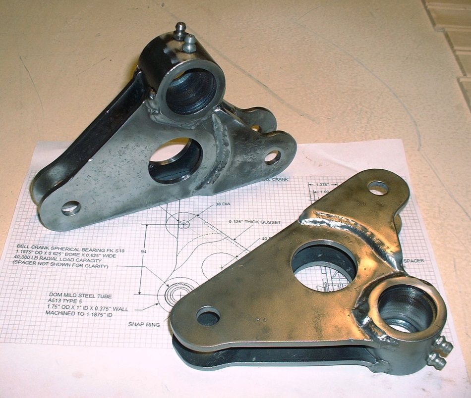
As for a little update, I've got a few more pictures to show off some progress. Today I finally managed to get some time on a friend's metal lathe to make the bell crank hubs. As planned, I started out with a piece of DOM 1.75OD X 1.0" ID structural steel tubing. It was $15 per foot so I bought 12" and cut two sections from it that were 1/4" longer than what I needed. Here's the sketch I used to make the hub, though I had to modify it slightly:
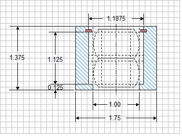
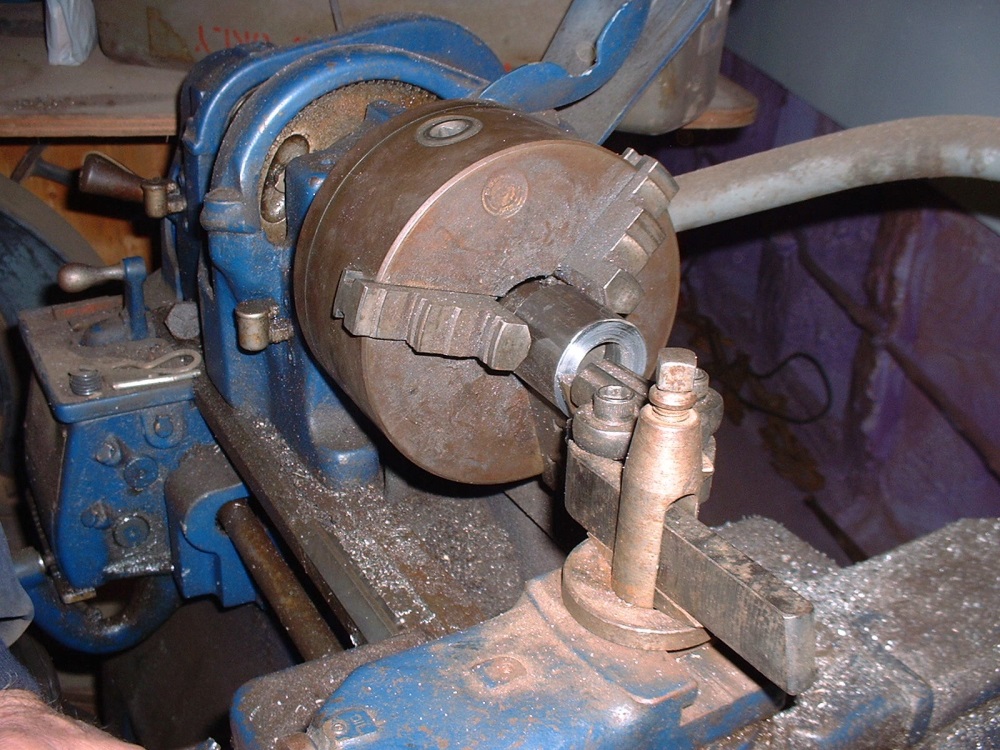
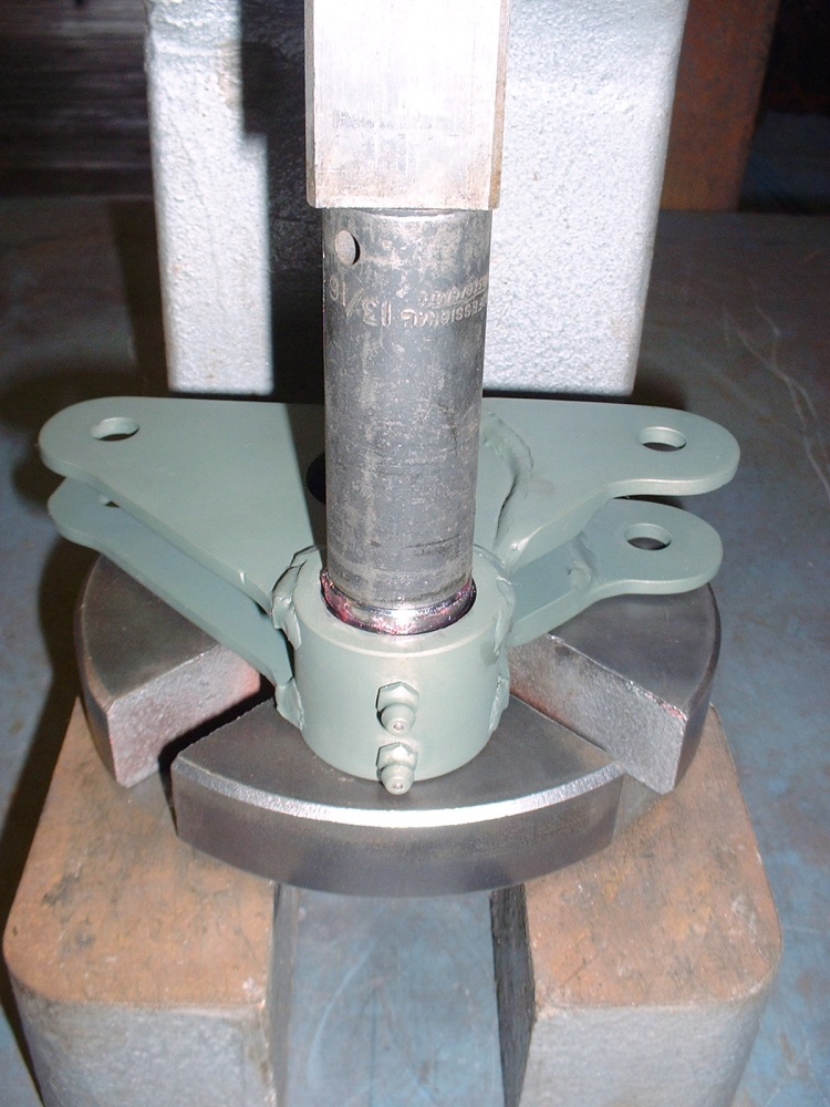
Once I had machined the inside diameter to 1.1875 (1-3/16") leaving a shoulder at one end, I machined a snap ring groove at the correct distance from the shoulder. The only snap rings I could get locally came in increments of 1/8" diameter so needless to say I had to upsize the rings from 1-3/16" in the drawing to 1-1/4". That meant I needed to increase the diameter of the snap ring groove, and the top lip just above the snap ring so that the larger ring would fit down the bore and into the groove. Here's a quick shot showing me squaring one end of a hub after roughly cutting it to length with a cut-off saw.
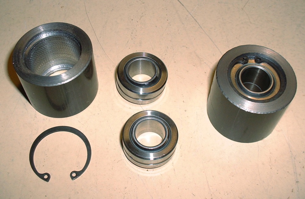
Things went pretty smoothly and although I was aiming for an interference fit between the bearing and the hub, the lathe (or perhaps the operator!) wasn't accurate enough to achieve any better than a finger-tight fit on both hubs. That's OK though since Locktite makes a special type of locking compound for just this sort of scenario. I have a bottle of it in the shop but can't remember the number off hand (604 maybe?). The F-18's use the same compound in their F404 engines to lock some of the axial bearings to their housings so I'm pretty sure it'll do the trick here.  Once the inside diameter machining was completed, I shaved off the extra 1/4" I had left on the length, centering the bearings between both ends. Here are the pieces that go into making one bearing hub together with one that's assembled: Once the inside diameter machining was completed, I shaved off the extra 1/4" I had left on the length, centering the bearings between both ends. Here are the pieces that go into making one bearing hub together with one that's assembled:
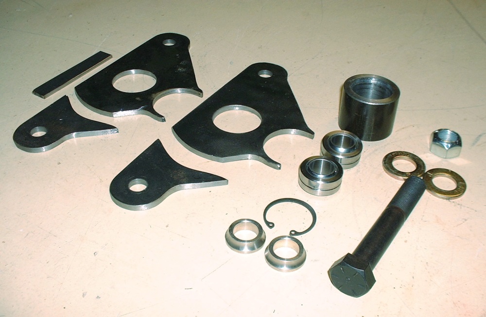
Since the last time I posted I spent some time drilling lightening holes in the bell crank arms, and fine tuning the fit of various pieces, so here's an updated photo of all the parts that go into a single bell crank:
To make sure the end pieces get welded to the main part of each arm at exactly the same location, I made up a simple jig that locates and pinches all the parts together just right.
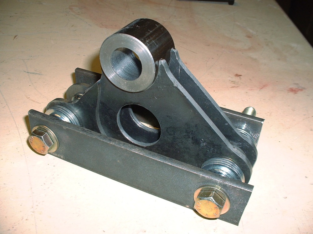
All of the washers and spacers and both pinching plates are simply there to keep everything properly oriented and to minimize warpage during welding. I'll get around to that tomorrow and post a few photos of the completed bell cranks then.
|
|
|
|
wftb
|
JAN 11, 10:31 PM
|
|
|
.this thread is not about liability .it is all about the incredible design and fabrication skills of the one and only Blooze . [This message has been edited by wftb (edited 01-15-2014).]
|
|
|
|
Sage
|
JAN 13, 07:47 PM
|
|
| quote | Originally posted by Bloozberry:
"While I am waiting for an opportunity to use a friend's lathe for the bell crank bearing housings, I thought I'd get around to something I've been meaning to do for a while: create an index for the thread. For convenience, I've edited my very first post on page 1 with a guide to navigating the past 22 pages.
I should get around to some real progress by tomorrow. " |
|
An organized mind is one thing I truly appreciate!
As always, very nicely done, makes it super easy to navigate through the thread and look up specific topics without the need to scan every page. Thanks for taking the time.
The bellcranks look awesome, can hardly wait to see them finished and in place.
Thanks for letting us all watch.
HAGO!
|
|
|
|
Bozzie
|
JAN 14, 09:39 AM
|
|
|
|
|
Bloozberry
|
JAN 15, 09:27 AM
|
|
Thanks wftb, Sage, and Bozzie!  It's always nice to get some feedback. It's always nice to get some feedback.
Well, I've been meaning to post updated shots of the completed bell cranks for the past couple days now but it seems that PIP has something different in mind. I tried uploading photos again this morning and got lucky with one, but the rest simply get timed-out before they can load. It's been an on-going problem for three or four days and I know Cliff is working on a solution. So for now, here's a teaser until this gets sorted out:
|
|
|
|
Sage
|
JAN 15, 10:48 AM
|
|
Oh yea!
HAGO!
|
|
|
|
355Fiero
|
JAN 15, 12:15 PM
|
|
Looking great Blooz;
I look forward to seeing these mounted and the shock setup in the frame.
Keep posting the updates as we are all watching in amazement.
Cheers
Don
|
|
|
|
Bloozberry
|
JAN 15, 08:10 PM
|
|
Yay! PIP is up and running again! First order of business is to thank Sage and Don for their kind comments... I get energized by the feedback.
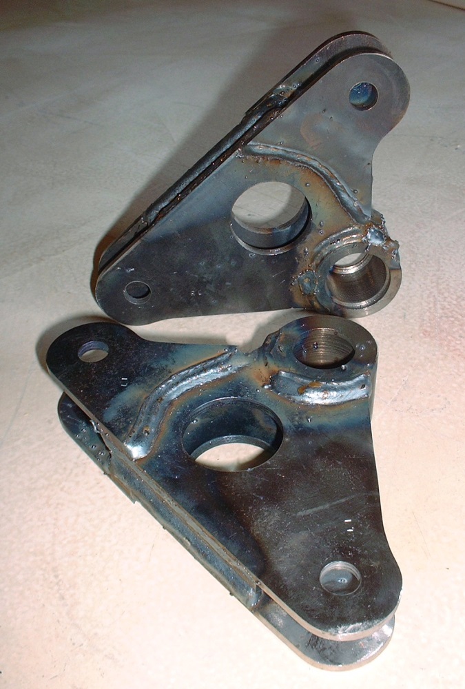
Second order of business is to finish posting the photos of the bell crank build up. Here's a close up of one of them showing just how hot things got to assure good weld penetration between the 3/16" plate steel and the hub which measures 9/32" thick. I find the heat patterns left on the steel are a good clue that there was even penetration. The other thing you can imagine is how disappointed I was with all the spatter, especially after making all the parts so clean and tidy!
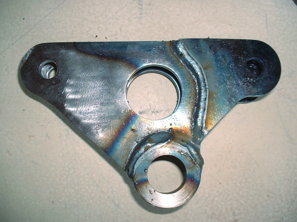
After chiselling off the little blobs of molten steel everywhere, attacking the cranks with a sanding disk on my angle grinder, and finally giving them a quick wire-wheeling I managed to regain some of the aesthetics lost to the welding process. At this point I decided to locate where the grease grooves on the bearings would line up with the hubs so that I could drill and tap the hubs for zerk fittings. It would have been a simple process except that I naively believed that I could coax a dull and chipped 1/4" x 28 tap into making threads in four little holes. (You can probably see where this is going.) The first two holes were painful with the tap clicking rather than smoothly inching its way down into the holes I had just drilled. I thought to myself "What the heck... two down, two to go". About halfway through the third hole, the clicking sound abruptly ended in a "SNAP". Followed by a strange sound that sounded like "Mother-@$^*&$% SH_T!". The tap broke off even with the outside diameter of the hub, but was sticking in about 3/16" on the inside bore where the bearings need to go. It wasn't looking good and I had visions of having to remake an entire bell crank.  With unbelievable luck, I was able to break up the remnants of the tap using a hammer and pin punch and got it out. I was even able to salvage the threaded hole with a (brand) new tap and make the zerk fit nice and tight. Whew! With unbelievable luck, I was able to break up the remnants of the tap using a hammer and pin punch and got it out. I was even able to salvage the threaded hole with a (brand) new tap and make the zerk fit nice and tight. Whew!
With that out of the way, the next step was to give the bell cranks a quick coat of self-etching primer and press the bearings into the hubs. I had to use an arbour press to get the bearings in the bores despite them being only finger tight earlier. I suspect the hubs deformed slightly due to the asymmetric weld, but it worked out in my favour. I didn't end up using any Locktite 680 to bond them to the hubs.
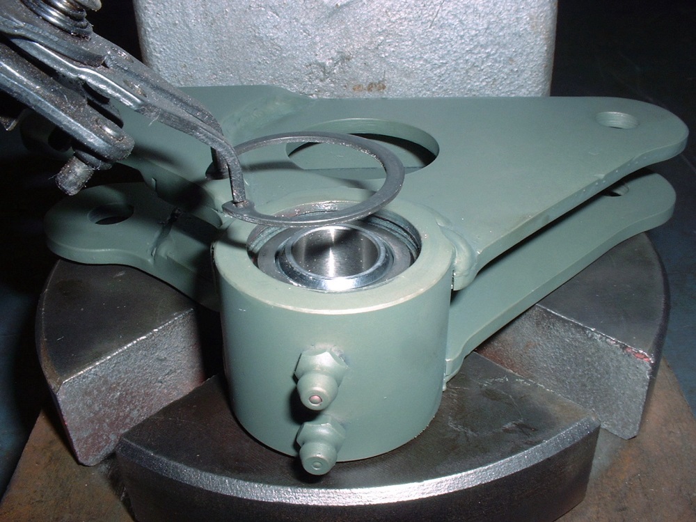
The last step was simply installing the snap rings to positively retain the bearings in the hubs:
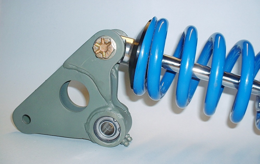
I installed the bell cranks to the QA1 coil-overs just to take a few pics and to get an idea how this was going to look. I think it was worth the effort so far.
|
|
|
|
X-Body
|
JAN 15, 11:57 PM
|
|
This may sound like a silly question, but why is the triangle made of two pieces?
As always, awesome thread, I check for updates daily (at least, lol).
|
|
|
|
Bloozberry
|
JAN 16, 07:15 AM
|
|
|
Thanks X-Body. I mentioned it earlier, but the reason each side of the main body of the bell crank was made in two pieces is so that I could accommodate the 5/8" width of the pushrod spherical bearing at one end, and the 1" wide spherical bearing at the end of the shock absorber. I could have made the bell crank 1" wide over it's entire length and used spacers on the pushrod bearings to make up the difference, but that would have forced me to use a wider hub since the triangular plates would have been moved further outboard and I would have otherwise lost the shoulder that I used to weld the plates onto the hub. So what's the big deal about using a wider hub? Not much, but I felt the bell crank was going to look quite large as it was and I wanted to minimize it's visual impact. A wider hub would have also forced me to change my bell crank mount design slightly to accommodate it.
|
|
|
|